
Quick-Start Guide
To view manuals, FAQs, videos, drivers, downloads, technical drawings, and more, visit www.startech.com/support.
Manual Revision: April 20, 2021 3:03 PM
To view manuals, FAQs, videos, drivers, downloads, technical drawings, and more, visit www.startech.com/support.
Product Diagram (SM2E1BMU31C)
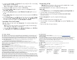
Exterior - Enclosure
Component
Function
1
Drive-Tray Screws x 2
• Used to secure the
Drive Tray
in the
Enclosure
.
2
Power & Activity LED
• Indicates that the
Enclosure
is receiving
power.
• Blinks during read/write activity.
3
USB-C Port
• Used to connect the
Enclosure
to the
Host
Computer
.
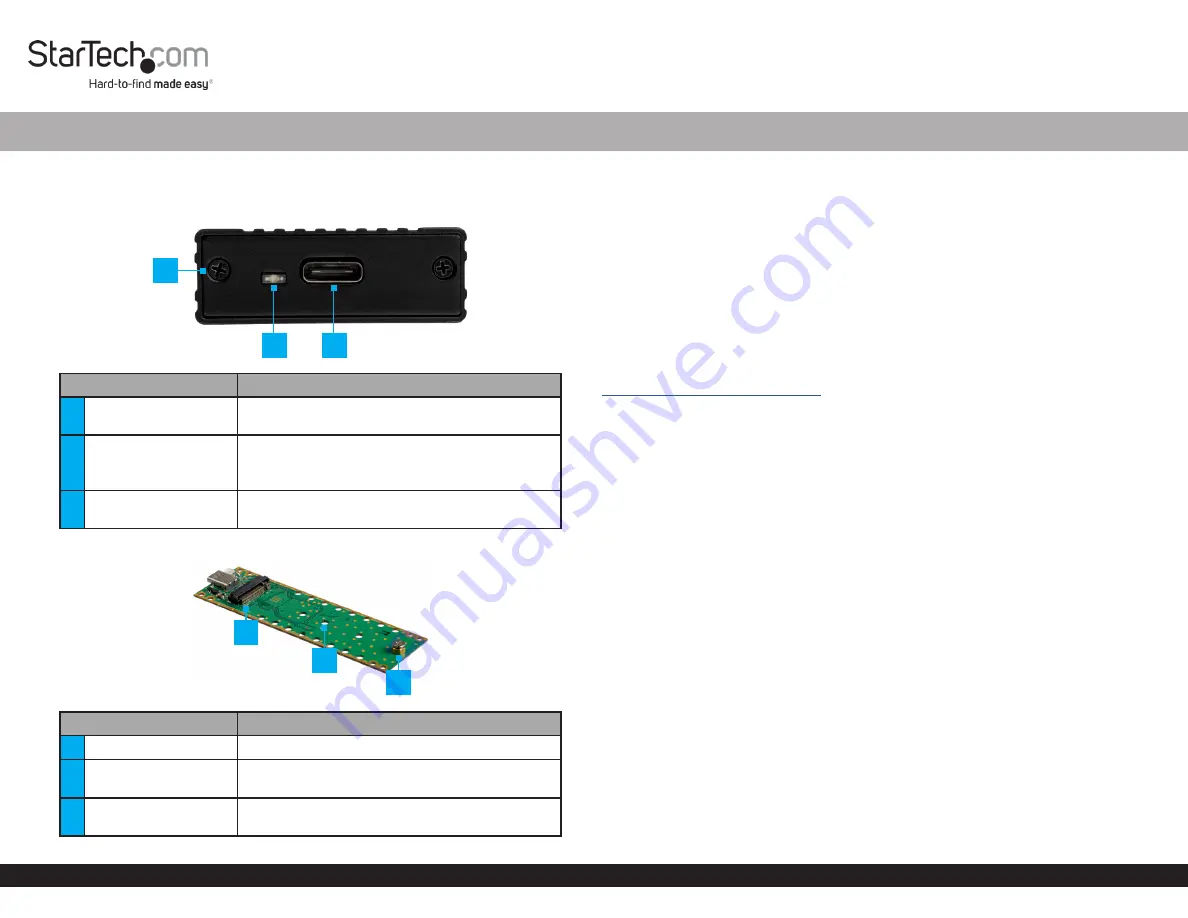
Interior - Drive Tray
Component
Function
4
Drive Connector
• Used to connect the
Drive
to the
Enclosure
.
5
Adjustable Drive
Length Holes
• Used to accommodate different drive lengths.
6
Drive-Mount Screw/
Standoff/Nut
• Used to secure the
Drive
to the
Enclosure
.
M.2 SATA/NVMe SSD Enclosure - USB 3.2 (10Gbps) w/ USB-C and USB-A Cables
Package Contents
• M.2 SSD Enclosure x 1
• USB-C to USB-C Cable x 1
• USB-A to USB-C Cable x 1
• Drive Installation Screw Kit x 1
• Micro Screwdriver x 1
• Quick-Start Guide
Product Information
For the latest requirements, please visit
Product Requirements
• M2 SATA/NVMe SSD x 1
• 30 mm, 42 mm, or 60 mm Drive Length
• Needle-nose Pliers x 2
Installation
Installing a Drive
Warning!
Handle drives with care.
1. Remove the
Drive Tray Screws
(x 2) from the
Enclosure
, using a
Phillips Head
Screwdriver
, and remove the
Cover Plate
.
2. Carefully pull the
Drive Tray
out of the
Enclosure
.
3. Remove the
Drive-Mount Screw
, using a
Phillips Head Screwdriver
.
4. Place the
Drive
next to the
Drive Tray
and align the screw holes in the
Drive
with
the
Adjustable Drive Length Holes
on the
Drive Tray
to determine the desired
Adjustable Drive Length Hole
setting.
Note:
If the drive mounting hardware is already installed in the correct position,
proceed to step 8.
5. Remove the
Drive Standoff
and
Nut
, using two sets of
Needle-nose
Pliers.
6. Insert the
Drive
Standoff
and
Nut
into the
Adjustable Drive Length Hole
(60, 42,
or 30) according to the length of the
Drive
.
7. Tighten the
Standoff
and
Nut
, using two sets of
Needle-nose
Pliers.
1
2
3
4
6
5


