background image

_____________________________________________________________________________________ 


Manual 


Transistor Servo Drive 


TV 6.2 


for DC Motors


TV

 6

.2


Version 
0506 


Stegmaier-Haupt GmbH
Industrieelektronik-Servoantriebstechnik

Untere Röte 5
D-69231 Rauenberg

Tel.:

06222-61021

Fax:     06222-64988

Email: info@stegmaier-haupt.de
Http: // www.stegmaier-haupt.de

Stegmaier-Haupt GmbH Industrieelektronik

____________________________________________________________________________________________


Summary of Contents for TV 6.2

Page 1: ... TV 6 2 Version 0506 Stegmaier Haupt GmbH Industrieelektronik Servoantriebstechnik Untere Röte 5 D 69231 Rauenberg Tel 06222 61021 Fax 06222 64988 Email info stegmaier haupt de Http www stegmaier haupt de Stegmaier Haupt GmbH Industrieelektronik ____________________________________________________________________________________________ ...

Page 2: ... Dimension 16 4 Adjustments Connection compact device 17 Connection multiple axes combination 17 Power connection 18 Ballast circuit 19 Output stage 19 Power section watchdog 20 Enable 21 Command value 22 Command value current 23 Current limiting 24 Actual value 25 Signals BTB outputs tacho fault overload over temperature stationary 26 Adjustments 27 P component 28 I component 28 Tacho control 29 ...

Page 3: ... EN60204 EN50178 EN60439 1 EN60146 EN61800 3 IEC UL IEC364 IEC 664 UL508C UL840 VDE regulations VDE100 VDE110 VDE160 TÜV regulations Regulations of Professional and Occupational bodies VGB4 The user must ensure that in the event of device failure incorrect operation loss of regulation or control the axis will be safely de activated It must also be ensured that the machine or equipment be fitted wi...

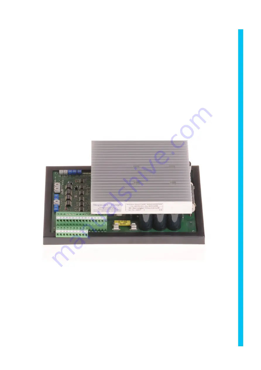
Page 4: ... strip The control electronics and the power section are galvanically connected The power semi conductors are comfortably over dimensioned Only components customary in trade and industrially standardised are used The most important operating modes are indicated by LEDs The PI adjustment and the rough tacho adjustment of the speed controller are achieved by 16 position binary switches Further adjus...

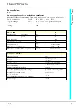
Page 5: ...er W 1440 Integrated quick fuses A 16 Armature choke type DR42 0 5 mH Dimensions plug in device wxh 16TE 6HE Dimensions switch cabinet plug in device wxhxd 170x240x80 mm Common specification Protection rating IP 00 Format VDE 0100 group C VDE 0160 Humidity rating class F acc to DIN 40040 Site of installation 1000m above sea level Operating temperature range 0 to 45 C Extended operating temperature...

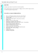
Page 6: ...t short circuits and circuits to earth Output stages Error tolerant switching off in case of over currents Ballast circuit Braking in case of a mains failure Wide band chopper power supply unit Differential amplifier 2 command value inputs 1 adjustable Slope limiting adjustable integrator Speed controller RVU with PI switching Current command value output Static and dynamic current limiting Speed ...

Page 7: ...IxR compensation Pot P2 IxR switch S1 K4 Integrator Switch S3 K1 Pot P1 INT 2nd command value adjustment Pot P9 Amplification P component Pot P3 X P binary switch S4 Amplification I component binary switch S5 Actual value differentiation switch S3 4 Commutation limiting resistor R111 R112 R190 DZ2 Zero adjustment Pot P8 Offset Continuous current Pot P7 I D Internal current limiting Pot P5 Imax1 Po...

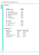
Page 8: ...locked LED C B tacho fault LED B A over temperature LED A Power section LED 7x C 15V LED C D 15V only for TV6 LED D E ballast circuit LED E F error LED F G over voltage LED G Signal test points Function Terminal no Connector no Drive ready BTB X2 21 22 X1 22a X1 24a Tacho fault X2 19 X1 28a Overload X2 18 X1 30a Stationary X2 25 X1 16a Current I actual value X2 20 X1 26a Over temperature X2 26 X1 ...

Page 9: ... 6ac Motor connection X1 15 X1 4ac Motor connection X1 16 X1 2ac Command value additional input X2 17 X1 32a Overload signal X2 18 X1 30a Tacho fault signal X2 19 X1 28a Current I actual X2 20 X1 26a Drive ready BTB X2 21 X1 24a Drive ready BTB X2 22 X1 22a Device ground GND X2 23 X1 20a Device ground GND X2 24 X1 18a Signal stationary condition X2 25 X1 16a Over temperature X2 26 X1 14a Test poin...

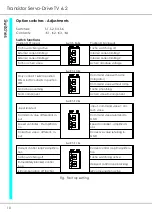
Page 10: ...value with ramp Integrator Command value without ramp No tacho smoothing Tacho smoothing No D component Actual value D component Switch S2 Kx input isolated input command value cor rect value Command value differential in put Command value referrend to GND Speed controller PI amplificati on Speed controller amplificati on 1 Corrective value different in put Corrective value referring to GND Switch...

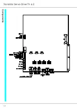
Page 11: ...ntrol electronics signals drive ready BTB enable current command value current command value stationary motor blocked tacho fault temperature Adjustment potentiometer ID continuous current XP amplification IxR compensation for armature voltage control nmax speed adjustment Offset zero point adjustment ...

Page 12: ...Transistor Servo Drive TV 6 2 12 ...

Page 13: ...TV6 2 13 3 Mechanical Installation ...

Page 14: ...Transistor Servo Drive TV 6 2 14 ...

Page 15: ...TV6 2 15 3 Mechanical Installation ...

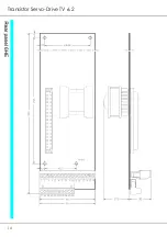
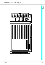
Page 16: ... 82 163 244 326 427 19 B 122 203 284 366 467 C 137 218 299 381 482 Mounting depth 270 mm For front mounting the lateral angle is at the front for wall mounting it is at the back Transistor Servo Drive TV 6 2 16 Axis module Axis module Axis module ...

Page 17: ...TV6 2 17 4 Adjustments Anschluss Kompaktgerät Anschluss Mehrachskombination ...

Page 18: ...ranges or different motor voltages separated win dings are advisable The power ratios of the transformer corresponds to the sum of all simultaneously applied continuous motor currents Please note that the relay contacts prece ding the transformer must be rated to its switch on current The transformer is to be protected with slow fuses The motor can be connected by means of an armature choke to the...

Page 19: ... circuitry has an over voltage watchdog In case of over voltage the device is internally blocked a short circuit is signalled and the ready contact BTB is opened In case of high ballast energy more powerful resistors can be installed in the fac tory special version pls indicate on order It is not possible to connect external ballast resistors ...

Page 20: ...s auxiliary voltage supply 15V 15V power section fuse failure buffer circuitry voltage too high permanent short circuit or circuit to earth over temperature optional rf to current limiting in case of over temperature In case of BTB faults or tacho faults the power section is immediately internally de activated The TV6 2 devices have a ballast circuitry and an integrated brake resistor The ballast ...

Page 21: ...d controller RVU will be enabled immediately When opening the contact or switching off the enable voltage the command value is immediately set to 0 and the speed controller drive is disabled after 2s emergency stop Output X1 32c X1 1 15V 6mA Input X1 30c X1 2 Input resistance 4kΩ Note Contact current 6mA Relays with gold contacts or Reed relays Input X1 18c X1 8 device ground GND Input X1 30c X1 2...

Page 22: ...tary command value input at terminal no 17 is not used it must be bridged to GND terminal no 23 24 Rf to page 23 Output X1 28c X1 3 10V 5mA Output X1 24c X1 5 10V 5mA Output X1 18c X1 8 device ground GND Input X1 26c X1 4 command value 0 to 10V The rotation direction is changed by means of the re lay contacts d1 and d2 Stationary condition when d1 and d2 are open Speed adjustments by means of the ...

Page 23: ...ns of the relay contacts d1 and d2 No correction if d1 and d2 are open Correction value adjustment by means of poti Pcorr Potentiometer resistance 5 to 10kΩ Command value voltage 0 to 10V Switch S2 K4 closed Input X1 32a X1 17 command value Input X1 18c X1 8 command value Voltage X1 26c X1 18c 0 to 10V Input resistance 100kΩ Differential input if the switch S2 K4 is open If the correction input is...

Page 24: ...rs a voltage of 10V is available across terminal X1 28c X1 3 against the GND X1 20c X1 7 Output X1 28c X1 3 10 Volt Input X1 16c X1 9 current limiting I1 0 to 10V Input X1 14c X1 10 current limiting I2 0 to 10V Output X1 20c X1 7 device ground GND Switches S6 K2 and S6 K3 closed ON The current limit I 1 is adjusted by means of the potentiometer P Icomm val 1 the current limit I 2 by means of the p...

Page 25: ...adjustment rf to page 29 For a 4Q control with a small control range up to 1 50 and a reduced de mand on the precision and dynamics the armature voltage can be used as actual value signal Input X1 20c X1 7 Tacho signal Input X1 22c X1 6 Tacho GND The tacho input X1 22c and the command value input X1 26c must have opposite polarities The tacho voltage is adjusted by means of the binary switch S9 rf...

Page 26: ...9 B Note Tachos with either a high voltage or a high inductance may cause the tacho watchdog to malfunction In order to overcome this problem insert a capaci tance of 0 1 F 400V at the tacho terminals and In case of overload or blocked drive the signal output X1 30a X2 18 switches from 15V to 0V after approx 2s The overload is signalled by means of the LED 19 C In case of a temperature increase to...

Page 27: ... used to adjust whether the additional input has reference to zero or is on the same potential as the differ ential amplifier S2 K2 closed ON input with reference to point zero S2 K2 open OFF differential input The amplification of the additional input can be varied from 0 to 100 by me ans of the internal potentiometer P9 The integration time of the slope limiting device is adjusted by means of th...

Page 28: ...9 180 148 123 107 90 82 73 67 64 59 55 52k If the potentiometer P3 Xp is at right full scale and with the switches S4 S5 are in position 0 the amplification VP 10 The amplification can be increased up to the factor 30 by turning the potentio meter P3 Xp clockwise Please note that the function of the potentiometer P3 is a 1 x function The integration time of the speed controller RVU depends on the ...

Page 29: ...tacho adjustment Position 0 1 2 3 4 5 6 7 8 9 to F Poti position nmax Tach voltage 155 52 41 14 7 14 12 9 12 5 6 9 6 8 k Armature voltage control In order to control the speed by means of the armature voltage as actual va lue the switch S6 K4 must be closed ON Switch S9 in position 0 The fine adjustment of the maximum speed at maximum command value is achieved by means of the potentiometer P4 n ma...

Page 30: ...ed at the connector X4 3 by means of an oscilloscope The reference command value at the connector X4 1 is transferred to channel 1 and the control output at X4 3 to channel 2 of the oscil loscope The reference voltage is activated and switched off between 1V and 0V Examples for adjusted control values ...

Page 31: ...ernal voltage across X1 16c X1 9 Imax1 and across X1 14c X1 10 Imax2 The external signal can be attenuated by means of the internal potentiometers P5 Imax1 and P6 Imax2 For the combination of speed torque control the torque is adjusted at the in puts X1 16c and X1 14c By means of the potentiometer P7 ID it is possible to adjust the continuous current for both torque directions between 2 and 100 of...

Page 32: ... the servo amplifier must be within the motor characteristic The limiting line for the amplifier is drawn at 2 x I rated which corresponds to 10V current com mand value Then the straight reduction line is drawn tangentially to the motor characteristic 1 Determine the max permissible current for maximum speed triggering point IN2 2 Determine the slope s of the current straight reduction line up to ...

Page 33: ...e voltage 0V command value additional input bridged to GND Adjust switch S9 to tacho voltage for armature voltage control adjust to 0 Switch S4 in position 2 switch S5 in position 2 Adjust potentiometer Imax to approx 10 Potentiometer Xp to 50 Potentiometer ID 100 Potentiometer IxR left full scale Potentiometer nmax left full scale Potentiometer INT left full scale Jumpers S6 S13 S14 and SW1 2 3 S...

Page 34: ...t the measuring point X4 6 by means of an oscilloscope 2 6 Amplification of the speed controller Adjust the P component to a low position 1 5 switch S4 Adjust the I component according to the centrifugal mass of the drive switch S5 big centrifugal mass high adjusted value small centrifugal mass low adjusted value At 10 of the speed increase the amplification by turning the potentiometer XP clockwi...

Page 35: ...e V Current command value Imax2 external voltage V Speed controller settings Switches Tacho adjustment S9 Position P component S4 Position I component S5 Position Potentiometers Speed nmax P4 Position Peak current Imax1 P5 Position Peak current Imax2 P6 Position Continuous current ID P7 Position Integrator INT P1 Position Amplification Xp P3 Position IxR Kompensation P2 Position Optional switch cl...

Page 36: ...mature voltage max V Armature current peak A Armature current continuous A Tacho voltage max V Acceleration V ms Integrator V ms Motor data Type plate specifications Manufacturer Type Serial No Motor voltage V Motor current A Tacho voltage V min 1 Tacho type Brake V Fan V ...

Page 37: ...bservance of the manual which is included in all consignments non observance of the electrical standards and regulations improper maintenance acts of nature All further claims on transformation diminution and replacement of any kind of damage especially damage which does not affect ou r device cannot be considered Follow on damage within the machine or system which may ari se due to malfunction or...

Page 38: ...Transistor Servo Drive TV6 2 38 ...

Page 39: ...TV6 2 39 8 Circuit Diagrams ...

Page 40: ...Transistor Servo Drive TV6 2 40 ...

Page 41: ...TV6 2 41 8 Circuit Diagrams ...

Page 42: ...Transistor Servo Drive TV6 2 42 Stegmaier Haupt GmbH Tel 06222 61021 Fax 06222 64988 Email info stegmaier haupt de ...

Reviews: