background image

stewmac.com 

©2018 StewMac 

page 1 of 14

Sheet #i-2203  Updated 5/18

Easy instructio

ns!

Clear pictures sho

w where

each part goes

.

C L A S S I C   P E D A L   K I T

Disaster

Transport

StewMac

Assembly

Instructions

The Disaster Transport is an analog 
voiced digital delay with 625ms 
delay time, all analog dry signal path, 
true bypass and added modulation. 
It was designed as an anti-modern 

delay for those who appreciate a nice tape echo with all its 
peculiarities. Its unique tone control doubles as a noise filter 
on longer delay settings and really helps the delay shine 
with a dirty signal. The mix control allows you to boost the 
effected signal to nearly 4x the original signal level and the 
modulation can go from subtle pitch shifting warble to ultra 
fast tremolo speeds while the LED visually shows the rate.

An EarthQuaker Devices original, the Disaster Transport 
has been out of production for some time, but now you 
can build your own! 

IN COLLABORATION WITH

R A R E  

/

  V I N TA G E  

/

  H A R D   T O   G E T

WHEN YOU CAN’T BUY IT 

BUILD IT

EarthQuaker

Devices

Kit case is unpainted

Summary of Contents for Disaster Transport

Page 1: ...ll its peculiarities Its unique tone control doubles as a noise filter on longer delay settings and really helps the delay shine with a dirty signal The mix control allows you to boost the effected signal to nearly 4x the original signal level and the modulation can go from subtle pitch shifting warble to ultra fast tremolo speeds while the LED visually shows the rate An EarthQuaker Devices origin...

Page 2: ... well on the kit case Spray paints like Rustoleum or Krylon are a durable finish You might want to paint the case before building the kit so you won t need to take the parts back out for painting A way to add custom graphics is to print them from your computer onto waterslide decal paper If you use decals protect them from scratches by spraying clear topcoats over them Tools and supplies Required ...

Page 3: ...pacitor 1 7336 474J 100V 474J 100V 1MΩ resistor 1 7367 47KΩ resistors 3 7369 10KΩ resistors 11 7362 100Ω resistors 2 7352 2K2Ω resistor 1 7376 22KΩ resistors 4 7379 220KΩ resistors 3 7381 470KΩ resistors 4 7382 100KΩ resistor 1 7365 15KΩ resistor 1 7378 150KΩ resistor 1 7373 103J 100V 103J 100V 2 1mm DC power connector 1 7468 3PDT latching footswitches 2 1611 Metal case with 4 screws 1 7600 Circui...

Page 4: ...k Black Red Brown Red Red Black Red Brown 22KΩ resistors 4 7379 220KΩ resistors 3 7381 Red Red Black Orange Brown 100KΩ resistor 1 7365 Brown Black Black Orange Brown 47KΩ resistors 3 7369 Yellow Purple Black Red Brown Brown Green Black Red Brown 15KΩ resistor 1 7378 100Ω resistors 2 7352 Brown Black Black Black Brown EarthQuaker Devices Disaster Transport Rev2 2010 EarthQuaker Devices Disaster Tr...

Page 5: ...hows this stripe Install each diode so that its stripe matches the direction shown on the circuit board EarthQuaker Devices Disaster Transport Rev2 2010 10K 1M 10 1 1 IJ B5K B50K B100K C500K B5K B25K I O G OJ L L G M F 22 100K 47K 470K 470K 470K 47 470K 47K 47K 10K 10K 100u 100u 100u 100u 100u 100u 10K 10K 10K 10K 10K 10K 100 100 10K 15K 150K 10K 220K 220K 2K2 22K 22K 22K 22K 022 022 022 022 1 1 1...

Page 6: ... Devices Disaster Transport Rev2 2010 10K 1M 10 1 1 IJ B5K B50K B100K C500K B5K B25K I O G OJ L L G M F 22 100K 47K 470K 470K 470K 47 470K 47K 47K 10K 10K 100u 100u 100u 100u 100u 100u 10K 10K 10K 10K 10K 10K 100 100 10K 15K 150K 10K 220K 220K 2K2 22K 22K 22K 22K 022 022 022 022 1 1 1 1 1 01 001 1 1 1 001 022 0022 022 220K OJ OG G IG I V 10K 1M 10 1 1 IJ B5K B50K B100K C500K B5K B25K I O G OJ L L ...

Page 7: ...t has a flat side On the circuit board its location outline also has a flat side install the transistor to match this outline EarthQuaker Devices Disaster Transport Rev2 2010 10K 1M 10 1 1 IJ B5K B50K B100K C500K B5K B25K I O G OJ L L G M F 22 100K 47K 470K 470K 470K 47 470K 47K 47K 10K 10K 100u 100u 100u 100u 100u 100u 10K 10K 10K 10K 10K 10K 100 100 10K 15K 150K 10K 220K 220K 2K2 22K 22K 22K 22K...

Page 8: ... 4 off of the other This allows it to jump lugs on the footswitch Solder the leads onto the board The longer lead goes into the through hole marked OJ EarthQuaker Devices Disaster Transport Rev2 2010 10K 1M 10 1 1 IJ B5K B50K B100K C500K B5K B25K I O G OJ L L G M F 22 100K 47K 470K 470K 470K 47 470K 47K 47K 10K 10K 100u 100u 100u 100u 100u 100u 10K 10K 10K 10K 10K 10K 100 100 10K 15K 150K 10K 220K...

Page 9: ...work well for removing the pins Usetheadhesivefoamtapetoinsulatethebackofthethree pots that lay over the circuit board from the soldered leads of the other parts Solder the pot in place making sure the foam back sits at the back of the board Pots should be installed with their leads facing to the left B100KΩ depth pot 1 7453 Apply adhesive foam tape to back of this pot C105 rate pot 1 7464 Solder ...

Page 10: ... is shorter than the positive Install the mounting bezels through the front of the enclosure Fromtheinside slipalockwasherandnutonboth andtightenthemupusinga3 8 socket InserttheLEDsinto the bezel so the flat side short lead faces the holes for the footswitches Feed the leads through the plastic plug press the plug down until it s tight in the bezel The LEDs will be held in place when you solder th...

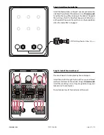
Page 11: ...e by the control pots Install their shafts through the top of the case and thread washers onto them on the outside Using a 10mm wrench install the mounting nuts so they are good and snug but take care not to overtighten Do not connect any of the lead wires at this point EarthQuaker Devices Disaster Transport Rev2 2010 10K 1M 10 1 1 IJ B5K B50K B100K C500K B5K B25K I O G OJ L L G M F 22 100K 47K 47...

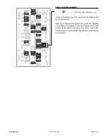
Page 12: ...G M F 22 100K 47K 470K 470K 470K 47 470K 47K 47K 10K 10K 100u 100u 100u 100u 100u 100u 10K 10K 10K 10K 10K 10K 100 100 10K 15K 150K 10K 220K 220K 2K2 22K 22K 22K 22K 022 022 022 022 1 1 1 1 1 01 001 1 1 1 001 022 0022 022 220K OJ OG G IG I V 1 4 mono jacks 1 4 2 4652 Positive lug facing upward EarthQuaker Devices Disaster Transport Rev2 2010 10K 1M 10 1 1 IJ B5K B50K B100K C500K B5K B25K I O G OJ ...

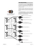
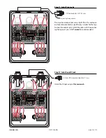
Page 13: ...ng to the bypass switch solder the lead labeled IJ to lug 2 Solder the I lead to lug 1 Solder the O lead to lug 4 Solder the G lead to lug 7 Solder the OJ lead to lug 5 jumping to lug 3 Continuing to work to the right solder the L lead to the positive long lead of the bypass LED Solder the negative short lead to lug 8 on the switch Moving on to the modulate switch solder the L to the positive long...

Page 14: ...ully counterclockwise subtle repeats around 9 o clock strong naturally decaying repeats at noon near infinite repeats around 2 o clock and full on self oscillation fully clockwise Depth Sets the depth of the modulation to the delay line The modulation is true pitch shifting vibrato higher depth settings will give sea sick pitch bending lower settings will yield a more natural chorus leslie tremolo...

Reviews: