background image


Original Instructions, Revision 1 August 2020


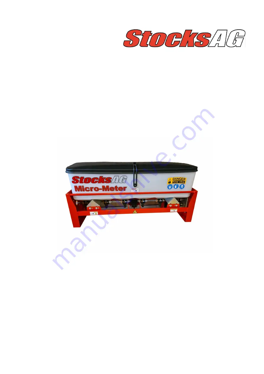
MICRO METER 


i

-

CON


Original  Operating  Manual  and parts list    


Read carefully before installation and 

operation 


This document must not be copied duplicated or distributed without prior consent .                      

All and patent rights apply  


STOCKS AG LIMITED, CROMWELL ROAD, WISBECH, CAMBRIDGESHIRE, UK. 


Tel: 00 44 (0) 1945 464 909  Email: sales@stocks

-

ag.co.uk  www.stocks

-

ag.co.uk


Summary of Contents for MICRO METER

Page 1: ...rtslist Read carefully before installation and operation This document must not be copied duplicated or distributed without prior consent All and patent rights apply STOCKS AG LIMITED CROMWELL ROAD WISBECH CAMBRIDGESHIRE UK Tel 00 44 0 1945 464 909 Email sales stocks ag co uk www stocks ag co uk ...

Page 2: ...ng a blockage 11 11 2 Storage 11 11 3 OPTIONAL Heavy Duty Waterproof Cover 11 11 4 Disposal 11 12 Machine Mounting 12 13 1 i CON Control System 13 13 2 Wiring diagram 13 13 3 Electrical Connections 13 14 Machine Components 14 15 1 i CON instrument functions 15 15 2 Precision farming software access OPTIONAL 15 16 1 Feed Shaft Speed 16 16 2 Feed Roller Adjustment 16 17 i CON Calibration page 1 17 1...

Page 3: ...ve feed rollers may be required The operator alone bears the associated risk if used for unintended use Intended use also includes compliance with the conditions for operation maintenance and repairs The implement may only be used maintained and repaired by persons who have relevant experience and aware of the risks involved The manufacturer is not liable for any resulting damage if the machine is...

Page 4: ...ingdom by Statutory Instrument 2008 No 1597 The Supply of Machinery Safety Regulations 2008 as amended The following standards have been applied in the design and construction of this machine BS EN ISO 12100 2010 Safety of machinery Basic concepts general principles for design Basic terminology methodology BS EN ISO 4254 1 2015 Agricultural machinery Safety General requirements BS EN ISO 4254 8 20...

Page 5: ...ngdom by Statutory Instrument 2008 No 1597 The Supply of Machinery Safety Regulations 2008 as amended The following standards have been applied in the design and construction of this machine BS EN ISO 12100 2010 Safety of machinery Basic concepts general principles for design Basic terminology methodology BS EN ISO 4254 1 2015 Agricultural machinery Safety General requirements BS EN ISO 4254 8 201...

Page 6: ...f damage is caused by external forces operator error modifications Jet washed or if the machine has not been used for its intended use Contact the company whom you purchased the machine from in the event of any problems or before at tempting any repair If the base machine or the controls system are modified in any way this will void any warranty claim Please see our conditions of sale for full det...

Page 7: ...not affected when the machine is in use If in doubt contact the vehicle manufacturer for more information After working the machine ensure that any unused product is returned safely to its original packaging Stocks AG Ltd does not accept any liability for the storage and use of the material being applied If unsure contact the material supplier for more information WARNING Always adhere to the warn...

Page 8: ...stem immediately by pressing and holding down the left hand rubber end cap on the instrument control panel for approx 2 seconds then release to power off 2 Disconnect the power supply by unplugging the power cable or removing the inline 40amp fuse POWER ON OFF ...

Page 9: ...ly 3 Ensure all feed outlets and all feed hoses are clear of any product Daily checks 1 Check the feed motor is working correctly 2 Ensure feed outlets and feed hoses are clear of product and spreading correctly After each use 1 Empty hopper and clean the machine thoroughly ensuring all product residue has been cleaned from the hopper feed rollers and housings 2 Store in dry conditions to protect ...

Page 10: ...ult in serious injury WARNING Do Not Jet Wash This machine is not designed to withstand Jet Washing WARNING Danger moving parts Risk of serious injury whilst the machine is in operation WARNING Risk of injury Keep a safe distance whilst the machine is in operation WARNING Keep Clear Maintain a safe distance from the machine when in operation Wear the appropriate protective personal equipment ...

Page 11: ...e hopper is empty after each and use and cleaned thoroughly before storage Store in dry conditions to protect the machine and control system from moisture Always clean and spray electrical connectors with a moisture repellent spray when not in use for long periods 11 3 Optional PVC Waterproof Covers Heavy duty White PVC covers fitted with eyelets and bungie cord for easy attachment available for a...

Page 12: ...blies can be fixed to the C section mounting rail to give the planned spacing by sliding each along the rail and locking into position using the integral bolts Two 1m lengths of rail supplied with each hopper unit to be cut down or extended to suit the implement width as required or fitted directly under the hopper units with the brackets supplied NOTE If the spreader cone assemblies are positione...

Page 13: ...per Level Sensor TJ251A Cut Out Switch TJ252 OPTIONAL Ground Speed Radar TJ233A OPTIONAL 6m Radar Cable TJ234 13 3 Electrical Connections Power requirement is 12 volts with a minimum continuous 30amp supply Ensure the power supply cable is connected direct to the vehicle battery to ensure maximum power Connect the positive wire fused to the positive terminal and negative earth connection to the ne...

Page 14: ...pposite mode by changing the position of the 2 wires inside the switch so that the switch is out of work when the sprung is at rest To change over remove the PVC cover plate held in position with the retaining screw to access the wiring terminals Remove the 2 wires from terminals 13 and 14 and re connect to terminals 21 and 22 nearest the gland nut then re fit the PVC cover plate NOTE the area met...

Page 15: ...e Nudge on the move rate adjustment in pre set increments user programmable NOTE a comprehensive control system user guide also supplied packed with the i Con instrument 15 2 Precision farming software access OPTIONAL The instrument can be unlocked to activate the precision farming program as a cost option This is something that can be requested when the machine is purchased or can be added at a l...

Page 16: ...mmended for any other application If changing feed rollers from Standard to Deep Groove please contact your local dealer for more information 16 2 Feed Roller Adjustment Standard feed roller with matching profile washer Deep Groove feed roller with matching profile washer Feed rollers slide in their housings to expose between 0 100 of the roller to the material in the hopper Adjustment is made by ...

Page 17: ...ieve your desired field speed displayed in the top right corner of the screen then re configure the feed roll assembly and repeat the calibration procedure 7 Prime the feed rollers with product by pressing and holding briefly the prime button on the junction box this will ensure a higher initial calibration accuracy empty the contents of the tray back into the hopper 8 For an Auto Calibration from...

Page 18: ...e required either Kilograms per Hectare or Seeds per Square Metre The standard default mode for the i CON is in Kgs Ha and you will have to reconfigure the display if you want to display Seeds per Square Metre You do not need to enter or change the TGW if working in Kgs Ha only if working in Seeds per Square Metre Refer to the RDS manual Section 3 page 21 Units and TGW Ensure you check the minimum...

Page 19: ... Unit is available The Combi Units are bolted to the rear of the existing hopper drive unit with the brackets provided The feed shaft is mechanically driven via a chain and sprocket drive Supplied with full spreader kit and 10m of hose Calibration of the Combi Unit must be carried out as an independent unit if applying a second product 19 3 Optional Nematicide Kit Safe handling of nematicides is e...

Page 20: ...20 20 Micro Meter i CON Partsdrawing 7 ...

Page 21: ...2 21 MM519 Feed Adjuster Fork 1 22 MM520 Feed Adjuster Wheel 1 23 MM521 M12x130 Threaded Rod 1 25 MM531 Drive Shaft Connector 85mm 2 per MM534 26 MM534 45cm Drive Shaft Extension 1 not shown Add On Unit only 30 MM047 Motor Mounting Bush 2 31 MM060A Motor Guard 1 32 MM318A Blanking Plate 1 3 per Add On Combi Unit 33 MM523 Pointer 1 34 MM228A Mounting Arm 2 35 FJ008A M6x6 Grub Screw 12 37 FJ103A 1 R...

Page 22: ...74 M10 024 M10 Nyloc Nut 4 Add On Unit only 75 n a Decal Serial No CE UKCA Mark 1 not shown 76 MD002 Decal Stocks AG 1 not shown 77 MD020 Decal Stocks MICRO METER 1 not shown 78 MD052 Warning Decal Kit 1 not shown 79 MD024 Decal Made in Britain 1 not shown 80 MD022 Decal i Con 1 not shown 81 FJ107F 7m Fused power Cable 1 not shown 82 TJ118C Instrument Connector Cable 1 not shown 83 TJ242A 6m Instr...

Reviews: