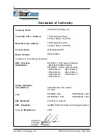
background image

StorCase

®

 Technology

Data Express

®

DE75i-A100

Removable

Ultra  ATA133

Low-Profile

Drive  Enclosure

User's Guide

Summary of Contents for DataExpress DE75i-A100

Page 1: ...StorCase Technology Data Express DE75i A100 Removable Ultra ATA133 Low Profile Drive Enclosure User sGuide...

Page 2: ...c StorCase Technology Data Express DE75i A100 Removable Ultra ATA133 Low Profile Drive Enclosure User s Guide PartNo D89 0000 0110D02 October2005 StorCase Technology Inc 17600 Newhope Street Fountain...

Page 3: ...escribed below All StorCase interface cables and other accessories specifically intended for use with the StorCase products identified above are also covered by this 7 year warranty Three Year Warrant...

Page 4: ...rior to servicing your system This warranty covers only repair or replacement of defective StorCase products as described above StorCase is not liable for and does not cover under warranty any costs a...

Page 5: ...1000 4 6 EN 61000 4 3 EN 61000 4 8 EN 61000 4 4 EN 61000 4 11 EN 61000 4 5 CAN CSA C22 2 No 950 95 UL 1950 EN 60950 1992 EN 60950 A2 1993 EN 60950 A1 1993 EN 60950 A3 1995 FCC Part 15 Class B AS NZS 3...

Page 6: ...eparation 6 Master Slave Drive Selection 6 Method 1 Recommended 6 Method 2 7 Configuring the Drive Carrier Circuit Board 7 Configuring the Receiving Frame Motherboard JP4 9 Installation 10 Installing...

Page 7: ...ng Holes 11 Figure 10 Unit ID Select Switch Location 13 Figure A 1 DE75i A100 Physical Dimensions 19 Figure B 1 Attaching the ON OFF Key 20 Figure C 1 Carrying Case 21 List of Tables Table 1 Unit ID S...

Page 8: ...435 0642 to arrange for a Return Material Authorization RMA A staff member will give you a Return Material Authorization RMA number to facilitate processing StorCase cannot accept returns which do not...

Page 9: ...hillips Machine Hd Screws AttachReceivingFrametoComputer 5 JumperPlugs 6 DriveLockKeys Figure 1 Package Contents 7 6 32 x 3 16 Phillips F H Screws Attach Drive and Cable Cover to Carrier 8 Alignment T...

Page 10: ...an Ultra ATA133 controller and hard drive s and appropriate 40 pin 80 conductor cable are required The StorCase Technology Data Express DE75i A100 is a removable low profile drive carrier and receivi...

Page 11: ...ckwise to the locked position The Unit ID Number Indicator displays the physical address of the DE75i A100 drive carrier when the carrier is Installed and Locked in the receiving frame or Removed from...

Page 12: ...ader Master Slave Setting JP6 ID0 ID1 ID0 Jumper installed on Pins 1 2 Factory Default for Master configuration ID1 Jumper installed on Pins 3 4 for Slave configuration Remote Drive Activity JP6 RLED...

Page 13: ...n the following sections for further information Master Slave Drive Selection Method 1 Recommended Using the factory installed jumper on your IDE drive In most cases the drive will be factory configur...

Page 14: ...the receiving frame both required for Method 2 Configuring the Drive Carrier Circuit Board The appropriate pins on the drive must be connected to JP3 on the carrier board These connections are require...

Page 15: ...Maxtor ATA100 Drive JP3 Pin 3 JP3 Pin 2 112a JP3 Pin 3 JP3 Pin 2 Western Digital ATA100 Drive Examples of Ultra ATA133 drive pin positions are shown in Figure 6 Remove and save all jumpers Install a...

Page 16: ...riate jumper setting must still be configured on JP6 ID0 ID1 located on the receiving frame motherboard Figure 4 For Master setting install jumper on ID0 Pins 1 2 For slave setting install jumper on I...

Page 17: ...rcuit board to the drive Figure 8 If you are installing only one drive carrier skip to Step 4 3 For Method 2 Users If a Master Slave cable was fabricated as outlined in the previous section install it...

Page 18: ...ption Pins JP6 ID0 ID1 located on the receiving frame motherboard Figure 4 4 With the drive carrier locked in place inside the receiving frame install the DE75i A100 into the 5 25 drive opening in the...

Page 19: ...er to Figure 4 for the receiving frame power connector location 9 Replace any expansion boards that may have been removed earlier Replace the system cover according to the manufacturer s instructions...

Page 20: ...o the drive 3 Use the alignment tool supplied with the DE75i A100 to select the unit ID number of the drive Refer to Figure 10 for the location of the Unit ID Select Switch inside the receiving frame...

Page 21: ...sts the Unit ID Select Switch settings and the valid AT IDE unit ID numbers Please note that all invalid switch settings have shaded boxes and result in a blank display in the receiving frame display...

Page 22: ...I O 12 Host Data 12 I O 13 Host Data 2 I O 14 Host Data 13 I O 15 Host Data 1 I O 16 Host Data 14 I O 17 Host Data 0 I O 18 Host Data 15 I O 19 Ground 20 Key NoPin 21 Reserved 22 Ground 23 HIOW O 24 G...

Page 23: ...16 Installation StorCase Technology Inc DE75i A100 User s Guide Rev D02 This Page Left Blank Intentionally...

Page 24: ...Appendix A Specifications Dimensions 17 DE75i A100 User s Guide Rev D02 StorCase Technology Inc APPENDICES...

Page 25: ...240m 304m to 15240m Shock 2 10g 60g 1 Non condensing with maximum gradient of 10 per hour 2 11 msec pulse width 1 2 sine wave Physical Specifications Carrier Receiving Frame Height 1 07 27 2mm 1 13 28...

Page 26: ...Appendix A Specifications Dimensions 19 DE75i A100 User s Guide Rev D02 StorCase Technology Inc Figure A 1 DE75i A100 Physical Dimensions Dimensions are for reference only...

Page 27: ...he rectangular shaped key lock mechanism access hole on the inside of the receiving frame Note that the pawl is in an upright position Insert the key into the key lock 2 Rotate the key 90 degrees coun...

Page 28: ...is designed to transport the DE75i A100 carrier from one location to another in a safe impact and moisture resistant environment Its compact dimensions 7 long x 9 wide x 3 5 high make it easy to carry...

Page 29: ...22 Appendix C Optional Accessories StorCase Technology Inc DE75i A100 User s Guide Rev D02 This Page Left Blank Intentionally...

Page 30: ...installation instructions Everyone at StorCase Technology is working toward the goal of providing you with the highest quality most cost effective products available on the market and we need your com...

Page 31: ...LINE AND STAPLE SHUT CUT ALONG THIS LINE FROM BOTTOM TO TOP OF PAGE BUSINESS REPLY MAIL POSTAGE WILL BE PAID BY ADDRESSEE NO POSTAGE NECESSARY IF MAILED IN THE UNITED STATES FIRST CLASS MAIL PERMIT NO...

Reviews: