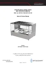
background image

PN 55009 

33” and 35” DEEP SERVICE REFRIGERATED DISPLAY CASES 

Rev A Date: 8.17.2009


I:\Oper Manual\Standard\Harmony_Service_Refrig_Oper_Manual_55009.pub 

PLEASE NOTE THE FOLLOWING:  


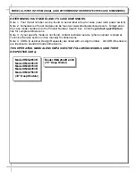
1.  YOUR SPECIFIC MODEL NUMBER IS ON THE SERIAL LABEL ON CASE REAR (NEAR MAIN POWER SWITCH).   
2. SEE 

“MODELS (AND THEIR RESPECTIVE CASE DIMENSIONS) LISTED IN THIS MANUAL” SECTION FOR          

ADDITIONAL INFORMATION REGARDING SPECIFIC CASE DIMENSIONS OF STANDARD MODELS AND CDRs. 

READ AND SAVE THESE INSTRUCTIONS 

Structural Concepts Corporation ·  888 E. Porter Road · Muskegon, MI  49441  Phone: 231.798.8888  Fax: 231.798.4960  ·  www.structuralconcepts.com 
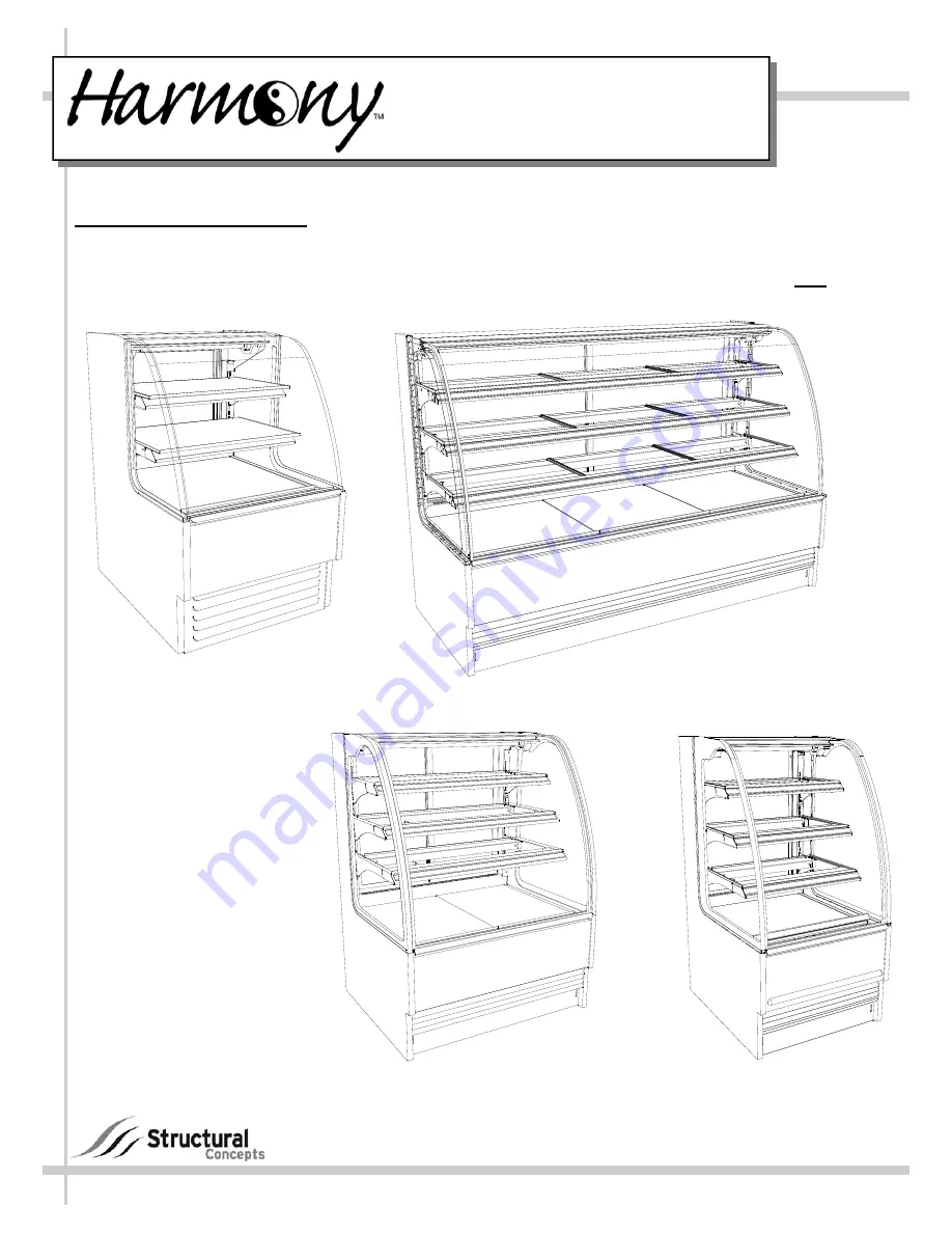
INSTALLATION &  

OPERATING MANUAL 

(HMG7553R)

(HMG3953R)

(HMG2653R)

(HMG2642R.4439) 

[35” Deep Model] 

HMG7553R 

[33” Deep Model] 

HMG3953R 

[33” Deep Model] 

HMG2653R 

[33” Deep Model] 

Summary of Contents for Harmony HMG2642R.4439

Page 1: ...AND THEIR RESPECTIVE CASE DIMENSIONS LISTED IN THIS MANUAL SECTION FOR ADDITIONAL INFORMATION REGARDING SPECIFIC CASE DIMENSIONS OF STANDARD MODELS AND CDRs READ AND SAVE THESE INSTRUCTIONS Structural...

Page 2: ...S ALIGNMENT ADJUSTMENT RAISING THE CURVED GLASS OPENING REAR DOOR REMOVING REAR DOORS DRAIN HOSE AND BRACKET PLACEMENT ILLUSTRATIONS MAINTENANCE FUNDAMENTALS STANDARD LIGHT FIXTURES MAINTENANCE REFRIG...

Page 3: ...www structuralconcepts com Simply enter the case model number into the Product Number Search box Click the product specification link for complete dimensions Note 3 If your specific model is not foun...

Page 4: ...ion Do not allow air conditioning electric fans open doors or windows to create air currents around display case as this may detrimentally affect proper case temperatures and operation WARNING Hazardo...

Page 5: ...ff from skid Maintain support of case at all times or center of gravity may cause case to fall Unlock Casters Roll unit to rear of skid Ramp Roll down ramp and off from skid Support while rolling case...

Page 6: ...placing product in case See illustration at mid right 5 Electrical Connections Remote Units Remove front or rear panel by removing screws and lifting off case Remote Unit Knockouts Glass Shelves Knock...

Page 7: ...Connect tub drain to floor drain Maintain 1 4 fall per foot to provide proper drainage Illustration at top right may not reflect every feature or option of your particular case 8 Evaporator Pan Drain...

Page 8: ...e plugged in or receptacles capped to turn on 12 Cases With Casters Lock and Unlock To lock casters press down on lever To unlock casters pull lever up See illustration at lower right 13 Cases With Le...

Page 9: ...check that temperature starts to drop If temperature controller does not begin cooling in a few minutes see temperature controller section in this operating manual for instructions Remote units witho...

Page 10: ...ain that front glass is properly aligned at both left hand and right hand side of case If not repeat the above procedure until front glass is properly aligned along both sides of case 18 Front Glass A...

Page 11: ...have swinging clear glass door View of Rear Doors being lifted up pivoted out and away from case View of Curved Glass being raised Main Power Switch Self Contained Only that opens with either left han...

Page 12: ...of Evaporator the Hose and Drain Trap MUST BE secured and positioned over Evaporator Pan to prevent water seepage spillage When sliding out Condenser Unit be careful that drain is not pulled from prop...

Page 13: ...lamp mounting sockets Remove bulb by applying even pressure from back side at the bulb ends and pulling the remaining contact from sockets See illustrations at mid and lower right Installation of lam...

Page 14: ...by rinsing thoroughly with water against the air flow direction Mild detergent removes smoke grease stains See illustration at top right Pull Out Refrigeration Package Remove the rear grille Grille ma...

Page 15: ...r Filter with Magnetic Strips on Rear Grille Remove air filter Rinse with hot water against air flow direction Use mild detergent to remove smoke and grease stains Monthly Condensing Coil Remove rear...

Page 16: ...on Heat Rod Evaporator System only Check that evaporator pan is plugged in Caution Evaporator pan may be malfunctioning Electrical Heat Rod Evaporator system If so water will overflow pan and seep ont...

Page 17: ...n shrouds Check that power is going to fans Check that fan wiring is connected on terminal blocks System Is Not Operating Check that the utility power is on Check the circuit breaker box for tripped c...

Page 18: ...s Settings for accuracy Check that ALL lights are plugged in and receptacles capped See MAINTENANCE FUNDAMENTALS LED LIGHT FIX TURES section in this manual for illustrations Case Lights Are Not Worki...

Page 19: ...ercharged Check that case is free of non condensables Check that the Liquid Line Drier Filter is not plugged Check Set Point temperature it may be adjusted too high Check System Operating temperatures...

Page 20: ...heat setting Check that the Thermostatic Element charge isn t depleted Check that the Coil is not iced up High Suction Pressure Check that Refrigerant Charge isn t too high Check that Compressor Valve...

Page 21: ...tacle box Quarterly Compressor Area Caution Be certain to disconnect power from case before cleaning Compressor Area Slide Roll compressor package out from under case Use moist cloth to wipe off dust...

Page 22: ...uralconcepts com SAMPLE ONLY SAMPLE ONLY SAMPLE ONLY 22 SERIAL LABEL LOCATION INFORMATION LISTED TECH INFO SERVICE Serial Label Location Information Listed Technical Information Service Serial labels...

Page 23: ...off before pressing the Prg key all modifications to parameters will be lost How To Activate Manual Defrost Press and hold the def key for at least 5 seconds How To Activate Deactivate Auxiliary Outp...

Page 24: ...alarms reset temp monitoring Summary Table of Alarm and Signals Display Buzzer and Relay Structural Concepts Corp 888 E Porter Rd Muskegon MI 49441 Ph 231 798 8888 Fax 231 798 0393 www structuralconc...

Page 25: ...tor min F 1 250 d6 Display on hold during defrost C 0 2 dd Dripping time after defrost min F 0 15 d 1 Display of defrost probe 1 C F F 5 Select Celcius C or Fahrenheit F flag C 0 1 Structural Concepts...

Page 26: ...as defined herein suffered or incurred by SCC as a result of or in connection with any act omission or use of the Goods by Purchaser its employees or customers or any breach of this Agreement by Purch...

Reviews: