1 OF 14
ISSUE
01
DATE
25 Jul 2018
SUBARU OF AMERICA
PART NUMBER
H001SFL400
PART NUMBER:
H001SFL400
DESCRIPTION:
LONG RANGE KEY START
REMOTE
ENGINE
START
SYSTEM
IMPREZA
/
CROSSTREK
INSTALLATION
INSTRUCTIONS
1
2
3
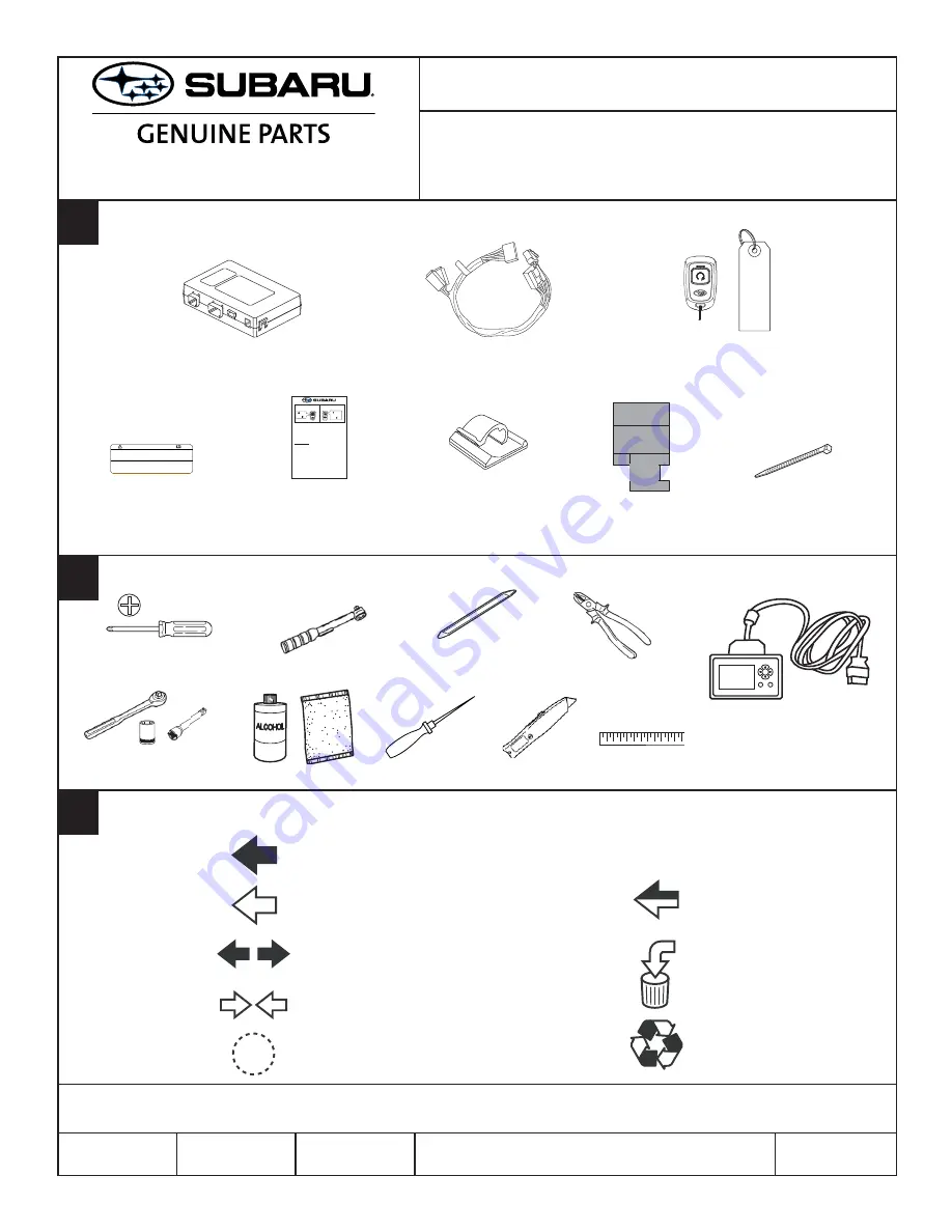
KIT CONTENTS
TOOLS REQUIRED
MEANING OF CHARACTERS
CAUTION: DO NOT SECURE ANY REMOTE START HARNESSES TO ANY YELLOW HARNESSES / CONNECTORS
(AIRBAG SYSTEM) IN THE VEHICLE.
SSM IV (DST-i)
Diagnostic Interface
Phillips Screwdriver
Short and Standard
Wire Cutters
Panel Removal Tool
:
Remove
: Tighten Torque
: Install
: Disconnect
: Connect
: Location of Clip or Screw
: Loosen
: Discard
: Re-use
B
A
Ratchet, 10mm Socket &
Extension
Remote Engine Start
Control Module (ECU)
Quantity=1
Remote Engine Start
Wire Harness
Quantity=1
Remote Engine Start
Transmitters w/ Warning Tags
Quantity=2
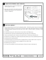
Under Hood
Warning Label
Quantity=1
Tie Wraps
20cm Quantity=4
39cm Quantity=8
REMOTE START QUICK REFERENCE*
Remote Start Activation
Press Two (2) Times
Within Three (3) Seconds
Remote Start Activation
Press Two (2) Times
Within (2) Seconds, Then
Press and Hold For Three (3)
Seconds
LONG RANGE ACTIVATION - ALL MODELS
ALTERNATE ACTIVATION -
PUSH BUTTON START MODELS
Remote Start Shutdown
Press and Hold For
Two (2) Seconds
Remote Start Shutdown
Press and Hold For
Three (3) Seconds
NOTE: All vehicle doors, hood, trunk or rear gate must be closed prior to activating the remote engine start
system. Any open entry point will prevent starting or cause the system to shut down.
Upon successful activation, the remote start fob will fl ash and beep one (1) time**, the horn will honk one (1) time
and the side marker lights, tail lights and parking lights will fl ash one (1) time. The system will check certain safety
preconditions before starting and if all conditions are met, the engine will start within fi ve (5) seconds. After the
engine starts, the remote start fob will fl ash and beep two (2) times**, the horn will honk one (1) time and the side
marker lights, tail lights and parking lights will fl ash one (1) time. While the engine is running via the remote engine
start system, the remote start fob will continue to fl ash one (1) time every three (3) seconds, the side marker lights,
tail lights and parking lights will remain illuminated and the power window switches will be disabled. The engine
will continue to run for fi fteen (15) minutes unless one of the safety parameters below is triggered. The system also
has a timer that will allow the system to operate for a maximum of twenty (20) minutes (under multiple remote start
activations). Using the factory ignition key (Turn start models) or Access key (Push button start models) to turn on the
ignition resets the twenty (20) minute timer.
If the engine turns over but does not start (or starts and stalls) the remote engine start system will power off and then
attempt to start the engine three (3) additional times. The system will not attempt to restart the engine if it determines
a vehicle malfunction is preventing it from starting. If the engine does not start after the three (3) additional attempts,
the remote engine start request will be aborted.
Remote Start Safety Parameters
For safety and security reasons, the system will fail to start or shut down the engine during remote start operation if
any of the following occur:
•
The remote start system has operated for twenty (20) minutes between ignition “ON” cycles
The horn will honk three (3) times and the parking lights will fl ash three (3) times
•
Any of the vehicle’s doors, trunk or rear gate are open
The horn will honk six (6) times and the parking lights will fl ash six (6) times
•
The vehicle’s hood is open
The horn will honk two (2) times and the parking lights will fl ash two (2) times
•
The ignition key is resting in the ignition cylinder (Turn start models)
The horn will honk two (2) times and the parking lights will fl ash two (2) times
•
The transmission shifter is not in the “park” position
The horn will honk two (2) times and the parking lights will fl ash two (2) times
•
The vehicle’s brake pedal is pressed before the vehicle ignition is turned “ON”
The horn will honk two (2) times and the parking lights will fl ash two (2) times
•
The vehicle’s engine idle speed has reached a level over 3,500 RPM (this will cause the vehicle to shut down)
•
The vehicle’s security system is triggered by opening the door, trunk or rear gate (if the security system is armed
at the time of remote start activation)
In addition to the items above, if the vehicle’s engine management system determines there is a safety risk due to a
vehicle related problem, the engine will shut down.
WARNING: TO AVOID DANGER OF CARBON MONOXIDE, NEVER REMOTE START A VEHICLE IN A CLOSED
SPACE SUCH AS A CLOSED GARAGE.
NOTE: Laws in some communities require that the vehicle be within view of anyone using the Remote Engine
Start. In some areas, use of the Remote Engine Start may violate state, provincial or local laws. Before using
the Remote Engine Start, check your state, provincial and local laws.
* See the vehicle owner’s manual for more details.
** Provided that the remote start fob is within the operating range of the system.
P/N: 4280648, Rev -
Quick
Reference Card
Quantity=1 English,
1 French
Torque Wrench
T
WARNING: / AVERTISSEMENT
This vehicle is equipped with a remote controlled engine starter.
To reduce the risk of serious Injury or death, switch engine starter
system into service mode and disconnect the vehicle battery
before performing any service on the vehicle.
Ce véhicule est doté d'un démarreur à distance. Pour réduire les
risques de blessures graves ou mortelles, mettre le démarreur à
distance en mode service et débrancher la batterie du véhicule
avant d'effectuer des travaux d'entretien sur celui-ci.
Pick Tool
Alcohol and Towel
ECU Foam Tape
Quantity=1
Wire Harness
Clip
Quantity=1
Utility Knife
Ruler