background image

1

4

5

6

7

8

9

10

11

User Guide

AC Variable Speed Drive 

0.75 - 250kW / 1 - 350HP 
200 - 600V Single and 3 Phase Input

2

General Information 

and Ratings

Quick Start Up

3

Mechanical Installation

Electrical Installation

Keypad and Display Operation

Parameters

Extended  

Parameters

Serial  

Communications

Control Terminal  

Functions

Technical Data

Troubleshooting

12

Energy Efficiency Classification

Summary of Contents for Invertek Drives Invertek Drives

Page 1: ...nd 3 Phase Input 2 General Information and Ratings Quick Start Up 3 Mechanical Installation Electrical Installation Keypad and Display Operation Parameters Extended Parameters Serial Communications Co...

Page 2: ...minal Connections 26 4 1 1 IP66 Switched Version Integrated Control Switch and Potentiometer Wiring 27 4 12 Motor Thermal Overload Protection 27 4 13 EMC Compliant Installation 28 4 14 Safe Torque Off...

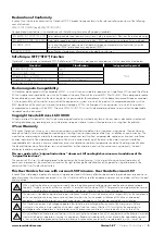
Page 3: ...of delivery installation or commissioning The manufacturer also accepts no liability for damage or consequences resulting from inappropriate negligent or incorrect installation incorrect adjustment of...

Page 4: ...Machinery In particular the machine manufacturer is responsible for ensuring that the electrical equipment complies with EN60204 1 and providing a disconnecting device which must be one of the follow...

Page 5: ...Guidelines for Mounting IP66 Units 12 12 13 16 17 17 18 5 Select the correct power and motor cables according to local wiring regulations or code noting the maximum permissible sizes 10 2 Input Output...

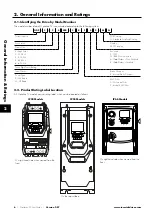
Page 6: ...me Size Voltage Code 2 230 Volt 4 400 Volt 5 525 Volt 6 600 Volt Enclosure 2 IP20 N IP55 Non Switched A IP66 Outdoor Non Switched B IP66 Outdoor Switched Three Digit Power Rating Input Phases Brake Ch...

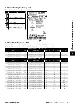
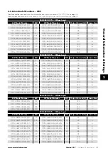
Page 7: ...5 ODP 2 22020 1HF42 MN 2 7 2 ODP 2 22220 1KF42 MN 2 2 ODP 2 22030 1HF42 MN 3 10 5 2 200 240V 10 3 Phase Input kW Model kW HP Model HP Output Current A Frame Size ODP 2 22075 3KF42 MN 0 75 ODP 2 22010...

Page 8: ...6B ODP 2 641 10 3KF42 MN 1 10 ODP 2 64175 3HF42 MN 175 202 6B ODP 2 84200 3KF42 TN 200 ODP 2 84300 3HF42 TN 300 370 8 ODP 2 84250 3KF42 TN 250 ODP 2 84400 3HF42 TN 400 450 8 500 600V 10 3 Phase Input...

Page 9: ...2 44220 3KF4N MN 22 ODP 2 44300 3HF4N MN 30 46 4 ODP 2 54300 3KF4N MN 30 ODP 2 54040 3HF4N MN 40 61 5 ODP 2 54370 3KF4N MN 37 ODP 2 54050 3HF4N MN 50 72 5 ODP 2 64045 3KF4N MN 45 ODP 2 64060 3HF4N MN...

Page 10: ...P Output Current A Frame Size ODP 2 24075 3KF4A MN 0 75 ODP 2 24010 3HF4A MN 1 2 2 2 ODP 2 24150 3KF4A MN 1 5 ODP 2 24020 3HF4A MN 2 4 1 2 ODP 2 24220 3KF4A MN 2 2 ODP 2 24030 3HF4A MN 3 5 8 2 ODP 2 2...

Page 11: ...Output Current A Frame Size ODP 2 24075 3KF4B MN 0 75 ODP 2 24010 3HF4B MN 1 2 2 2 ODP 2 24150 3KF4B MN 1 5 ODP 2 24020 3HF4B MN 2 4 1 2 ODP 2 24220 3KF4B MN 2 2 ODP 2 24030 3HF4B MN 3 5 8 2 ODP 2 244...

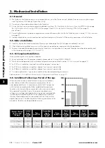
Page 12: ...be operated within an ambient temperature range as stated in section 10 1 Environmental on page 72 For IP20 units installation is required in a pollution degree 1 environment For IP55 units installat...

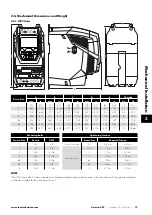
Page 13: ...1 25 320 12 59 578 22 75 200 7 87 32 70 5 6B 726 28 58 330 13 320 12 59 680 26 77 225 8 85 43 94 8 8 995 39 17 480 18 89 477 18 77 942 37 08 432 17 130 286 6 Mounting Bolts Tightening Torques Frame S...

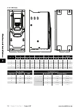
Page 14: ...270 10 63 515 20 28 175 6 89 23 50 7 6 865 34 06 330 12 99 330 12 99 830 32 68 200 7 87 55 121 2 7 1280 50 39 330 12 99 360 14 17 1245 49 02 200 7 87 89 196 2 Mounting Bolts Tightening Torques Frame...

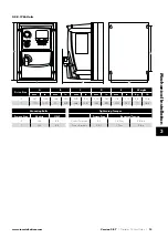
Page 15: ...mm in mm in kg Ib 2 257 10 12 188 7 40 239 9 41 200 7 87 178 7 01 4 8 10 6 3 310 12 20 21 1 8 29 266 10 47 252 9 90 200 7 87 7 7 16 8 Mounting Bolts Tightening Torques Frame Size Metric UNF Frame Size...

Page 16: ...or liquids conductive contaminants such as condensation carbon dust and metallic particles and sprays or splashing water from all directions High moisture salt or chemical content environments should...

Page 17: ...uitable flat blade screwdriver to pull the release tab downwards and lift the bottom of the drive away from the rail first 3 8 Guidelines for Mounting IP55 Units Before mounting the drive ensure that...

Page 18: ...table below must be observed The mounting site and chosen mountings should be sufficient to support the weight of the drives Using the drive as a template or the dimensions shown below mark the locat...

Page 19: ...uled maintenance program so that the installation maintains a suitable operating environment this should include Ambient temperature is at or below that set out in section 10 1 Environmental on page 7...

Page 20: ...information in section 4 2 on page 21 Isolator Disconnect Ensure there is at least 30 seconds between each power on Fuses Circuit Breaker Additional information in section 4 3 3 on page 22 External Li...

Page 21: ...age 22 Fuses Circuit Breaker Additional information in section 4 3 3 on page 22 External Line Reactor optional Additional information in section 4 3 4 on page 24 External EMC Filter optional Additiona...

Page 22: ...ation is correct i e L1 L1 L2 L2 L3 L3 failure to do so will result in a Ph Seq trip Ensure there is at least 30 seconds between each power on 4 3 1 Suitability All Optidrive P2 models are designed fo...

Page 23: ...cases the motor manufacturer should be consulted and preventative measures may be required prior to operating with the drive The motor should be connected to the Optidrive U V and W terminals using a...

Page 24: ...resistor the following settings are required Set P1 14 201 where 201 is the default password setting for advanced parameter access Enter the resistance of the brake resistor in P6 19 Ohms Enter the po...

Page 25: ...V DC Supply 100mA or External 24V DC Input 4 10 1 26 2 DI 1 Digital Input 1 Run Enable STOP RUN 4 10 2 26 3 DI 2 Digital Input 2 FORWARD REVERSE 4 10 2 26 4 DI 3 Digital Input 3 P1 12 Reference Preset...

Page 26: ...d by parameters P1 12 and P1 13 The function of these parameters and available options are described in section 7 Control Terminal Functions on page 40 Local Potentiometer Connection AI1 2 wire Analog...

Page 27: ...show IP66 Switch Setup 2 Pos DI1 Pos DI2 1 Switch disabled 0 Pos DI1 Pos DI1 2 5 Use UP or DOWN key to select the option 0 Pos DI1 Pos DI1 2 means integrated switches are enabled 1 Switch disabled me...

Page 28: ...st Practice use 360 bonding EMC cable gland shielded to motor chassis 4 13 2 Recommended Cable Types by EMC Category Number of Input Phases Rated Supply Voltage Frame Size IP rating Maximum Motor Cabl...

Page 29: ...trol panel backplate using a suitable EMC clamp or gland fitted as close to the drive as possible The drive earth terminal must also be connected directly to this point using a suitable cable which pr...

Page 30: ...s from being present at the drive power terminals 1 NOTE The STO function does not prevent the drive from an unexpected re start As soon as the STO inputs receive the relevant signal it is possible su...

Page 31: ...ive not healthy is less than 20ms 4 14 7 STO Electrical Installation The STO wiring shall be protected from inadvertent short circuits or tampering which could lead to failure of the STO input signal...

Page 32: ...ration this should include the following tests With the motor at standstill and a stop command given to the drive as per the start source method selected in P1 13 o De energise the STO inputs Drive wi...

Page 33: ...grammed only in internal PLC function block Start Button When in Hand mode used to Start the drive Stop Reset Button Used to reset a tripped drive When in Keypad mode used to Stop the drive P2 01 Driv...

Page 34: ...key for 1 second The display will show the motor power kW If P1 10 0 pressing the Navigate key for 1 second will display the motor speed RPM 5 3 Additional Display Messages Auto Tuning in Progress Ex...

Page 35: ...m the drive memory the following procedure is used Factory Parameter Reset User Parameter Reset P2 01 P2 01 P2 01 P2 01 P2 01 P2 01 Stop P Def Stop Stop U Def Stop 15kW 400V 3Ph 50 0Hz 15kW 400V 3Ph P...

Page 36: ...requency Speed limit Maximum frequency Speed limit 1500 rpm 0 rpm P1 01 7500 rpm 0 rpm P1 01 7500 rpm 0 rpm Whilst editing a parameter value press the Up and Down keys simultaneously The parameter wil...

Page 37: ...ng with the first 50 parameters in Group 0 P1 14 P6 30 Default setting 201 With this setting all parameters are accessible 6 2 Parameter Group 1 Basic Parameters The basic parameter group allows the u...

Page 38: ...26 should be enabled In this mode the drive brake transistor where fitted is disabled 2 Ramp brake chopper enabled When the enable signal is removed the drive will ramp to stop with the rate controll...

Page 39: ...sed on the motor parameters measured during an autotune P1 12 Primary Command Source 0 6 0 0 Terminal Control The drive responds directly to signals applied to the control terminals 1 Keypad control u...

Page 40: ...e is fitted control is through the Modbus RTU interface Digital Input 1 must be closed to allow operation 5 Slave Mode Master Drive From Master Optidrive P2 provides an inbuilt Master Slave function A...

Page 41: ...taneously the drive stops using Fast Stop Ramp Time P2 25 FAST STOP P2 25 Normally Closed Falling Edge Open momentarily to FAST STOP the drive using Fast Stop Ramp Time P2 25 E TRIP Normally Closed Ex...

Page 42: ...ff P2 01 REF On Off P2 02 REF Off On P2 03 REF On On P2 04 REF 8 STOP RUN FWD REV DI3 DI4 Preset Speed DECEL P1 04 DECEL P8 1 1 Off Off P2 01 REF On Off P2 02 REF Off On P2 03 REF On On P2 04 REF 9 ST...

Page 43: ...the Selected Speed Reference 7 3 Example Connection Schematics P1 13 Setting 1 4 11 14 _ 24 V DC 1 24V DC 24V DC 24V DC 24V DC 24V DC 2 DI 1 Disable Enable Disable Enable Run Forward Run Forward 3 DI...

Page 44: ...Ramp Select P1 04 P8 11 Dec Ramp Select P1 04 P8 11 P1 12 Reference Preset Ref 11 AO 2 Analog Output 2 Motor Current Analog Output 2 Motor Current Analog Output 2 Motor Current Analog Output 2 Motor...

Page 45: ...tput 2 Motor Current Analog Output 2 Motor Current 12 STO STO STO 13 STO STO STO P1 13 Setting 7 17 _ 24 V DC 1 24V DC 24V DC 24V DC 2 DI 1 Disable Enable Run Forward 3 DI 2 Forward Reverse Run Revers...

Page 46: ...COM 0V COM 10 DI 5 P1 12 Reference P2 01 Reference P1 12 Reference P2 01 Reference 11 AO 2 Analog Output 2 Motor Current Analog Output 2 Motor Current 12 STO STO STO 13 STO STO STO P1 13 Setting 21 _...

Page 47: ...in P1 03 and P1 04 respectively and will not hold any output frequency within the defined band If the frequency reference applied to the drive is within the band the Optidrive output frequency will re...

Page 48: ...to10V 10 to 0V 0 to 20mA 20 to 0mA 4 to 20mA 20 to 4mA P2 15 Relay 1 Function 0 14 1 Setting Function Logic 1 when 0 Drive running The Optidrive is enabled Running 1 Drive healthy No fault or trip co...

Page 49: ...ic 0 when the signal falls below the value programmed in P2 17 P2 19 Relay 2 Analog Output 2 Upper Limit P2 20 200 0 100 0 P2 20 Relay 2 Analog Output 2 Lower Limit 0 0 P2 19 0 0 Used in conjunction w...

Page 50: ...P2 28 P2 30 Analog Input 1 Terminal 6 Format See Below Setting Signal Format 0 to 10 Volt Signal Uni polar 10 to 0 Volt Signal Uni polar 10 to 10 Volt Signal Bi polar 0 to 20mA Signal 4 to 20mA Signal...

Page 51: ...red for multiple speed references typically Hand Auto control or Local Remote control when switched to keypad mode by a digital input the drive will continue to operate at the last operating speed 3 P...

Page 52: ...he PID Controller Where the feedback is provided from a transducer such as a pressure transducer or level measurement this represents the percentage of the pressure range e g for a 0 10 Bar transducer...

Page 53: ...the simplest control and is suitable for a wide range of applications Sensorless Vector Torque Control o This method is suitable for specific applications only which require the motor torque to be th...

Page 54: ...cy or speed Some motors may provide a value for volts per thousand RPM and it may be necessary to calculate the correct value for P1 07 o P1 08 Motor Rated Current o P1 09 Motor Rated Frequency o Opti...

Page 55: ...can tolerate higher values of proportional gain and high inertia low friction loads may require the gain to be reduced P4 04 Vector Speed Controller Integral Time Constant 0 010 2 000 0 050 s Sets th...

Page 56: ...lly this provides counter clockwise rotation of the motor P4 14 Thermal Overload Reaction 0 1 0 0 Trip When the overload accumulator reaches the limit the drive will trip on It trp to prevent damage t...

Page 57: ...U Communications on page 65 8 3 5 CAN Open Connection Optidrive P2 supports CAN Open communication Connection is made through the RJ45 connector For further information refer to section 9 3 CAN Open C...

Page 58: ...Group 9 In this case User Register 4 should not be written to within any PLC function code although the value can be read P5 14 Fieldbus PDI 3 Function Select 0 2 0 0 Torque reference limit This optio...

Page 59: ...s 0s P6 13 Hoist Brake Release Time 0 0 5 0s 0 2s P6 14 Hoist Brake Apply Time 0 0 5 0s 0 3s P6 15 Hoist Brake Pre Torque Level 0 0 200 0 8 0 P6 16 Hoist Pre Torque Time Limit 0 0 25 0s 5 0s P6 17 Max...

Page 60: ...n Vector control modes P7 14 Low Frequency Torque Boost 0 0 100 0 0 0 For PM Motors applies a torque boost current at low frequency x P1 08 P7 15 Torque Boost Frequency Limit 0 0 50 0 0 0 For PM motor...

Page 61: ...9 21 Preset Speed Select Input 0 P9 22 Preset Speed Select Input 1 P9 23 Preset Speed Select Input 2 P9 24 Acceleration Ramp Select Bit 0 P9 25 Acceleration Ramp Select Bit 1 P9 26 Deceleration Ramp B...

Page 62: ...Rs P0 18 Motor Stator Inductance Ls H P0 19 Motor Rotor Resistance Rr P0 20 DC Bus Voltage V P0 21 Heatsink Temperature C P0 22 Time Left To Next Service Hours P0 23 Time Heatsink 85 C HH MM SS P0 24...

Page 63: ...P0 58 Encoder Feedback Speed Hz RPM P0 59 Frequency Input Speed Hz RPM P0 60 Calculated Slip Speed Hz RPM P0 61 Relay Speed Hysteresis Hz RPM P0 62 Droop speed Hz RPM P0 63 Post ramp speed reference...

Page 64: ...Modbus RTU or CANopen ensure that the 0V signal T3 is also used to avoid comms errors and potentially damaging common mode voltages The Optibus data link is only used for connection of Invertek periph...

Page 65: ...e noise 9 2 Modbus RTU Communications 9 2 1 Modbus Telegram Structure The Optidrive P2 supports Master Slave Modbus RTU communications using the 03 Read Multiple Holding Registers and 06 Write Single...

Page 66: ...ent of a drive trip Refer to section 1 1 1 Fault Messages for a list of fault codes and diagnostic information 7 Output Frequency R Output frequency of the drive to one decimal place e g 123 12 3 Hz 8...

Page 67: ...agement Sync 080h Synchronous message COB ID can be configured to other value Emergency 080h Node address Emergency message COB ID can be configured to other value PDO1 TX 180h Node address Process da...

Page 68: ...modes can be selected for each PDO For RX PDO the following modes are supported Table 3 RX PDO Transmission Mode Transmission Type Mode Description 0 240 Synchronous The received data will be transfer...

Page 69: ...ned 32 N 00000580h Node ID 1400h 0 RX PDO1 comms param No of entries RO Unsigned 8 N 2 1 RX PDO1 COB ID RW Unsigned 32 N 40000200h Node ID 2 RX PDO1 transmission type RW Unsigned 8 N 254 1401h 0 RX PD...

Page 70: ...0Bh 0 Motor speed Hz RO Unsigned 16 Y 500 50 0Hz 200Dh 0 Motor current RO Unsigned 16 Y 123 12 3A 200Eh 0 Motor torque RO Integer 16 Y 4096 100 0 200Fh 0 Motor power RO Unsigned 16 Y 1234 12 34kW 2010...

Page 71: ...9 8 7 6 5 4 3 2 1 0 0 Normal Operation Stop 1 Coast Stop Reset Fast Stop Run Object 200Ah Drive Status Register Status Bit 15 14 13 12 11 10 9 8 7 6 5 4 3 2 1 0 0 Drive Trip Code No Function Drive Hea...

Page 72: ...rrent at the incoming supply voltage Please note that the maximum cable length stated in the following tables indicate the maximum permissible cable length for the drive hardware and does not take int...

Page 73: ...Resistance kW HP A Non UL UL mm AWG kcmil A m ft 2 0 75 1 3 5 6 6 8 8 2 2 100 330 400 2 1 5 2 5 6 10 10 8 8 4 1 100 330 200 2 2 2 3 7 5 10 10 8 8 5 8 100 330 150 2 4 5 1 1 5 16 15 8 8 9 5 100 330 100...

Page 74: ...or Ambient Temperature The drive is protected against short circuit from power output to protective earth for all rated cable lengths cable sizes and cable types 3 phase drive can be connected to sing...

Page 75: ...2 Input Output Power and Current Ratings Suitable Power and motor cables should be selected according to the data shown in section 10 2 Input Output Power and Current Ratings Power cable connections a...

Page 76: ...2 5 12 5 7 1 Amps x 87 5 6 2 Amps Now apply the derating for altitude above 1000 metres 1 per 100m above 1000m 10 x 1 10 7 9 Amps x 90 5 5 Amps continuous current available If the required motor curr...

Page 77: ...units have EMC Filter disconnection points only located on the front face of the unit as shown Frame Size 6A 6B Frame Size 6A 6B units have EMC Filter disconnection points only located on the front fa...

Page 78: ...1 09 If operating in Vector mode P4 01 0 or 1 also check the motor power factor in P4 05 and ensure an autotune has been successfully completed for the connected motor Check the load mechanically to e...

Page 79: ...re The connected motor PTC device has caused the drive to trip 22 Cooling Fan Fault Check and if necessary replace the drive internal cooling fan 23 Ambient Temperature High The measured temperature a...

Page 80: ...to the power rating of the connected drive 45 Incorrect Supply Phase Sequence Applies to Frame Size 8 drives only indicates that the incoming power supply phase sequence is incorrect Any 2 phases may...

Page 81: ...ency Classification Please scan the QR code or visit www invertekdrives com ecodesign to learn more about the Ecodesign Directive and for specific product efficiency classification and part load loss...

Page 82: ...82 Optidrive P2 User Guide Version 3 07 www invertekdrives com...

Page 83: ...Version 3 07 Optidrive P2 User Guide 83 www invertekdrives com...

Page 84: ...82 P2MAN IN_V3 078 82 P2MAN IN_V3 07 Invertek Drives Ltd Offa s Dyke Business Park Welshpool Powys SY21 8JF United Kingdom Tel 44 0 1938 556868 Fax 44 0 1938 556869 www invertekdrives com...

Reviews: