background image


MAGNETIC ELLIPTICAL TRAINER 

SF-E3416 

USER MANUAL 


IMPORTANT:  Please  read  this  manual  carefully  before  using  the  product. 
Retain owner’s manual for future reference. For Customer Service, please 
contact: 

support@sunnyhealthfitness.com


Summary of Contents for SF-E3416

Page 1: ...PTICAL TRAINER SF E3416 USER MANUAL IMPORTANT Please read this manual carefully before using the product Retain owner s manual for future reference For Customer Service please contact support sunnyhealthfitness com ...

Page 2: ...ldren and pets away from the equipment The equipment is designed for adult use only 4 Use the equipment on a solid flat level surface with a protective cover for your floor or carpet To ensure safety the equipment should have at least 2 feet of free space all around it 5 Ensure that all nuts and bolts are securely tightened before using the equipment The safety of the equipment can only be maintai...

Page 3: ... 46 47 46 49 50 31 32 33 33 37 38 20 21 24 23 22 21 52A 53 29 25R 11 60 60 41 60 61 30 36 21 60 60 70 39 39 32 33 33 35 25L 41 41 60 61 48 49 46 46 70 40 17 56 63 41 44 62 56 63 34 16 62 43L 43R 55 55 64 54 54 54 54 35 47 66 67 68 69 1 27 28 28 51 51 65 19 29 19 29 57 58 59 29 19 17 19 18 42 26 26 38 63 38 56 37 37 71 52B ...

Page 4: ...edal 2 14 End cap 28 32 50 2 44 Bolt M10 50 13 S17 2 15 Screw M5 10 2 45 Hinge bolt L 16 89 23 1 2 S8 1 16 Bushing 32 25 L83 2 46 Alloy bushing 18 3 14 7 10 1 4 17 Bolt M8 40 20 S14 Grade A 6 47 Link connector combination 2 18 Arc washer d8 20 2 R16 2 48 Nylon nut R 1 2 20 H8 S19 1 19 Nut M8 H16 S13 6 49 Spring washer 1 2 2 20 Long spacer 32 19 2 75 5 2 50 Nylon nut L 1 2 20 H8 S19 1 21 Alloy wrap...

Page 5: ...ly remove the hardware and reinstall the hardware as assembly is required No Description Qty No Description Qty 60 Ball cap S13 66 Allen wrench S8 1 61 Ball cap S18 6 67 Allen wrench S6 1 62 Ball cap S16 2 68 Spanner S13 14 15 1 63 Nylon nut M10 H9 5 S17 2 69 Spanner S17 S19 inner 17 1 64 Handlebar post 4 70 Wave washer d17 25 0 3 2 65 Rear stabilizer 1 71 Computer wire 1 ...

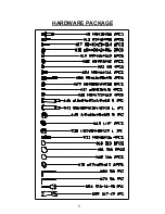
Page 6: ...5 HARDWARE PACKAGE ...

Page 7: ...nd Rear Stabilizers No 27 and No 65 to the Main Frame No 59 using 4 Carriage Bolts No 28 4 Arc Washers No 29 and 4 Nuts No 19 tighten with Spanner No 68 28 M8 60 20 H5 4pcs 29 d8 20 2 R30 4pcs 19 M8 H16 S13 4pcs 27 28 28 65 19 29 19 57 29 19 29 59 58 ...

Page 8: ...f resistance this will provide the tension cable with the necessary length required to connect it Connect the Upper Sensor Wire No 10 to the Lower Sensor Wire No 58 Then connect the Tension Cable No 52B to the Tension Wire No 57 Next attach the Handlebar Post No 64 to the Main Frame No 59 using 4 Screws No 53 and 4 Arc Washers No 29 tighten with Allen Wrench No 67 ...

Page 9: ...e Washer No 70 1 Spring Washer No 49 and Nylon Nut L No 50 tighten with Allen Wrench No 66 and Spanner No 69 Repeat this process to assemble the right side IMPORTANT NOTICE The left Hinge Bolt L No 45 has reverse threading when assembling the left side you must screw Hinge Bolt L counter clockwise to tighten When assembling the right side screw Hinge Bolt R No 40 clockwise to tighten 45 49 50 61 µ...

Page 10: ...Spring Washers No 49 Nylon Nut L No 50 and Nylon Nut R No 48 and attach the Ball Caps No 61 You can now reattach the Link Connector Combination No 47 to the Connecting Rod No 55 IMPORTANT The Left and Right Hinge Bolts No 45 and No 40 must fully penetrate the Link Connector Combination No 47 and crank This will ensure the stability and durability of your Elliptical Trainer To install the hinge bol...

Page 11: ...EP 4 Attach the left and right Pedals No 43L R to the Connecting Rods No 55 using 4 Bolts No 17 4 Washers No 37 and 4 Nylon Nuts No 38 tighten and secure with Spanner No 68 Φ 55 43L 17 55 37 38 43R 17 37 38 ...

Page 12: ...nsert the left and right Handlebars No 13L R into the left and right Swing Rods No 24L R fix using 2 Bolts No 17 2 Arc Washers No 18 and 2 Nuts No 19 Tighten with Spanner No 68 13L 13R 18 17 19 18 25L 25R 19 17 µ ...

Page 13: ...len Wrench No 67 then cover the clamp using Clamp Cover No 42 Connect the Upper Sensor Wire No 10 to the Computer Wire No 71 Then using 2 Screws No 15 attach the Computer No 1 to the computer bracket located on the top of Handlebar Post No 64 Tighten with Spanner No 68 Insert the Handle Pulse Wire No 9 into the socket located on the back of the Computer No 1 Assembly is complete ...

Page 14: ...etting press the MODE key when the pointer on the function you wish to select begins to blink once locked only the selected function will be displayed 4 FUNCTIONS TIME Counts the total time of an exercise from start to finish SPEED Displays the current speed being obtained DISTANCE Counts the total distance of an exercise from start to finish CALORIES Counts the total amount of calories burned dur...

Reviews: