
Sunrise Medical 2842 N. Business Park Ave Fresno, CA 93727 USA
© 2022 Sunrise Medical (US) LLC
07/2022 253772 Rev. A Page 1of2
Customer Service: +1(800) 333-4000
or visit www.SunriseMedical.com
R90
™
SHROUD REPLACEMENT
™
™
Please read these instructions carefully before beginning the assembly. Failure to understand and
follow assembly instructions may result in injury to technician and/or end user and may void the
warranty. If you have any questions call Sunrise Medical Technical Support at +1(800) 333-4000.
Before beginning the shroud replacement,
ensure you heed the following warnings.
WARNING
Minimal electronics experience is required to
complete Shroud Replacement.
WARNING
Ensure your work surface is free of any build up
of liquids and/or static electricity. Touch a metal
surface to discharge static electricity prior to
touching the PCB (Printed Circuit Board).
WARNING
Limit touching of the PCB to outer edges with as
light a touch as possible, minimizing pressure on
the PCB.
WARNING
If the PCB must remain outside of the enclosure,
place it in a static protective bag until ready for
reassembly.
WARNING
Attach the ground cord from the ESD
(Electrostatic Discharge) Field Kit to the
uncoated metal shown in Figure 1. Follow all
instructions provided in the ESD Field Kit to
ensure not to damage the PCB.
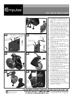
1.
To remove skid plate (B), use an M2 Allen
wrench to remove screws (A). (Fig. 1)
2.
To remove battery plate hardware, use
a T-20 t-handle to remove torx screws (C)
and loosen the battery plate (Fig. 2)
3.
To loosen PCB mounting hardware, use a
T-15 t-handle to loosen screw (D). (Fig 3)
4.
To remove hardware on side of shroud, use
a T-20 t-handle to remove screws (E).
(Fig. 4)
5.
To remove hardware on front of shroud,
use a M4 Allen wrench to remove socket
head screws (F). (Fig. 5)
6.
To remove the left shroud, disconnect the
charger port harness (G). Then, remove the
shroud. (Fig. 6)
Note: If replacing the left shroud only,
reverse the order of steps 1-6 to fi t the new
left shroud. Before tightening the hardware
ensure you line up the shroud and the PCB,
fi tting the PCB into the shroud slot (H).
(Fig. 6)
Tools required
1. Allen wrench, sizes: 2mm, 4mm
2. Flat head screw driver
3. T-handle, sizes: T-15, T-20
4. ESD (Electrostatic Discharge)
Field Kit 8501 or 8507
DEALER/TECHNICIAN WARNING
Attention dealers and qualifi ed technicians, do not operate or service this device without fi rst reading the owners manual. If you
do not understand the instructions and warnings in the owners manual please contact the Sunrise Medical Technical Service
Department before operating and/or servicing the Empulse device. Failure to do so may result in damage and/or injury.
Find more information and important warnings see the device owner’s manual or at: www.SunriseMedical.com.
2
C
4
E
3
D
5
F
6
G
H
A
B
ESD CLIP ON
UNCOATED
METAL
1


