Supermicro CSE-LB13-AW Series, User Manual
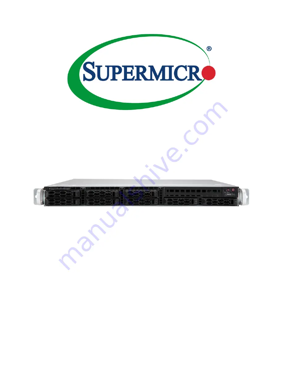
The Supermicro CSE-LB13-AW Series is a top-of-the-line server chassis perfect for hosting your data center. Ensure optimal performance by downloading the free user manual from 88.208.23.73:8080. This comprehensive manual provides detailed instructions on setup, maintenance, and troubleshooting, helping you get the most out of your equipment.
Share
Download

Reviews:
No comments


