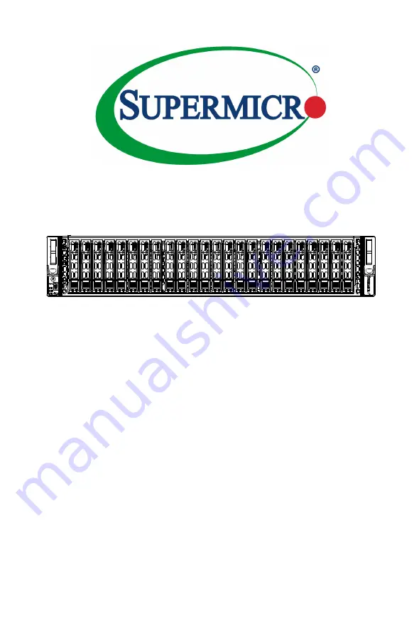
Supermicro SC216 Series, User Manual
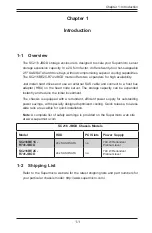
The Supermicro SC216 Series is a high-quality server chassis designed for maximum performance and efficiency. Ensure optimal use of your equipment by downloading the free User Manual from 88.208.23.73:8080. This manual provides essential information for setup and maintenance, ensuring seamless operation of your system.
Share
Download

Reviews:
No comments
Related manuals for SC216 Series
NI PXI-1044
Brand: National Instruments Pages: 63

SC748TQ-R1200B
Brand: Supero Pages: 94

XACT PRO 7448
Brand: WP Pages: 30

CNRACKX
Brand: Crestron Pages: 34

Hotwire 8774
Brand: Paradyne Pages: 110

TXP5016
Brand: THORLABS Pages: 44

Summit Virtual
Brand: Extreme Networks Pages: 22

Falcon 4010
Brand: H3 Pages: 24
ChromaFlex
Brand: ATX Pages: 90

EMC PowerEdge MX7000
Brand: Dell Pages: 68

LC7.2E
Brand: Philips Pages: 111

LC4.41A AA
Brand: Philips Pages: 87

TE1.1E
Brand: Philips Pages: 46

TES1.0E LA
Brand: Philips Pages: 76

TPN15.2E LA
Brand: Philips Pages: 71

VES1.1E
Brand: Philips Pages: 79

LC8.1E
Brand: Philips Pages: 71

TPM16.1E LA
Brand: Philips Pages: 69


