background image

SC721 CHASSIS SERIES

SC721TQ-250B

USER’S MANUAL


1.0

Summary of Contents for SC721TQ-250B

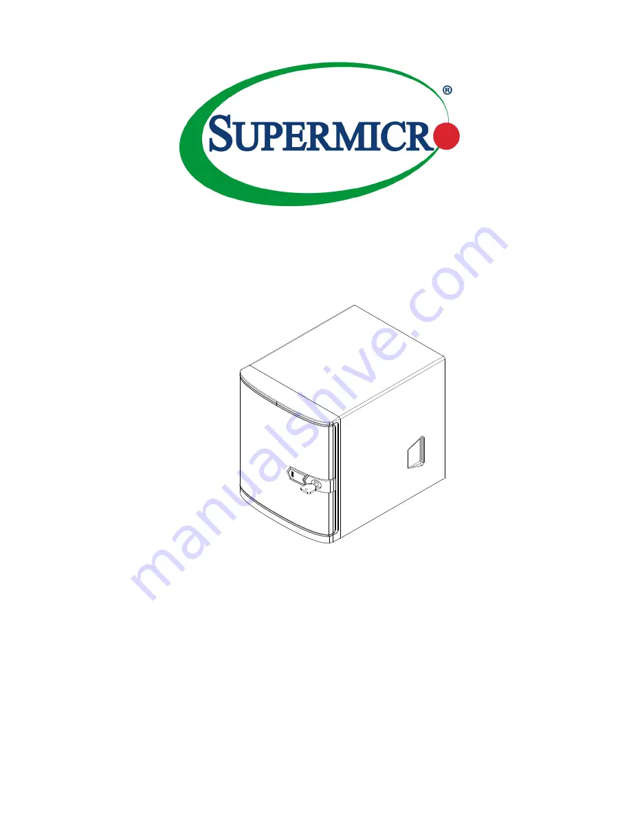
Page 1: ...SC721 CHASSIS SERIES SC721TQ 250B USER S MANUAL 1 0...

Page 2: ...ARE OR DATA STORED OR USED WITH THE PRODUCT INCLUDING THE COSTS OF REPAIRING REPLACING INTEGRATING INSTALLING OR RECOVERING SUCH HARDWARE SOFTWARE OR DATA Any disputes arising between manufacturer and...

Page 3: ...tenance should be performed by experienced technicians only The SC721 chassis is a compact 9 45 tall mini tower chassis with rich feature sets It supports a wide range of Mini ITX motherboards from th...

Page 4: ...hly familiarize yourself with the safety precautions before installing and servicing this chassis Chapter 3 System Interface Refer to this chapter for details on the system interface which includes th...

Page 5: ...5 Power Disconnection Warning 2 6 Equipment Installation 2 8 Restricted Area 2 9 Battery Handling 2 10 Redundant Power Supplies 2 12 Backplane Voltage 2 13 Comply with Local and National Electrical C...

Page 6: ...alling the Side Mounted Fixed Hard Drive 5 7 5 7 Installing the I O Shield and Motherboard 5 8 I O Shield and Motherboard Installation 5 8 5 8 Hardware Security 5 10 Front Bezel Lock 5 10 Rear Chassis...

Page 7: ...ple optimized cooling for FB DIMM memory modules and four hot swap drive bays offer maximum storage capacity Default Design for 84W TDP CPU 1 2 Shipping Lists Please visit the following link for the l...

Page 8: ...Address Super Micro Computer B V Het Sterrenbeeld 28 5215 ML s Hertogenbosch The Netherlands Tel 31 0 73 6400390 Fax 31 0 73 6416525 Email sales supermicro nl General Information support supermicro n...

Page 9: ...ust be mailed when service is complete For faster service RMA authorizations may be requested online http www super micro com support rma Whenever possible repack the chassis in the original Supermicr...

Page 10: ...SC721 Chassis Manual 1 4 Notes...

Page 11: ...nt for assistance Only certified technicians should attempt to install or configure components Read this appendix in its entirety before installing or configuring components in the Supermicro chassis...

Page 12: ...e los riesgos de la corriente el ctrica y familiar cese con los procedimientos est ndar de prevenci n de accidentes Al final de cada advertencia encontrar el n mero que le ayudar a encontrar el texto...

Page 13: ...k letsel kan veroorzaken Voordat u aan enige apparatuur gaat werken dient u zich bewust te zijn van de bij een elektrische installatie betrokken risico s en dient u op de hoogte te zijn van de standaa...

Page 14: ...Systems an die Stromquelle die Installationsanweisungen lesen Advertencia Lea las instrucciones de instalaci n antes de conectar el sistema a la red de alimentaci n Attention Avant de brancher le sys...

Page 15: ...ert ist Stellen Sie sicher dass der Nennwert der Schutzvorrichtung nicht mehr als 250 V 20 A betr gt Advertencia Este equipo utiliza el sistema de protecci n contra cortocircuitos o sobrecorrientes de...

Page 16: ...ystemsbestandteile anzubringen oder zu entfernen Warning The system must be disconnected from all sources of power and the power cord removed from the power supply module s before accessing the chassi...

Page 17: ...nentes de sistema Attention Le syst me doit tre d branch de toutes les sources de puissance ainsi que de son cordon d alimentation secteur avant d acc der l int rieur du chassis pour installer ou enle...

Page 18: ...s Installieren Ersetzen oder Bedienen dieser Ausr stung sollte nur geschultem qualifiziertem Personal gestattet werden Advertencia Solamente el personal calificado debe instalar reemplazar o utilizar...

Page 19: ...stallation in Bereichen mit beschr nktem Zutritt vorgesehen Der Zutritt zu derartigen Bereichen ist nur mit einem Spezialwerkzeug Schloss und Schl ssel oder einer sonstigen Sicherheitsvorkehrung m gli...

Page 20: ...uivalent type recommended by the manufacturer Dispose of used batteries according to the manufacturer s instructions Waarschuwing Dit apparaat is bedoeld voor installatie in gebieden met een beperkte...

Page 21: ...ecommand e par le fabricant Jeter les piles usag es conform ment aux instructions du fabricant Advertencia Existe peligro de explosi n si la bater a se reemplaza de manera incorrecta Reemplazar la bat...

Page 22: ...ntes de alimentaci n Para cortar por completo el suministro de energ a deben desconectarse todas las conexiones Attention Cette unit peut avoir plus d une connexion d alimentation Pour supprimer toute...

Page 23: ...ero es peligroso Tenga cuidado cuando lo revise Attention Lorsque le syst me est en fonctionnement des tensions lectriques circulent sur le fond de panier Prendre des pr cautions lors de la maintenanc...

Page 24: ...codes Warnung Die Installation der Ger te muss den Sicherheitsstandards entsprechen Advertencia La instalacion del equipo debe cumplir con las normas de electricidad locales y nacionales Backplane Wa...

Page 25: ...ional laws and regulations Attention L quipement doit tre install conform ment aux normes lectriques nationales et locales Waarschuwing Bij installatie van de apparatuur moet worden voldaan aan de lok...

Page 26: ...odas las leyes y reglamentos nacionales Attention La mise au rebut ou le recyclage de ce produit sont g n ralement soumis des lois et ou directives de respect de l environnement Renseignez vous aupr s...

Page 27: ...dedos los destornilladores y todos los objetos lejos de las aberturas del ventilador Attention Il est possible que les ventilateurs soient toujours en rotation lorsque vous retirerez le bloc ventilat...

Page 28: ...ann zu einer Fehlfunktion oder ein Brand entstehen Elektrische Ger te und Material Safety Law verbietet die Verwendung von UL oder CSA zertifizierte Kabel UL oder CSA auf der Code f r alle anderen ele...

Page 29: ...utres appareils lectriques que les produits d sign s par Supermicro seulement AC AC UL CSA UL CSA UL CSA Supermicro UL CSA AC Electrical Appliance and Material Safety Law UL CSA UL CSA Waarschuwing Bi...

Page 30: ...2 20 SC721 Chassis Manual Notes...

Page 31: ...below Four hot swappable 3 5 hard drives Two internal fixed 2 5 hard drives Motherboard Support Supports a wide range of Mini ITX motherboards from ATOM to Core i7 Power Supply Each chassis includes a...

Page 32: ...npacking the System Inspect the box in which the chassis was shipped and note if it was damaged If the chassis itself shows damage file a damage claim with the carrier 3 3 Where to Get Replacement Com...

Page 33: ...includes a control panel which is located on the front of the chassis behind the front bezel that houses power buttons and status monitoring lights These elements are described in this chapter with po...

Page 34: ...ance tasks Reset The reset button is located below the power button and allows you to manu ally reset the system 4 3 Control Panel LEDs There are four control panel LEDs that provide status informatio...

Page 35: ...ake sure all fans are present and operat ing normally 4 Verify that the heatsinks are installed properly Informational LED Status Description Solid red An overheat condition has occured This may be ca...

Page 36: ...SC721 Chassis Manual 4 4 Notes...

Page 37: ...s screwdriver 5 2 Removing Power from the System Before performing some setup or maintenance tasks use the following procedure to ensure that power has been removed from the system 1 Use the operating...

Page 38: ...ey counterclockwise and open up the front bezel 3 Remove the three screws securing the cover to the chassis and set them aside for later use 4 Slide the cover toward the rear of the chassis 5 Lift the...

Page 39: ...s can be removed from the chassis without powering down the system Removing 3 5 Hot Swap Hard Drives 1 Unlock the front bezel and swing it open 2 Press the release tab on the hard drive carrier this w...

Page 40: ...dummy drive from the hard drive carrier 3 Install a new hard drive into the hard drive carrier with the printed circuit board side facing down so that the mounting holes in the drive align with those...

Page 41: ...ge sliding it towards the back of the the hard drive cage until it clicks into a locked position 3 Use the drive carrier handle to push the hard drive and hard drive carrier into the chassis hard driv...

Page 42: ...he power cord into the rear of the power supply as described in Section 5 2 and remove the chassis cover as de scribed in Section 5 3 2 Place the 2 5 hard drive into the hard drive bracket and secure...

Page 43: ...ed in Section 5 2 and remove the chassis cover as de scribed in Section 5 3 2 Place the 2 5 hard drive into the hard drive bracket and secure the hard drive to the bracket with the four screws provide...

Page 44: ...ts in place Install the I O shield before you install the motherboard Removing the Rear Tray 1 Review the documentation that came with the motherboard Become familiar with component placement requirem...

Page 45: ...eld into the opening in the rear of the chassis 3 Once installed the motherboard will hold the I O shield in place 4 Slide the tray back into the rear of the chassis 5 Plug the power cord into the rea...

Page 46: ...se Front Bezel Lock The SC721 has a locking front bezel to protect against unauthorized removal of the hard drives Use the key provided to lock and unlock the bezel Always remove the key from the lock...

Page 47: ...features a Kensington cable slot or K slot This slot accepts a standard Kensington cable locking device not included Attach the loop end of the cable to a secure object then insert the device into th...

Page 48: ...Section 5 2 and remove the chassis cover as described in Section 5 3 2 Unlock the front bezel and swing it open 3 Remove the two screws securing the cover plate to the front of the chassis and set the...

Page 49: ...Optional Figure 5 15 Installing the DVD ROM Drive 6 Slide the DVD ROM drive into the chassis 7 If desired secure the DVD ROM drive with two screws as illustrated above 8 Replace the chassis cover plug...

Page 50: ...g the PCI slot cover over the PCI slot in the rear of the tray and set it aside for later use 4 Slide the PCI slot cover up and out of the PCI slot 5 Simultaneously slide the card and its bracket into...

Page 51: ...down the system and remove the power cord from the rear of the power supply as described in Section 5 2 and remove the chassis cover as described in Section 5 3 2 Align the mounting holes in the fan...

Page 52: ...5 2 and remove the chassis cover as described in Section 5 3 2 Remove the screws securing the power supply to the chassis which are located on the rear of the chassis Set these screws aside for later...

Page 53: ...ng the backplane mounting bracket to the chassis Set the screw aside for later use 3 Remove the backplane from the the chassis 4 Remove the screws securing the backplane to the backplane mounting brac...

Page 54: ...SC721 Chassis Manual 5 18 Notes...

Page 55: ...onfigurations For more compatible cables refer to the manufacturer of the motherboard and our Web site at www supermicro com A 2 Cables Included with SC721 Chassis SC721TQ 250B Part Type Quantity Desc...

Page 56: ...cribes the most commonly used screws Your chassis may not require all of the parts listed DVD ROM CD ROM and FLOPPY DRIVE Flat head 6 32 x 5 mm 0 197 Pan head 6 32 x 5 mm 0 197 Round head M3 x 5 mm 0...

Page 57: ...pply specifications for your chassis system The SC721 chassis includes a power supply rated at 80 Plus Bronze Level SC721TQ 250B 250W MFR Part PWS 251 1H AC Voltage 100 240V 50 60Hz 5 Amp 5V Max 14 Am...

Page 58: ...SC721 Chassis Manual B 2 Notes...

Page 59: ...prevent static discharge Touch a grounded metal object before removing a component from the antistatic bag Handle the backplane by its edges only do not touch its components peripheral chips memory mo...

Page 60: ...ers the most advanced functionality provided by the Serial Attached Serial Link industry in a slim package With the built in AMI MG 9071 chip the BPN SAS 733TQ Backplane allows the user to configure R...

Page 61: ...d on the backplane A built in overheat drive failure LED Indicator built in Temperature monitoring via a two wire I2 C temperature sensor in the MG 9071 chip The buzzer sound indicates that a conditio...

Page 62: ...R114 R116 R119 R120 R121 R122 R123 R124 R125 R126 R129 R130 R131 R132 R134 R135 R136 R137 JP29 U20 U23 JP44 C99 C100 C102 U25 C103 C104 C105 C107 C108 R144 M 37 M 38 U24 R149 C10 M 40 M 41 M 42 M 43...

Page 63: ...fan header uses DC power Default Fan disabled C 5 Front Connector Pin Definitions Backplane Main Power Connectors JP10 JP13 Pin Definitions Sideband Header JP51 1 Activity LED Header JP26 Pin Definiti...

Page 64: ...inition JP18 Open Default Normal Closed Buzzer reset JP26 Open Default Act 0 3 In JP29 Open Default Normal Closed MG9071 reset JP33 Pins 1 2 I2 C controller ID SGPIO Pins 2 3 Default I2 C controller I...

Page 65: ...0 SAS 1 SAS 2 SAS 3 Figure C 2 Rear View C 6 Rear Connectors and LED Indicators Rear connector and LED locations Rear Connectors Rear Connector Specification J1 Rear SAS 0 HDD Connected to HDD J2 Rear...

Page 66: ...Indicators Rear LED Indicators Specification D12 Rear SAS 0 Activity LED D13 Rear SAS 1 Activity LED D14 Rear SAS 2 Activity LED D15 Rear SAS 3 Activity LED D5 Rear SAS 0 Fail LED D6 Rear SAS 1 Fail L...

Page 67: ...C 9 Appendix C BPN SAS 733TQ Backplane Specifications Notes...

Page 68: ...reasonably expected to result in significant injury or loss of life or catastrophic property damage Accordingly Supermicro disclaims any and all liability and should buyer use or sell such products fo...

Reviews: