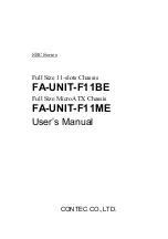
background image

USER’S MANUAL 

Revision 1.0

SC735D4 Chassis

Summary of Contents for SC735D4

Page 1: ...USER S MANUAL Revision 1 0 SC735D4 Chassis ...

Page 2: ... Class A device or in residential environment for Class B device This equipment generates uses and can radiate radio frequency energy and if not installed and used in accordance with the manufacturer s instruction manual may cause harmful interference with radio communications Operation of this equipment in a residential area is likely to cause harmful interference in which case you will be requir...

Page 3: ... provides information for the installation and use of the SC735D4 chassis Installation and maintenance should be performed by experienced technicians only This document lists compatible parts available when this document was published Refer to the Supermicro web site for updates on supported parts and configurations ...

Page 4: ...et Replacement Components 12 1 5 Returning Merchandise for Service 12 Chapter 2 Setup and Maintenance 2 1 Overview 13 Workstations Precautions 13 2 2 Removing Power from the System 13 2 3 Accessing the Chassis 14 Side Covers 14 Front Bezel 15 2 4 Storage Drives 17 Drive Cage 17 Removing and Installing Main Storage Drives 18 Top Front Peripheral Drive Bays 20 Removing and Installing Optional 2 5 St...

Page 5: ...5 Contents 2 8 Installing the Rear Input Output Shield and Motherboard 29 I O Shield 29 Motherboard 30 Appendix A Standardized Warning Statements for AC Systems Appendix B System Specifications ...

Page 6: ...m Europe Address Super Micro Computer B V Het Sterrenbeeld 28 5215 ML s Hertogenbosch The Netherlands Tel 31 0 73 6400390 Fax 31 0 73 6416525 Email sales supermicro nl General Information support supermicro nl Technical Support rma supermicro nl Customer Support Website www supermicro nl Asia Pacific Address Super Micro Computer Inc 3F No 150 Jian 1st Rd Zhonghe Dist New Taipei City 235 Taiwan R O...

Page 7: ...h a 90º rotatable drive cage and a high efficiency power supply CSE 735D4 1K26B 1200W power CSE 735D4 668B 668W power Key Features Kensington lock security Whisper quiet operation 21dB Seven full height full length expansion card slots Tool less 5 25 device installation One 12 cm PWM fan included 668W or 1200W power supply depending on model Supports E ATX ATX and microATX motherboard sizes ...

Page 8: ...l fixed cage Fans and Cooling The chassis includes one 12 cm PWM rear exhaust fan and supports an optional 12 cm front intake fan Motherboard The chassis accepts E ATX ATX and microATX form factor motherboards Expansion Slots Seven slots for PCI expansion cards are available on the chassis rear which can also be used for Graphic Processor Units GPUs External I O Connections The front of the chassi...

Page 9: ... 25 Drive Bays For optional DVD ROM drives or mobile rack module Control Panel Front control panel with Input output ports status indicators and a power button 1 3 Chassis Features Chassis Front The illustration below shows the features included on the front of the chassis Control Panel Lock 5 25 Drive Bays ...

Page 10: ...ar runs along the front of the chassis Control Panel Features Feature Description Power button The main power switch applies or removes primary power from the power supply to the server but maintains standby power HDD LED Indicates storage drive activity USB Two USB 3 0 ports and one USB 3 2 Gen2 10G TypeC port Audio and Mic Headphone jack and mic jack Power HDD LED USB USB USB Type C Audio Out Mi...

Page 11: ...r View Rear Features Features Description Power Supply One multi output 80Plus Platinum power supply Rear Exhaust Fan One 12 cm fan Rear I O Panel Details depend on the motherboard Expansion Slots Seven full height full length expansion slots Power supply may differ with configuration Power Supply Fan Expansion Slots Rear I O Ports ...

Page 12: ...er should be prominently displayed on the outside of the shipping carton and mailed prepaid or hand carried Shipping and handling charges will be applied for all orders that must be mailed when service is complete For faster service RMA authorizations may be requested online http www supermicro com support rma Whenever possible repack the chassis in the original Supermicro carton using the origina...

Page 13: ... to keep your system operating in case of a power failure Allow the power supply units and hot swap SATA drives to cool before touching them To maintain proper cooling always keep all chassis panels closed and all SATA carriers installed when not being serviced 2 2 Removing Power from the System Before performing most setup or maintenance tasks use the following procedure to ensure that power has ...

Page 14: ...the cover in place The chassis covers must be in place to allow proper airflow and prevent overheating Side Covers Removing the Side Covers Begin by powering down the system 1 Remove the screws two for the left three for the right at the rear of the chassis 2 Slide the cover toward the chassis rear and remove Figure 2 1 Removing the Side Covers ...

Page 15: ...he front bezel door can be opened to install the optional 5 25 drives or mobile racks for additional storage drives Also the entire bezel can be removed To open the bezel door unlock the lock and pull it open Figure 2 2 Opening the Bezel Door A Lock ...

Page 16: ... SC735D4 Chassis User s Manual Removing the Bezel 1 Remove the side covers 2 Find and remove the two rubber clasps from each side as shown below 3 Pull off the bezel Figure 2 3 Removing the Front Bezel Rubber Clasp ...

Page 17: ...internal drives below the rotating drive cage Drive Cage The drive cage rotates to access the drives Rotating the Drive Cage 1 Remove power from the system as described in Section 2 2 and remove the left side cover 2 Lift the release tab located at the top of the drive cage 3 Rotate the hard drive cage 90 degrees so the drive carriers are facing outward Figure 2 4 Rotating the Drive Cage Release T...

Page 18: ...age can house up to four drives of either 3 5 or 2 5 2 5 drives require an optional bracket MCP 220 73102 0N Removing and Installing Main Storage Drives 1 Remove power from the system remove the left side cover and rotate the drive cage 2 Disconnect the cables from the drive Figure 2 5 Installing Drives ...

Page 19: ...esent pull the sides of the carrier and remove the drive from the carrier 6 Insert a new drive into the carrier and push the sides of the carrier together 7 Slide the carrier into the cage until it clicks into place 8 If desired each carrier may be secured to the exterior of the drive cage using a screw 9 Rotate the cage 90 degrees inward 10 Connect the drive cables Figure 2 6 Drive Carrier Releas...

Page 20: ...ssis It supports two 5 25 drives or a mobile rack M14 or M28 containing hot swap 2 5 drives Installing the Top Front Drives or Mobile Rack 1 Power down the system unlock and open the front door 2 Install rail brackets onto the drive s or mobile rack as shown 3 Connect wiring to the system then slide the drive s or mobile rack into the bay Mounting Brackets ...

Page 21: ...Chapter 2 Setup and Maintenance 21 Figure 2 8 Installing an M28 Mobile Rack Figure 2 9 Installing an M14 Mobile Rack ...

Page 22: ...humb screw securing the drive cage to the chassis 3 Disconnect cables from the hard drives 4 Slide the drive cage out of the chassis 5 If a drive carrier is present press the release button and pull to remove it from the cage Figure 2 10 Installing Optional Cage and Drives Removing and Installing Optional 2 5 Storage Drives Thumb Screw ...

Page 23: ...m front intake fan is available Figure 2 11 Replacing the Rear Fan Exhaust Fan 6 Insert or replace the drive in the carrier 7 Insert the drive carrier into the cage sliding it towards the back of the cage until it clicks into a locked position 8 Slide the cage back into the chassis and tighten the thumb screw to secure the cage 9 Connect the drive cables re install the chassis cover and power up t...

Page 24: ... s Manual Optional Front Fan Front Fan An optional fan can provide increased cooling if needed This front fan and the optional internal 2 5 storage drives are mutually exclusive Figure 2 12 installing a Front Fan Rubber Pins Screws 2 5 ...

Page 25: ... into the mounting holes in the fan 3 Pull the rubber pins through the mounting holes of the system fan to secure the fan to the bracket 4 Insert the fan and bracket into the chassis aligning the holes at the top of the bracket with the holes in the chassis 5 Secure the fan to the chassis using the two screws provided 6 Connect the fan cable to the motherboard 7 Replace the chassis cover and power...

Page 26: ...he cover to detach and remove the cover completely 4 Remove the screws from the PCI slot cover as shown below 5 Remove the PCI shield from the slot you wish to populate 6 Insert the expansion card into the motherboard expansion slot while aligning the expansion card bracket with the opening in the rear of the chassis where the slot shield was removed 7 Secure the expansion card bracket to the rear...

Page 27: ...ower requirements of installed components in the system total no more than 80 of the power supply rating Installing a Power Supply 1 Power down the system as described in section 2 2 and open the left side chassis cover 2 The power supply is isolated from the rest of the system with a cover Remove the two screws at the top of this cover as shown below 3 Push in the release tabs along the bottom of...

Page 28: ...is 8 Position a new power supply in place reinstall the bracket and secure the unit to the chassis with the screws through the rear of the chassis 9 The 2000W power supply that comes standard with the SC735D4 is a modular type power supply that allows you to connect only the wiring you need for your system s configuration Attach all required wiring to the power supply then to your system as needed...

Page 29: ...hield This shield encloses the I O ports at the rear of the chassis Install it before installing the motherboard The motherboard package should include a compatible shield Installing the I O Shield 1 Open the chassis left side cover 2 With the illustrations facing outward place the shield into the space provided at the rear of the chassis ...

Page 30: ...e mounting base of the chassis Once all standoffs are in place you are ready to mount the motherboard Installing the Motherboard 1 Lay the motherboard on the chassis aligning the standoffs 2 Secure the motherboard to the standoffs using the rounded Phillips head screws Do not exceed eight inch pounds of torque 3 Secure the CPU heatsinks and other components to the motherboard as described in the m...

Page 31: ...onfiguring components in the Supermicro chassis These warnings may also be found on our website at http www supermicro com about policies safety_information cfm Warning Definition 警告の定義 この警告サインは危険を意味します 人身事故につながる可能性がありますので いずれの機器でも動作させる前に 電気回路に含まれる危険性に注意して 標準的な事故防止策に精通して下さい 此警告符号代表危险 您正处于可能受到严重伤害的工作环境中 在您使用设备开始工作之前 必须充分意识到触电 的危险 并熟练掌握防止事故发生的标准工作程序 请根据每项警告结尾的声明号码找到此设 备的安全性警告说明的翻译文本 此警告符號代表危險 您正處於可能...

Page 32: ... encontrará el número que le ayudará a encontrar el texto traducido en el apartado de traducciones que acompaña a este dispositivo GUARDE ESTAS INSTRUCCIONES IMPORTANTES INFORMATIONS DE SÉCURITÉ Ce symbole d avertissement indique un danger Vous vous trouvez dans une situation pouvant entraîner des blessures ou des dommages corporels Avant de travailler sur un équipement soyez conscient des dangers...

Page 33: ...okken risico s en dient u op de hoogte te zijn van de standaard procedures om ongelukken te voorkomen Gebruik de nummers aan het eind van elke waarschuwing om deze te herleiden naar de desbetreffende locatie BEWAAR DEZE INSTRUCTIES Installation Instructions Warning Read the installation instructions before connecting the system to the power source 設置手順書 システムを電源に接続する前に 設置手順書をお読み下さい 警告 将此系统连接电源前 请先阅...

Page 34: ... 연결하기 전에 설치 안내를 읽어주십시오 Waarschuwing Raadpleeg de installatie instructies voordat u het systeem op de voedingsbron aansluit サーキッ ト ブレーカー この製品は 短絡 過電流 保護装置がある建物での設置を前提としています 保護装置の定格が250 V 20 Aを超えないこ とを確認下さい 警告 此产品的短路 过载电流 保护由建筑物的供电系统提供 确保短路保护设备的额定电流不大于 250V 20A 警告 此產品的短路 過載電流 保護由建築物的供電系統提供 確保短路保護設備的額定電流不大於 250V 20A Warning This product relies on the building s installation for short circuit overcurr...

Page 35: ... surtension ce produit dépend de l installation électrique du local Vérifiez que le courant nominal du dispositif de protection n est pas supérieur à 250 V 20 A 경고 이 제품은 전원의 단락 과전류 방지에 대해서 전적으로 건물의 관련 설비에 의존합니다 보호장치의 정격이 반드시 250V 볼트 20A 암페어 를 초과하지 않도록 해야 합니다 Waarschuwing Dit product is afhankelijk van de kortsluitbeveiliging overspanning van uw electrische installatie Controleer of het beveiligde ...

Page 36: ...zubringen oder zu entfernen Advertencia El sistema debe ser disconnected de todas las fuentes de energía y del cable eléctrico quitado de los módulos de fuente de alimentación antes de tener acceso el interior del chasis para instalar o para quitar componentes de sistema Attention Le système doit être débranché de toutes les sources de puissance ainsi que de son cordon d alimentation secteur avant...

Page 37: ...l replace or service this equipment 機器の設置 トレーニングを受け認定された人だけがこの装置の設置 交換 またはサービスを許可されていま す 警告 只有经过培训且具有资格的人员才能进行此设备的安装 更换和维修 警告 只有經過受訓且具資格人員才可安裝 更換與維修此設備 Warnung Das Installieren Ersetzen oder Bedienen dieser Ausrüstung sollte nur geschultem qualifiziertem Personal gestattet werden Advertencia Solamente el personal calificado debe instalar reemplazar o utilizar este equipo امداد وحدة من انكهرباء سهك...

Page 38: ... 警告 此裝置僅限安裝於進出管制區域 進出管制區域係指僅能以特殊工具 鎖頭及鑰匙或其他安全 方式才能進入的區域 Attention Il est vivement recommandé de confier l installation le remplacement et la maintenance de ces équipements à des personnels qualifiés et expérimentés Warning This unit is intended for installation in restricted access areas A restricted access area can be accessed only through the use of a special tool lock and key or other means of ...

Page 39: ...d accès réservés L accès à une zone d accès réservé n est possible qu en utilisant un outil spécial un mécanisme de verrouillage et une clé ou tout autre moyen de sécurité 경고 이 장치는 접근이 제한된 구역에 설치하도록 되어있습니다 특수도구 잠금 장치 및 키 또는 기타 보안 수단을 통해서만 접근 제한 구역에 들어갈 수 있습니다 Waarschuwing Dit apparaat is bedoeld voor installatie in gebieden met een beperkte toegang Toegang tot dergelijke gebieden kunnen alleen ver...

Page 40: ...laza de manera incorrecta Reemplazar la batería exclusivamente con el mismo tipo o el equivalente recomendado por el fabricante Desechar las baterías gastadas según las instrucciones del fabricante 電池の取り扱い 電池交換が正しく行われなかった場合 破裂の危険性があります 交換する電池はメーカーが推 奨する型 または同等のものを使用下さい 使用済電池は製造元の指示に従って処分して下さい 警告 电池更换不当会有爆炸危险 请只使用同类电池或制造商推荐的功能相当的电池更换原有电 池 请按制造商的说明处理废旧电池 警告 電池更換不當會有爆炸危險 請使用製造商建議之相同或功能相當的電池更換原有電池 請按 ...

Page 41: ...wer Supplies Warning This unit might have more than one power supply connection All connec tions must be removed to de energize the unit 冗長電源装置 このユニッ トは複数の電源装置が接続されている場合があります ユニッ トの電源を切るためには すべての接続を取り外さなければなりません 警告 此部件连接的电源可能不止一个 必须将所有电源断开才能停止给该部件供电 警告 此裝置連接的電源可能不只一個 必須切斷所有電源才能停止對該裝置的供電 Warnung Dieses Gerät kann mehr als eine Stromzufuhr haben Um sicherzustellen dass der Einheit kein trom zugeführ...

Page 42: ...ás de una conexión para fuentes de alimentación Para cortar por completo el suministro de energía deben desconectarse todas las conexiones Attention Cette unité peut avoir plus d une connexion d alimentation Pour supprimer toute tension et tout courant électrique de l unité toutes les connexions d alimentation doivent être débranchées אחד מספק יותר קיים אם אזהרה לרוקן מנת על החיבורים כל את להסיר י...

Page 43: ...sicht bei der Wartung Advertencia Cuando el sistema está en funcionamiento el voltaje del plano trasero es peligroso Tenga cuidado cuando lo revise Attention Lorsque le système est en fonctionnement des tensions électriques circulent sur le fond de panier Prendre des précautions lors de la maintenance Warning Hazardous voltage or energy is present on the backplane when the system is operating Use ...

Page 44: ...후면판 Backplane 에는 위험한 전압이나 에너지가 발생 합니다 서비스 작업 시 주의하십시오 Waarschuwing Een gevaarlijke spanning of energie is aanwezig op de backplane wanneer het systeem in gebruik is Voorzichtigheid is geboden tijdens het onderhoud Attention L équipement doit être installé conformément aux normes électriques nationales et locales 警告 设备安装必须符合本地与本国电气法规 警告 設備安裝必須符合本地與本國電氣法規 Warning Installation of the equipment must c...

Page 45: ...理應根據所有國家的法律和規章進行 Warnung Die Entsorgung dieses Produkts sollte gemäß allen Bestimmungen und Gesetzen des Landes erfolgen Warning Ultimate disposal of this product should be handled according to all national laws and regulations Advertencia Al deshacerse por completo de este producto debe seguir todas las leyes y reglamentos nacionales הארצי החשמל חוקי תיאום אזהרה והארציים המקומיים החשמל לחוקי תואמ...

Page 46: ...oving parts Keep away from moving fan blades The fans might still be turning when you remove the fan assembly from the chassis Keep fingers screwdrivers and other objects away from the openings in the fan assembly s housing ファン ホッ トスワップの警告 警告 回転部品に注意 運転中は回転部 羽根 に触れないでく ださい シャーシから冷却ファン装 置を取り外した際 ファンがまだ回転している可能性があります ファンの開口部に 指 ドライバ ー およびその他のものを近づけないで下さい 警告 警告 危险的可移动性零件 请务必与转动的风扇叶片保持距离 当您从机架移除风扇装置 风...

Page 47: ...is Prenez garde à ce que doigts tournevis et autres objets soient éloignés du logement du bloc ventilateur 경고 움직이는 위험한 부품 회전하는 송풍 날개에 접근하지 마세요 섀시로부터 팬 조립품을 제거할 때 팬은 여전히 회전하고 있을 수 있습니다 팬 조림품 외관의 열려있는 부분들로부터 손가락 및 스크류드라이버 다른 물체들이 가까이 하지 않도록 배치해 주십시오 Waarschuwing Gevaarlijk bewegende onderdelen Houd voldoende afstand tot de bewegende ventilatorbladen Het is mogelijk dat de ventilator nog draait tijde...

Page 48: ...ドサイズやプラグと共に使用下さい 他のケー ブルやアダプタを使用すると故障や火災の原因になるこ とがあります 電気用品安全法は ULまたはCSA認定のケーブル UL CSAマークがコードに表記 を Supermicro が指定する製品以外に使用するこ とを禁止しています 警告 安装此产品时 请使用本身提供的或指定的或采购的连接线 电源线和电源适配器 包含遵照当 地法规和安全要求的合规的电源线尺寸和插头 使用其它线材或适配器可能会引起故障或火灾 除了Supermicro所指定的产品 电气用品和材料安全法律规定禁止 使用未经UL或CSA认证的线材 线材上会显示UL CSA符号 警告 安裝此產品時 請使用本身提供的或指定的或採購的連接線 電源線和電源適配器 包含遵照當 地法規和安全要求的合規的電源線尺寸和插頭 使用其它線材或適配器可能會引起故障或火災 除了Supermicro所指定的產品 電氣用...

Page 49: ...רוסיא שמתשהל םילבכב םיכמסומה ב UL וא ב CSA רשאכ עיפומ םהילע דוק לש UL CSA רובע לכ רצומ ילמשח רחא אלא קר רצומב רשא םאתוה י ע Supermicro דבלב دنع بيكرت جتنملا مق مادختساب تاليصوتلا ةرفوتملا وأ ةددحملا وأ مق ءارشب تالباكلا ةيئابرهكلا تالوحمو رايتلا ددرتملا عم مازتلالا نيناوقب تابلطتمو ةمالسلا ةيلحملا امب يف كلذ مجح لصوملا سباقلاو ميلسلا مادختسا يأ تالباك تالوحمو ىرخأ دق ببستي يف لطع وأ قيرح رظحي نونا...

Page 50: ...het aansluiten van het Product uitsluitend gebruik maken van de geleverde Kabels of een andere geschikte aan te schaffen Aansluitmethode deze moet altijd voldoen aan de lokale voorschriften en veiligheidsnormen inclusief de juiste kabeldikte en stekker Het gebruik van niet geschikte Kabels en of Adapters kan een storing of brand veroorzaken Wetgeving voor Elektrische apparatuur en Materiaalveiligh...

Page 51: ...ength Chassis SC735D4 Mid size tower WxHxD 7 6 x 16 7 x 21 2 in 193 x 424 x 536 mm System Cooling One 12 cm exhaust fan Power Supply Models PWS 1K26P PQ 1200W 80Plus Platinum level PWS 668 PQ 668W 80Plus Platinum level Operating Environment Operating Temperature 5º to 35º C 41º to 95º F Non operating Temperature 40º to 70º C 40º to 158º F Operating Relative Humidity 8 to 90 non condensing Non oper...

Page 52: ... 61000 4 2 BS EN 61000 4 3 BS EN 61000 4 4 BS EN 61000 4 5 BS EN 61000 4 6 BS EN 61000 4 8 BS EN 61000 4 11 Environment 2011 65 EU RoHS Directive EC 1907 2006 REACH 2012 19 EU WEEE Directive California Proposition 65 Product Safety 2014 35 EU LVD Directive UL CSA 62368 1 USA and Canada Electrical Equipment Safety Regulations 2016 IEC BS EN 62368 1 Perchlorate Warning California Best Management Pra...

Reviews: