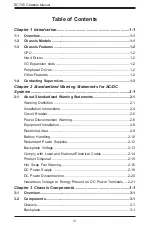
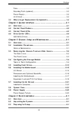
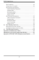
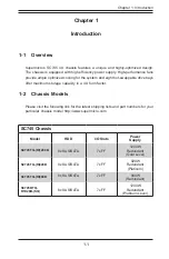
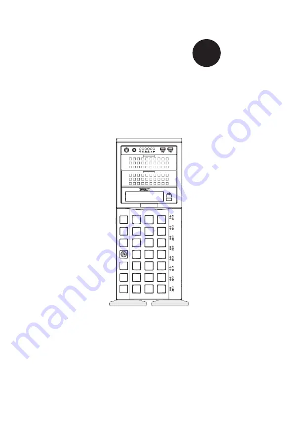
background image

SC745BTQ-R1K28B

SC745BTQ-R1K28B-SQ

SC745TQ-(R)1200B

SC745TQ-(R)920B

SC745TQ-(R)800B


USER’S MANUAL 

1.0b

SC745 CHASSIS

Series


S

UPER

®

Summary of Contents for SC745BTQ-R1K28B

Page 1: ...SC745BTQ R1K28B SC745BTQ R1K28B SQ SC745TQ R 1200B SC745TQ R 920B SC745TQ R 800B USER S MANUAL 1 0b SC745 CHASSIS Series SUPER...

Page 2: ...RDWARE SOFTWARE OR DATA STORED OR USED WITH THE PRODUCT INCLUDING THE COSTS OF REPAIRING REPLACING INTEGRATING INSTALLING OR RECOVERING SUCH HARDWARE SOFTWARE OR DATA Any disputes arising between manu...

Page 3: ...5 and up with the Platinum Level 1200W option and eight hot swappable 3 5 drive bays this chassis offers reliable performance with problem free maintenance Designed with 100 cooling redundancy via a c...

Page 4: ...s on this chassis model including the fans bays airflow shields and other components Chapter 4 System Interface Refer to this chapter for details on the system interface which includes the functions a...

Page 5: ...v Preface Appendix A Chassis Cables Appendix B Power Supply Specifications Appendix C SAS 743TQ Backplane Manual...

Page 6: ...tatements 2 1 Warning Definition 2 1 Installation Instructions 2 4 Circuit Breaker 2 5 Power Disconnection Warning 2 6 Equipment Installation 2 8 Restricted Area 2 9 Battery Handling 2 10 Redundant Po...

Page 7: ...1 5 3 Removing the Chassis Front and Side Covers 5 2 The Side Cover 5 2 The Front Cover 5 3 5 4 Configuring the Storage Module 5 4 Tower or Rack Configuration 5 4 5 5 Installing Hard Drives 5 13 5 6 I...

Page 8: ...erations 6 3 Ambient Operating Temperature 6 3 Reduced Airflow 6 3 Mechanical Loading 6 3 Circuit Overloading 6 3 Reliable Ground 6 3 6 4 Rack Mounting Instructions 6 4 Removing the Top Cover and Feet...

Page 9: ...e capacity in a 4U form factor 1 2 Chassis Models Please visit the following link for the latest shipping lists and part numbers for your particular chassis model http www supermicro com Chapter 1 Int...

Page 10: ...s can be removed without power ing down the server I O Expansion slots Each version of the SC745 chassis includes seven full I O expansion card PCI slots Peripheral Drives Each SC745 chassis provides...

Page 11: ...e Address Super Micro Computer B V Het Sterrenbeeld 28 5215 ML s Hertogenbosch The Netherlands Tel 31 0 73 6400390 Fax 31 0 73 6416525 Email sales supermicro nl General Information support supermicro...

Page 12: ...SC745 Chassis Manual 1 4 Notes...

Page 13: ...tment for assistance Only certified technicians should attempt to install or configure components Read this appendix in its entirety before installing or configuring components in the Supermicro chass...

Page 14: ...e los riesgos de la corriente el ctrica y familiar cese con los procedimientos est ndar de prevenci n de accidentes Al final de cada advertencia encontrar el n mero que le ayudar a encontrar el texto...

Page 15: ...l kan veroorzaken Voordat u aan enige apparatuur gaat werken dient u zich bewust te zijn van de bij een elektrische installatie betrokken risico s en dient u op de hoogte te zijn van de standaard proc...

Page 16: ...Systems an die Stromquelle die Installationsanweisungen lesen Advertencia Lea las instrucciones de instalaci n antes de conectar el sistema a la red de alimentaci n Attention Avant de brancher le sys...

Page 17: ...iert ist Stellen Sie sicher dass der Nennwert der Schutzvorrichtung nicht mehr als 60VDC 20A betr gt Advertencia Este equipo utiliza el sistema de protecci n contra cortocircuitos o sobrecorrientes de...

Page 18: ...Systemsbestandteile anzubringen oder zu entfernen Warning The system must be disconnected from all sources of power and the power cord removed from the power supply module s before accessing the chass...

Page 19: ...ponentes de sistema Attention Le syst me doit tre d branch de toutes les sources de puissance ainsi que de son cordon d alimentation secteur avant d acc der l int rieur du chassis pour installer ou en...

Page 20: ...s Installieren Ersetzen oder Bedienen dieser Ausr stung sollte nur geschultem qualifiziertem Personal gestattet werden Advertencia Solamente el personal calificado debe instalar reemplazar o utilizar...

Page 21: ...nstallation in Bereichen mit beschr nktem Zutritt vorgesehen Der Zutritt zu derartigen Bereichen ist nur mit einem Spezialwerkzeug Schloss und Schl ssel oder einer sonstigen Sicherheitsvorkehrung m gl...

Page 22: ...uivalent type recommended by the manufacturer Dispose of used batteries according to the manufacturer s instructions Waarschuwing Dit apparaat is bedoeld voor installatie in gebieden met een beperkte...

Page 23: ...recommand e par le fabricant Jeter les piles usag es conform ment aux instructions du fabricant Advertencia Existe peligro de explosi n si la bater a se reemplaza de manera incorrecta Reemplazar la b...

Page 24: ...ntes de alimentaci n Para cortar por completo el suministro de energ a deben desconectarse todas las conexiones Attention Cette unit peut avoir plus d une connexion d alimentation Pour supprimer toute...

Page 25: ...asero es peligroso Tenga cuidado cuando lo revise Attention Lorsque le syst me est en fonctionnement des tensions lectriques circulent sur le fond de panier Prendre des pr cautions lors de la maintena...

Page 26: ...codes Warnung Die Installation der Ger te muss den Sicherheitsstandards entsprechen Advertencia La instalacion del equipo debe cumplir con las normas de electricidad locales y nacionales Backplane Wa...

Page 27: ...tional laws and regulations Attention L quipement doit tre install conform ment aux normes lectriques nationales et locales Waarschuwing Bij installatie van de apparatuur moet worden voldaan aan de lo...

Page 28: ...odas las leyes y reglamentos nacionales Attention La mise au rebut ou le recyclage de ce produit sont g n ralement soumis des lois et ou directives de respect de l environnement Renseignez vous aupr s...

Page 29: ...os dedos los destornilladores y todos los objetos lejos de las aberturas del ventilador Attention Il est possible que les ventilateurs soient toujours en rotation lorsque vous retirerez le bloc ventil...

Page 30: ...sse z B f r einen geschlossenen Regelkreis oder gabelf rmig mit nach oben gerichteten Kabelschuhen zu verwenden Diese Abschl sse sollten die angemessene Gr e f r die Dr hte haben und sowohl die Isoli...

Page 31: ...de la taille qui convient aux fils et doivent tre referm es sur la gaine isolante et sur le conducteur Waarschuwing Wanneer geslagen bedrading vereist is dient u bedrading te gebruiken die voorzien i...

Page 32: ...ung der folgenden Vorg nge ist sicherzustellen da die Gleichstromschaltung keinen Strom erh lt Advertencia Antes de proceder con los siguientes pasos comprobar que la alimentaci n del circuito de corr...

Page 33: ...latie als de geleider vast te klemmen Hazardous voltage or energy may be present on DC power terminals Always replace cover when terminals are not in service Be sure uninsulated conductors are not acc...

Page 34: ...rique des terminaux courant continu peuvent tre dangereux Veillez toujours replacer le couvercle lors les terminaux ne sont pas en service Assurez vous que les conducteurs non isol s ne sont pas acces...

Page 35: ...chassis may include the following three options Eight hot swappable 3 5 hard drives Up to three double width GPUs Seven expansion slots For the latest shipping lists visit our website at www supermic...

Page 36: ...options rated at 800 920 1200 and 1280 Watts In the unlikely event your power supply fails replacement is simple and can be done without tools Air Shroud Air shrouds are shields usually plastic that f...

Page 37: ...ers to keep you constantly informed of the overall status of the system as well as the activity and health of specific components Most SC745 models have two buttons on the control panel a reset button...

Page 38: ...el is located on the front of the SC745 chassis and has five LEDs These LEDs provide you with critical information related to different parts of the system This section explains what each LED indicate...

Page 39: ...AN2 when flashing NIC1 Indicates network activity on GLAN1 when flashing HDD Indicates SAS SATA drive activity when flashing Power Indicates power is being supplied to the system s power supply units...

Page 40: ...a green LED When illuminated this green LED on the front of the SAS SATA drive carrier indicates drive activity A connection to the SATA backplane enables this LED to blink on and off when that parti...

Page 41: ...iguring the Storage Module Installing Hard Drives Installing the Motherboard Installing the Air Shroud and Checking the Airflow General Maintenance General Maintenance Systems Fans General Maintenance...

Page 42: ...the system and remove the power cords from the rear of the power supplies 2 Push the cover latch button to release the latch handle 3 Pull the cover off the chassis using the latch handle Replacing t...

Page 43: ...drives The cover can be locked to prevent unauthorized access The key to this lock is shipped with the system Removing the Front Cover 1 Unlock the front cover using the key shipped with the system 2...

Page 44: ...ion The SC745 chassis is shipped in tower mode and can be immediately used as desktop server If the chassis is to be used in a rack you must turn the storage module ninety degrees This should be done...

Page 45: ...dule and disconnect any cables from the storage mod ule to any component in the chassis 3 Push the storage module release lever This lever unlocks the storage mod ule 4 Grasp the external edges of the...

Page 46: ...one of three ways A Add up to three extra hard drives to the drive trays B Add up to three peripheral drives CD ROM DVD ROM etc drive trays C Add five hot swappable hard drives to the storage module...

Page 47: ...Trays 1 Power down the system and remove the power cords from the rear of the power supplies Open the chassis cover as described in Section 5 3 2 Locate the drive tray release tab for the slot in whic...

Page 48: ...ported by the motherboard 5 Secure the hard drive to the peripheral drive tray with four screws from the bottom 6 Slide the peripheral drive tray into the chassis until the tray clicks into place 7 Re...

Page 49: ...Adding up to Three Peripheral Drives to the Drive Trays 1 Power down the system and remove the power cords from the rear of the power supplies Open the chassis cover as described in Section 5 3 2 Loc...

Page 50: ...Attach the rails to a DVD ROM CD ROM or other peripherals The rails should fit any standard sized peripherals 6 Slide the peripheral drive tray into the chassis until the it clicks into place 7 Repeat...

Page 51: ...ile racks visit the Supermicro Web site at www supermicro com Adding Five Hard Drives Using A Supermicro Mobile Rack 1 Power down the system and remove the power cords from the rear of the power suppl...

Page 52: ...5 Attach the rails to the mobile rack Peripheral Tray Rails Peripheral Drive Tray Figure 5 12 Remove the Peripheral Tray Rails Figure 5 13 Add Peripheral Tray Rails to Storage Rack 6 Install all six h...

Page 53: ...roper airflow for the drive bays Installing Hard Drives to the Chassis 1 Unlock and open the chassis cover 2 Press the release button to extend the drive tray handle 3 Using the handle pull the drive...

Page 54: ...using the following steps 7a Press the hard drive release button to extend the drive tray handle 7b Insert the hard drive into the chassis and close the handle to lock the hard drive into place Figure...

Page 55: ...on Installing the I O Shield 1 Review the documentation that came with your motherboard Become familiar with component placement requirements and precautions 2 Power down the system and remove the pow...

Page 56: ...securing space between the motherboard and the chassis surface The SC745 chassis packaging includes optional standoffs hexagonal shaped posts These standoffs accept the rounded Phillips head screws wh...

Page 57: ...a flat surface 3 Open the chassis cover 4 As required by your motherboard install standoffs in any areas that do not have a permanent standoff 5 Lay the motherboard on the chassis aligning the perman...

Page 58: ...nge green and blue wires Hard drive power cable 2 backplane Each cable has three connectors two hard drive connectors and one floppy drive FDD connector Attach the HDD connectors to the back plane If...

Page 59: ...ystem and remove the power cords from the rear of the power supplies Open the chassis cover as described in Section 5 3 2 Locate the release tab on the top of the PCI slot bracket 3 Gently apply press...

Page 60: ...h erboard To do this slide the PCI card with L bracket into the PCI slot and secure the card to the motherboard 7 Push the PCI bracket release tab down until it locks into place with an audible click...

Page 61: ...d if motherboard compo nents prevent the air shroud from fitting securely Remove tabs only if necessary Installing the Air Shroud 1 Power down the system and remove the power cords from the rear of th...

Page 62: ...ough the chas sis Pull all excess cabling out of the airflow path or use shorter cables 4 The control panel LEDs inform you of system status See Chapter 3 System Interface for details on the LEDs and...

Page 63: ...ing a System Fan 1 Open the chassis cover and determine which fan has failed Because the fans are hot swappable the chassis does not have to be powered down 2 Press the fan release tab and lift the fa...

Page 64: ...gure 5 24 Rear Chassis Fans Replacing a Rear Chassis Fan 1 Press the rear fan release tab 2 Pull the fan from the chassis top first 3 Place the new fan in the chassis bottom first 4 Push the fan fully...

Page 65: ...tem automatically switches to the second power supply when the first fails If your system has only one power supply the system shuts down in the unlikely event of a power failure 5 9 Power Supply Repl...

Page 66: ...SC745 Chassis Manual 5 26 Notes...

Page 67: ...reas where heat electrical noise and electromagnetic fields are generated You will also need it placed near a grounded power outlet Be sure to read the Rack and Server Pre cautions in the next section...

Page 68: ...me unstable General Server Precautions Review the electrical and general safety precautions that came with the com ponents you are adding to your chassis Determine the placement of each component in t...

Page 69: ...e consideration should be given to installing the equipment in an environment compatible with the manufacturer s maximum rated ambient temperature TMRA Reduced Airflow Equipment should be mounted into...

Page 70: ...e will differ slightly You should also refer to the instal lation instructions that came with the rack unit you are using NOTE The outer rail is adjustable from 26 to 35 9 Removing the Top Cover and F...

Page 71: ...over off the chassis Removing the Chassis Feet 1 Power down the system and remove the power cords from the rear of the power supplies Open the chassis cover as described in Section 5 3 2 Place the cha...

Page 72: ...e Rack Rails The chassis package includes two rack rail assemblies in the rack mounting kit Each assembly consists of two sections an inner fixed chassis rail that secures directly to the server chass...

Page 73: ...th the front of the chassis and secure with the three chassis handle screws 3 Repeats steps 1 and 2 with the other handle 4 Locate the two inner rails and twelve screws in the shipping package 5 Align...

Page 74: ...to the proper distance so that the rail fits snugly into the rack 3 Secure the front side of the outer rail with two M5 screws and the rear side of the outer rail with three M5 screws NOTE The outer...

Page 75: ...you should hear the locking tabs click Fro m To Subject Siz e Rec eived Ro d Coleman Ray mond Miller RE SC825 C hassis User M anual 4 KB F Stability hazard The rack stabilizing mechanism must be in p...

Page 76: ...over 1 Power down the system and remove the power cords from the rear of the power supplies Open the chassis cover as described in Section 5 3 2 Remove the rack mount ears 3 Align the cover post with...

Page 77: ...le and slide the foot toward the front of the chassis The foot should lock into place 2 Secure the foot to the chassis using one screw enclosed in the packaging 3 Repeat steps 1 and 2 for the remainin...

Page 78: ...SC745 Chassis Manual 6 12 Notes...

Page 79: ...the motherboard you are using and our Web site at www supermicro com A 2 Cables Included with SC745TQ Chassis SAS SATA Part Type Length Description CBL 0157L Cable 40 cm 8 pin to 8 pin ribbon cable fo...

Page 80: ...at the SAS SATA cables must share use the following cable This cable must be purchased separately Description This cable has one iPass SFF 8087 Mini SAS connector 36 pin at one end and four SAS SATA c...

Page 81: ...to extend the power cables to the mother boards To do this use the following chart as a guide Power Cable Extenders Number of Pins Cable Part Length 24 pin CBL 0042L 7 9 20 cm 20 pin CBL 0059L 7 9 20...

Page 82: ...SC745 Chassis Manual A 4 Notes...

Page 83: ...r your chassis system 800W Redundant X2 MFR Part PWS 801 1R Rated AC Voltage 100 240V 50 60Hz 10 4 Amp 5V standby 4 Amp 12V 66 Amp 5V 30 Amp 3 3V 24 Amp 12V 0 6 Amp 920W Redundant X2 MFR Part PWS 920P...

Page 84: ...40V 50 60Hz 5 5 8 Amp DC Output 12V 1000W 83 Amp 100 140V 1200W 100 Amp 180 240V 5Vsb 4A DC Output with PDB 5V 50 Amp 3 3V 30 Amp 12V 0 6 Amp 1280W Redundant MFR Part PWS 1K28P SQ AC Input 1000W Outpu...

Page 85: ...ed to prevent static discharge Touch a grounded metal object before removing a component from the antistatic bag Handle the backplane by its edges only do not touch its components peripheral chips mem...

Page 86: ...shown in this manual C 4 Introduction to the SAS 743TQ Backplane The SAS 743TQ backplane has been designed to utilize the most up to date tech nology available providing your system with reliable hig...

Page 87: ...ors 4 pin JP10 and JP13 5 ACT IN JP26 6 Sideband Connector 2 JP52 7 Sideband Connector 1 JP51 8 I2 C Connector 2 JP45 9 I2 C Connector 1 JP44 10 SAS Port 0 J5 11 SAS Port 1 J6 12 SAS Port 2 J7 13 SAS...

Page 88: ...072 is an enclosure management chip that supports the SES 2 controller and SES 2 protocols Backplane Main Power 4 Pin Connector Pin Definition 1 12V 2 and 3 Ground 4 5V 4 Backplane Main Power Connecto...

Page 89: ...4 3 GND SB2 6 GND SB3 5 SDA SB1 8 Backplane ID SB7 7 SCL SB0 10 No Connec tion 9 No Connec tion 8 and 9 I2 C Connectors The I2 C Connectors designated JP44 and JP45 are used to monitor HDD activity an...

Page 90: ...C 6 SC745 Chassis Manual 2 3 Front Jumper Locations and Pin Definitions JP50 JP29 JP18 JP42 JP43 JP40 JP33 JP36 JP38 JP41 JP34 JP37 Figure C 2 Front Jumpers...

Page 91: ...d circuit board Note On two pin jumpers Closed means the jumper is on and Open means the jumper is off the pins Connector Pins Jumper Setting 3 2 1 3 2 1 Jumper Settings Jumper Jumper Settings Note JP...

Page 92: ...0 Pins 1 2 Backplane ID 1 JP36 Pins 2 3 Pins 1 2 Controller ID 2 JP37 Pins 2 3 ID 1 Pins 1 2 Backplane ID 2 JP38 Closed Open I2 C Reset 2 JP40 Open Closed I2 C Reset SDOUT 1 JP41 Open Closed I2 C Rese...

Page 93: ...AS 743TQ Backplane Specifications Front Panel LEDs LED State Specification D3 On Overheat drive failure LED indicator Red light flashing Buzzer On if activated Front LED Indicators OH Drive Fail LED F...

Page 94: ...4 SAS SATA HHD 4 SAS 5 SAS SATA HHD 5 SAS 6 SAS SATA HHD 6 SAS 7 SAS SATA HHD 7 Rear LED Indicators Rear LED Hard Drive Activity Failure LED SAS 0 D12 D5 SAS 1 D13 D6 SAS 2 D14 D7 SAS 3 D15 D8 SAS 4 D...

Page 95: ...C 11 Appendix C BPN SAS 743TQ Backplane Specifications Notes...

Page 96: ...reasonably expected to result in significant injury or loss of life or catastrophic property damage Accordingly Supermicro disclaims any and all liability and should buyer use or sell such products fo...

Reviews: