background image

SC812L CHASSIS SERIES

S

UPER

USER’S MANUAL

1.0

SC812L-520U

SC812L-280U

SC812L-520

SC812L-420

SC812L-520C

SC812L-420C

SC812L-410

SC812L-U

SC812L

Summary of Contents for SC812L-280U

Page 1: ...SC812L CHASSIS SERIES SUPER USER S MANUAL 1 0 SC812L 520U SC812L 280U SC812L 520 SC812L 420 SC812L 520C SC812L 420C SC812L 410 SC812L U SC812L ...

Page 2: ...ITY TO USE THIS PRODUCT OR DOCUMENTATION EVEN IF ADVISED OF THE POSSIBILITY OF SUCH DAMAGES IN PARTICULAR THE VENDOR SHALL NOT HAVE LIABILITY FOR ANY HARDWARE SOFTWARE OR DATA STORED OR USED WITH THE PRODUCT INCLUDING THE COSTS OF REPAIRING REPLACING INTEGRATING INSTALLING OR RECOVERING SUCH HARDWARE SOFTWARE OR DATA Any disputes arising between manufacturer and customer shall be governed by the l...

Page 3: ...perienced technicians only Supermicro s SC812L 1U chassis features a unique and highly optimized design for dual core Xeon platforms The chassis is equipped with a high efficiency power supply for superb power savings High performance cooling blowers provide ample optimized cooling This document lists compatible parts available when this document was published Always refer to the our Web site for ...

Page 4: ...SC812L Chassis Manual iv Notes ...

Page 5: ...omponents Refer here for details on this chassis model including the fans bays airflow shields and other components Chapter 4 System Interface Refer to this chapter for details on the system interface which includes the functions and information provided by the control panel on the chassis as well as other LEDs located throughout the system Chapter 5 Chassis Setup and Installation Follow the proce...

Page 6: ...Backplanes This section lists compatible cables power supply specifications and compatible backplanes Not all compatible backplanes are listed Refer to our Web site for the latest compatible backplane information Appendix A Chassis Cables ...

Page 7: ...autions 2 2 2 6 System Safety 2 3 Chapter 3 System Interface 3 1 Overview 3 1 3 2 Control Panel Buttons 3 2 3 3 Control Panel LEDs 3 2 Chapter 4 Chassis Setup and Maintenance 4 1 Overview 4 1 4 2 Installation Steps 4 1 4 3 Installation Step 1 Remove the Chassis Cover 4 2 To remove the chassis cover 4 2 4 4 Installation Step 2 Install Hard Drives 4 3 To install a hard drive to the chassis 4 3 4 5 I...

Page 8: ... a Setup Location 5 1 Rack Precautions 5 2 General Server Precautions 5 2 Rack Mounting Considerations 5 2 Ambient Operating Temperature 5 2 Reduced Airflow 5 3 Mechanical Loading 5 3 Circuit Overloading 5 3 Reliable Ground 5 3 5 4 Rack Mounting Instructions 5 4 Identifying the Sections of the Rack Rails 5 4 To remove the fixed chassis rail 5 4 To install the inner rail to the chassis 5 5 To insta...

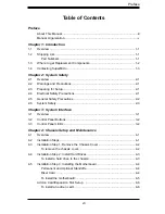
Page 9: ...ix Preface Front Panel to the Motherboard A 3 A 4 Chassis Screws A 4 ...

Page 10: ...SC812L Chassis Manual x Notes ...

Page 11: ...d part numbers for your particular chassis model http www supermicro com Chapter 1 Introduction 1 1 SC812L Chassis Model CPU HDD I O Slots Power Supply SC812L 420 DP Dual core Xeon 3 Fixed Hard Drives 1x FF 1x LP 420W SC812L 420C DP Dual core Xeon 3 Fixed Hard Drives 1x FF 420W SC812L 410 DP Dual core Xeon 3 Fixed Hard Drives 1x FF 1x LP 410W SC812L 520 DP Dual core Xeon 3 Fixed Hard Drives 1x FF ...

Page 12: ... To en sure the highest level of professional service and technical support we strongly recommend purchasing exclusively from our Supermicro Authorized Distributors System Integrators Resellers A list of Supermicro Authorized Distributors Sys tem Integrators Reseller can be found at http www supermicro com Click the Where to Buy link ...

Page 13: ...ss SuperMicro Computer B V Het Sterrenbeeld 28 5215 ML s Hertogenbosch The Netherlands Tel 31 0 73 6400390 Fax 31 0 73 6416525 Email sales supermicro nl General Information support supermicro nl Technical Support rma supermicro nl Customer Support Asia Pacific Address SuperMicro Taiwan 4F No 232 1 Liancheng Rd Chung Ho 235 Taipei County Taiwan R O C Tel 886 2 8226 3990 Fax 886 2 8226 3991 Web Site...

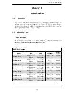
Page 14: ...SC812L Chassis Manual 1 4 Notes ...

Page 15: ...is It should be situated in a clean dust free area that is well ventilated Avoid areas where heat electrical noise and electromagnetic fields are generated You will also need it placed near at least one grounded power outlet 2 3 Preparing for Setup The SC812L Chassis includes a set of rail assemblies including mounting brackets and mounting screws you will need to install the systems into the rack...

Page 16: ... which can easily damage any electrical components or circuit boards they come into contact with l Do not use mats designed to decrease electrostatic discharge as protection from electrical shock Instead use rubber mats that have been specifically designed as electrical insulators l The power supply power cord must include a grounding plug and must be plugged into grounded electrical outlets l Ser...

Page 17: ...ted by two objects with different electrical charges coming into contact with each other An electrical discharge is created to neutralize this difference which can damage electronic components and printed circuit boards The following measures are generally sufficient to neutralize this difference before contact is made to protect your equipment from ESD l Do not use mats designed to decrease elect...

Page 18: ...ching their pins l Put the serverboard and peripherals back into their antistatic bags when not in use l For grounding purposes make sure your computer chassis provides excel lent conductivity between the power supply the case the mounting fasten ers and the serverboard ...

Page 19: ...s others on the drive carriers to keep you constantly informed of the overall status of the system as well as the activity and health of specific components This chapter explains the meanings of all LED indicators and the appropriate response you may need to take Figure 3 2 SC812L Front Panel Figure 3 1 SC812L U Front Panel ...

Page 20: ...the SC812L chassis has five LEDs These LEDs provide you with critical information related to different parts of the system This section explains what each LED indicates when illuminated and any corrective action you may need to take l Overheat Fan Fail When this LED flashes it indicates a fan failure When continuously on not flashing it indicates an overheat condition which may be caused by cables...

Page 21: ...icates network activity on GLAN1 when flashing l HDD Indicates IDE channel activity SAS SATA drive SCSI drive and or DVD ROM drive activity when flashing l Power Indicates power is being supplied to the system s power supply units This LED should normally be illuminated when the system is operating ...

Page 22: ...SC812L Chassis Manual 3 4 Notes ...

Page 23: ...ting up your chassis 4 2 Installation Steps 4 3 Installation Step 1 Remove the Chassis Cover 4 2 4 4 Installation Step 2 Install Hard Drives 4 3 4 5 Installation Step 3 Installing the Motherboard 4 4 4 6 Installation Step 4 System Blowers 4 8 4 7 Installation Step 5 Installing the Air Shroud 4 10 4 8 Installation Complete 4 11 Review the warnings and precautions listed in the manual be fore settin...

Page 24: ... at the same time 2 Once the top cover is released from the locked position slide the cover toward the rear of the chassis 3 Lift the cover off the chassis Warning Except for short periods of time do NOT operate the server without the cover in place The chassis cover must be in place to allow proper airflow and prevent overheating Figure 4 1 Removing the Chassis Cover 1 2 1 3 Release Tab ...

Page 25: ...hassis 3 Connect a standard hard drive to the bracket and secure the connection with the four screws connected to the bracket NOTE The bracket includes four screws and four rubber feet Always use the rubber feet with installing the hard drive 4 Carefully slide replace the bracket in the chassis and secure the hard drive with the screw that was previously removed Figure 4 2 Remove the Hard Drive Ha...

Page 26: ...re additional screws for heatsinks general components and or non standard security Optional standoffs are included to these mother boards To use an optional standoff you must place the hexagonal screw through the bottom the chassis and secure the screw with the hexagon nut rounded side up Riser Card SC812L chassis include permanent riser cards that allow the chassis to utilize a variety of add on ...

Page 27: ... Secure the screw with the hexagon nut rounded side up 5 Lay the motherboard on the chassis aligning the permanent and optional standoffs 6 Secure the motherboard to the chassis using the rounded Phillips head screws 7 Secure the CPU s heatsinks and other components to the motherboard as described in the motherboard documentation 8 Connect the cables between the motherboard backplane chassis front...

Page 28: ...d on card slots and one low profile slot Figure 4 5 SC812L Add on Card To install an add on card 1 Disconnect the power supply lay the chassis on a flat surface and open the chassis cover 2 In the rear of the chassis pull open the add on card clip and remove the add on card shield 3 If you have not already done so remove the Riser Card Bracket To do so simple remove the screws and life the Riser C...

Page 29: ...ard embedded in the riser card bracket 5 Re connect the riser card with add on cards to the motherboard 6 Secure each card to the chassis using the card s L bracket and close the add on card shield clip 7 Some SC812L U models may require the add on card be secured to the chassis with screw If so secure the add on card at this time 8 Replace the chassis cover and continue setup according to the add...

Page 30: ...lower rack for the SC812L can be adjusted into two different positions Left and Right The blower rack for the SC812L U series chassis can be configured in up to four positions The only positions needed are the two positions furthest to the right Blowers can be removed from the blower rack and rotated by 15 degrees The chassis includes foam barriers that regulate the air stream to the rear of the c...

Page 31: ...dary Position The following only applies to non U brand chassis When using a SuperMicro motherboard with an AMD CPU do the following 1 Disconnect the blowers from the motherboard and remove the foam barrier from the chassis 2 Move the rack one position to the left 3 Remove the right blower and turn it so that it points directly toward the rear of the chassis 4 Confirm that the first blower is also...

Page 32: ... behind the two blowers closest to the power supply To check the server air flow 1 Make sure there are no objects to obstruct airflow in and out of the server In addition if you are using a front bezel make sure the bezel s filter is replaced periodically 2 Do not operate the server without drives or drive trays in the drive bays Use only recommended server parts 3 Make sure no wires or foreign ob...

Page 33: ...ete In most cases the chassis power supply and blowers are pre installed If you need to install blowers continue to the Systems Blower section of this chapter If the chassis will be installed into a rack continue to the next chapter for rack installa tion instructions ...

Page 34: ...hange the power supply 1 Power down the server and unplug the power cord 2 Remove power cord from the rear of the chassis and disconnect the power supply for the motherboard and other chassis components 3 In the front the power supply is held to the chassis by two L brackets Re move the two screws that secure the L bracket to the chassis 4 In the rear the power supply is secured by two screws 5 Li...

Page 35: ...t placed near a grounded power outlet Be sure to read the Rack and Server Precautions in the next section 5 3 Preparing for Setup The box your chassis was shipped in should include two sets of rail assemblies two rail mounting brackets and the mounting screws you will need to install the system into the rack Please read this section in its entirety before you begin the installation procedure outli...

Page 36: ...ver components on the bottom of the rack first and then work up Use a regulating uninterruptible power supply UPS to protect the server from power surges voltage spikes and to keep your system operating in case of a power failure Allow the hot plug hard drives and power supply modules to cool before touch ing them Always keep the rack s front door and all panels and components on the servers close...

Page 37: ... supply circuitry and the effect that any possible overloading of circuits might have on overcurrent protection and power supply wiring Appropriate consideration of equipment nameplate ratings should be used when addressing this concern Reliable Ground A reliable ground must be maintained at all times To ensure this the rack itself should be grounded Particular attention should be given to power s...

Page 38: ...ng NOTE The rails will fit a rack between 29 and 35 25 deep Identifying the Sections of the Rails The chassis package includes two rail assemblies in the rack mounting kit Each assembly consists of two sections an inner fixed chassis rail that secures directly to the server chassis and an outer rack rail that secures directly to the rack itself Rail Brackets The chassis package includes four rail ...

Page 39: ... six M5 flat head screws 3 Repeat steps 1 and 2 for the other chassis Figure 5 2 Rail Installation Inner Chassis Rail Figure 5 1 Inner and Outer Rails A B C To separate the inner and outer rails 1 Pull the inner rail A from the outer rail B as far as possible 2 Depress the locking tab C to pull the inner rail completely out 3 Repeat steps 1 and 2 for the other rail ...

Page 40: ...rt brackets to the front of the outer rails with two M4 screws 4 Secure the long brackets to the outer rails using two M4 screws Tighten the screws loosely so the bracket can slide back and forth 5 Position the outer rail and brackets in the rack at the desired level 6 Secure the front of the rail to the rack using two M5 rack screws 7 Slide the rear bracket so that it snugly fits into the rack Se...

Page 41: ...5 7 Chapter 5 Rack Installation Figure 5 3 Mounting the Chassis A B Rail Bracket C ...

Page 42: ...gn the chassis rails A with the front of the rack rails C 3 Slide the chassis rails into the rack rails keeping the pressure even on both sides you may have to depress the locking tabs when inserting When the server has been pushed completely into the rack you should hear the locking tabs click 4 Optional Insert and tightening the thumbscrews that hold the front of the server to the rack ...

Page 43: ...nstallation You must reverse the brackets to accommodate two posts instead of four 1 Install the inner rails to the chassis as described in this chapter 2 Attach the short and long brackets to the outer rails as illustrated For the short brackets use one M4 screw placed in the oval screw mount For the long brackets use the two M4 screws placed in the two middle oval screw mounts Tighten the screws...

Page 44: ...crews for each bracket 8 Tighten the M4 screws that secure each bracket to the outer rail 9 Repeat steps 5 9 using the second outer rail 10 Line the inner chassis rails A with the front of the outer rails C see Figure 5 3 11 Slide the chassis rails into the rack rails keeping the pressure even on both sides you may have to depress the locking tabs when inserting When the server has been pushed com...

Page 45: ...ck Installation 12 Optional If you installed the front chassis mount you can insert thumb screws through the chassis ears and chassis mounts The chassis cannot be pulled from the rack unless the thumbscrews are removed ...

Page 46: ...SC812L Chassis Manual 5 12 Notes ...

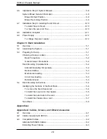
Page 47: ...1 Appendices Appendices Appendix A Compatible Cables ...

Page 48: ...SC812L Chassis Manual 2 Notes ...

Page 49: ... components and configurations For more compatible cables refer to the manufacturer of the motherboard you are using and our Web site at www supermicro com A 2 Cables Included with SC812L Part Type Length Description CBL 036 Cable various IDE ATA100 66 3 DROPS CABLE W LOW PROFILE CONNECTORS CBL 0087 Ribbon Round 20 16 pin to 16 pin ribbon cable for control panel Cable 6 Regional power cord ...

Page 50: ...ternate SAS SATA Cables Some compatible motherboards may have different connectors If your motherboard has only one SAS connector that the SAS SATA cables must share use one of the following cables These cables must be purchased separately Description This cable has one ipass SFF 8087 mini sas connector 36 pins at one end and 4 SAS connectors on one end This cable connects from the Host motherboar...

Page 51: ...0 pin CBL 0059 7 9 20 CM 8 pin CBL 0062 7 9 20 CM 4 pin CBL 0060 7 9 20 CM Front Panel to the Motherboard The SC812L chassis includes a cable to connect the chassis front panel to the motherboard If your motherboard uses a different connector use the following list to find a compatible cable Front Panel to Motherboard Cable Ribbon Cable Number of Pins Front Panel Number of Pins Motherboard Cable P...

Page 52: ...Flat head M4 x 4 mm 0 157 RAIL Round head M4 x 4 mm 0 157 Flat head M5 x 12 mm 0 472 Washer for M5 DVD ROM CD ROM and FLOPPY DRIVE Flat head 6 32 x 5 mm 0 197 Pan head 6 32 x 5 mm 0 197 Round head M3 x 5 mm 0 197 Pan head 6 32 x 5 mm 0 197 M B Flat head 6 32 x 5 mm 0 197 HARD DRIVE Thumb screw 6 32 x 5 mm 0 197 M B standoff 6 32 to 6 32 M B STANDOFFS M B CPU standoff M5 to 6 32 Round head M2 6 x 5...

Reviews: