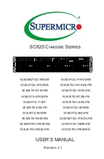
background image

USER’S MANUAL

Revision 2.1

SC825 Chassis Series

SC825B2TQC-R920W

SC825TQC-R1K03WB

SC825TQC-R740WB

SC825TQC-R1K03LPB

SC825TQ-R740WB

SC825TQC-R740LPB

SC825TQ-R740LPB

SC825TQ-R720LPB

SC825TQ-710LP

SC825TQC-600LPB

SC825TQ-600LPB

SC825TQC-600WB

SC835TQ-600WB

SC825TQ-563LPB

SC825TQ-R500WB

SC825BTQC-R1K23LPB

SC825BTQC-R609WB

SC825TQC-R609LPB

SC825TQC-R802LPB

SC825TQC-R802WB

~

Summary of Contents for SC825 Series

Page 1: ...825TQC R740WB SC825TQC R1K03LPB SC825TQ R740WB SC825TQC R740LPB SC825TQ R740LPB SC825TQ R720LPB SC825TQ 710LP SC825TQC 600LPB SC825TQ 600LPB SC825TQC 600WB SC835TQ 600WB SC825TQ 563LPB SC825TQ R500WB SC825BTQC R1K23LPB SC825BTQC R609WB SC825TQC R609LPB SC825TQC R802LPB SC825TQC R802WB ...

Page 2: ...f any such disputes Super Micro s total liability for all claims will not exceed the price paid for the hardware product FCC Statement This equipment has been tested and found to comply with the limits for a Class A digital device pursuant to Part 15 of the FCC Rules These limits are designed to provide reasonable protection against harmful interference when the equipment is operated in a commerci...

Page 3: ...ailable when this document was published Refer to the Supermicro web site for updates on supported parts and configurations This manual may be periodically updated without notice Please check the Supermicro Web site for possible updates Warnings Special attention should be given to the following symbols used in this manual Warning Indicates high voltage may be encountered when performing a procedu...

Page 4: ...ndardized Warning Statements 2 1 Warning Definition 2 1 Installation Instructions 2 4 Circuit Breaker 2 5 Power Disconnection Warning 2 6 Equipment Installation 2 8 Restricted Area 2 9 Battery Handling 2 10 Redundant Power Supplies 2 12 Backplane Voltage 2 13 Comply with Local and National Electrical Codes 2 14 Product Disposal 2 15 Power Cable and AC Adapter 2 18 Chapter 3 Chassis Components 3 1 ...

Page 5: ...g the Rear Drives into Carriers CSE 825B Only 5 10 5 7 DVD ROM Replacement or Installation 5 11 Replacing the DVD ROM and Front Panel 5 11 5 8 Installing the Motherboard 5 12 I O Shield 5 12 Installing the I O Shield SC825 LP model only 5 12 Permanent and Optional Standoffs 5 13 Expansion Card PCI Slot Setup 5 15 PCI Slot Setup in LP Low Profile Chassis 5 15 PCI Slot Setup for SC825U Universal Out...

Page 6: ...ed Airflow 6 3 Mechanical Loading 6 3 Circuit Overloading 6 3 Reliable Ground 6 3 6 4 Installing the System into a Rack 6 4 Identifying the Sections of the Rack Rails 6 4 Releasing the Inner Rail 6 5 Installing the Inner Rails on the Chassis 6 6 Installing the Outer Rails onto the Rack 6 7 Sliding the Chassis onto the Rack Rails 6 8 Appendix A SC825 Power Supply Specifications A 1 Appendix B BPN S...

Page 7: ...Super Micro Computer B V Het Sterrenbeeld 28 5215 ML s Hertogenbosch The Netherlands Tel 31 0 73 6400390 Fax 31 0 73 6416525 Email sales supermicro nl General Information support supermicro nl Technical Support rma supermicro nl Customer Support Web Site www supermicro nl Asia Pacific Address Super Micro Computer Inc 3F No 150 Jian 1st Rd Zhonghe Dist New Taipei City 235 Taiwan R O C Tel 886 2 822...

Page 8: ...8 SC825 Chassis Manual Notes ...

Page 9: ...SATA 4x FH 3x LP 740W Platinum Level Redundant SC825TQC R740WB 8x SAS3 SATA 4x FH 3x LP 740W Platinum Level Redundant SC825TQC R740LPB 8x SAS3 SATA 7x LP 740W Platinum Level Redundant SC825TQ R740LPB 8x SAS SATA 7x LP 740W Platinum Level Redundant SC825TQ 720LPB 8x SAS SATA 7x LP 720W Gold Level SC825TQ 710LPB 8x SAS SATA 7x LP 710W SC825TQC 600LPB 8x SAS3 SATA 7x LP 600W Platinum Level SC825TQC 6...

Page 10: ...dant SC825TQC R609LPB 8x SAS SATA 7x LP 600W 650W Platinum Level Redundant SC825TQC R802LPB 8x SAS SATA 7x LP 800W Titanium Level Redundant SC825TQC R802WB 8x SAS SATA 4x FH 3x LP 800W Titanium Level Redundant Legend FF Full height full length FH Full height half length LF Low profile full length LP Low profile ...

Page 11: ...l 2 5 hot swap drive kit MCP 220 82616 0N PCI Expansion slots Each SC825 LP chassis model includes seven low profile I O expansion slots SC825 W supports four FH and three low profile I O expansion slots Peripheral Drives Each SC825 chassis supports one slim DVD ROM drive and one slim USB com port drive slot optional These drives allow you to quickly install or save data Other Features Other onboa...

Page 12: ...e Address Super Micro Computer B V Het Sterrenbeeld 28 5215 ML s Hertogenbosch The Netherlands Tel 31 0 73 6400390 Fax 31 0 73 6416525 Email sales supermicro nl General Information support supermicro nl Technical Support rma supermicro nl Customer Support Website www supermicro nl Asia Pacific Address Super Micro Computer Inc 3F No 150 Jian 1st Rd Zhonghe Dist New Taipei City 235 Taiwan R O C Tel ...

Page 13: ...that must be mailed when service is complete For faster service RMA authorizations may be requested online http www super micro com support rma Whenever possible repack the chassis in the original Supermicro carton using the original packaging material If these are no longer available be sure to pack the chassis securely using packaging material to surround the chassis so that it does not shift wi...

Page 14: ...SC825 Chassis Manual 1 6 Notes ...

Page 15: ...r configuring components in the Supermicro chassis These warnings may also be found on our web site at http www supermicro com about policies safety_information cfm Warning Definition 警告の定義 この警告サインは危険を意味します 人身事故につながる可能性がありますので いずれの機器でも動作させる前に 電気回路に含まれる危険性に注意して 標準的な事故防止策に精通して下さい 此警告符号代表危险 您正处于可能受到严重伤害的工作环境中 在您使用设备开始工作之前 必须充分 意识到触电的危险 并熟练掌握防止事故发生的标准工作程序 请根据每项警告结 尾的声明号码找到此设备的安全性警告说明的翻译文本 此警告符號代表危險 您目...

Page 16: ...ero que le ayudará a encontrar el texto traducido en el apartado de traducciones que acompaña a este dispositivo GUARDE ESTAS INSTRUCCIONES IMPORTANTES INFORMATIONS DE SÉCURITÉ Ce symbole d avertissement indique un danger Vous vous trouvez dans une situation pouvant entraîner des blessures ou des dommages corporels Avant de travailler sur un équipement soyez conscient des dangers liés aux circuits...

Page 17: ...n enige apparatuur gaat werken dient u zich bewust te zijn van de bij een elektrische installatie betrokken risico s en dient u op de hoogte te zijn van de standaard procedures om ongelukken te voorkomen Gebruik de nummers aan het eind van elke waarschuwing om deze te herleiden naar de desbetreffende locatie BEWAAR DEZE INSTRUCTIES خطز ٌ ع الزهز هذا ٌ ة جسذ اصابة ف تتسبب أى يك ٌ و حالة ف ً ك ا ٌ ز...

Page 18: ...ystème sur la source d alimentation consulter les directives d installation 設置手順書 システムを電源に接続する前に 設置手順書をお読み下さい 시스템을 전원에 연결하기 전에 설치 안내를 읽어주십시오 Waarschuwing Raadpleeg de installatie instructies voordat u het systeem op de voedingsbron aansluit 警告 将此系统连接电源前 请先阅读安装说明 警告 將系統與電源連接前 請先閱讀安裝說明 Warning Read the installation instructions before connecting the system to the power source מתח למקור המערכת חיבור ...

Page 19: ...r ce qui est de la protection contre les courts circuits surtension ce produit dépend de l installation électrique du local Vérifiez que le courant nominal du dispositif de protection n est pas supérieur à 250 V 20 A 警告 此产品的短路 过载电流 保护由建筑物的供电系统提供 确保短路保护设备的额定电 流不大于250V 20A 警告 此產品的短路 過載電流 保護由建築物的供電系統提供 確保短路保護設備的額定電 流不大於250V 20A Warning This product relies on the building s installation for short circ...

Page 20: ...Spg Versorgungsteilmodulen entfernt wird bevor es 경고 이 제품은 전원의 단락 과전류 방지에 대해서 전적으로 건물의 관련 설비에 의존합니다 보호장치의 정격이 반드시 250V 볼트 20A 암페어 를 초과하지 않도록 해야 합니다 Waarschuwing Dit product is afhankelijk van de kortsluitbeveiliging overspanning van uw electrische installatie Controleer of het beveiligde aparaat niet groter gedimensioneerd is dan 220V 20A Warning The system must be disconnected from all sources of...

Page 21: ...céder à l intérieur du chassis pour installer ou enlever des composants de systéme 경고 시스템에 부품들을 장착하거나 제거하기 위해서는 섀시 내부에 접근하기 전에 반드시 전원 공급장치로부터 연결되어있는 모든 전원과 전기코드를 분리해주어야 합니다 Waarschuwing Voordat u toegang neemt tot het binnenwerk van de behuizing voor het installeren of verwijderen van systeem onderdelen dient u alle spanningsbronnen en alle stroomkabels aangesloten op de voeding en van de behuizin...

Page 22: ...ntion Il est vivement recommandé de confier l installation le remplacement et la maintenance de ces équipements à des personnels qualifiés et expérimentés 경고 훈련을 받고 공인된 기술자만이 이 장비의 설치 교체 또는 서비스를 수행할 수 있습니다 警告 只有经过培训且具有资格的人员才能进行此设备的安装 更换和维修 警告 只有經過受訓且具資格人員才可安裝 更換與維修此設備 Warning Only trained and qualified personnel should be allowed to install replace or service this equipment אזהרה לתת או הציוד את ל...

Page 23: ...instalación en áreas de acceso restringido Sólo puede obtenerse acceso a una de estas áreas mediante la utilización de una herramienta especial cerradura con llave u otro medio de seguridad Attention Cet appareil doit être installée dans des zones d accès réservés L accès à une zone d accès réservé n est possible qu en utilisant un outil spécial un mécanisme de verrouillage et une clé ou tout autr...

Page 24: ...使用済電池は製造元の指示に従 って処分して下さい 警告 电池更换不当会有爆炸危险 请只使用同类电池或制造商推荐的功能相当的电池更 换原有电池 请按制造商的说明处理废旧电池 警告 電池更換不當會有爆炸危險 請使用製造商建議之相同或功能相當的電池更換原有 電池 請按照製造商的說明指示處理廢棄舊電池 מוגבלת גישה עם אזור אזהרה הגישה גישה הגבלת בהם שיש באזורים היחידה את להתקין יש בעזרת ניתנת וכד מנעול מפתח בלבד אבטחה כלי تم محظورة مناطق ف ُها ب نترك انىحذة هذه تخصيص أداة استخذاو خالل من فقط محظورة منطقت إن انىصىل كن َ م خاصت ومفتاح قفم نالألمما أخري ...

Page 25: ...tipo o el equivalente recomendado por el fabricante Desechar las baterías gastadas según las instrucciones del fabricante 경고 배터리가 올바르게 교체되지 않으면 폭발의 위험이 있습니다 기존 배터리와 동일하거나 제조사에서 권장하는 동등한 종류의 배터리로만 교체해야 합니다 제조사의 안내에 따라 사용된 배터리를 처리하여 주십시오 Waarschuwing Er is ontploffingsgevaar indien de batterij verkeerd vervangen wordt Vervang de batterij slechts met hetzelfde of een equivalent type die door de fabri...

Page 26: ...ité peut avoir plus d une connexion d alimentation Pour supprimer toute tension et tout courant électrique de l unité toutes les connexions d alimentation doivent être débranchées Redundant Power Supplies 冗長電源装置 このユニッ トは複数の電源装置が接続されている場合があります ユニッ トの電源を切るためには すべての接続を取り外さなければなりません 警告 此部件连接的电源可能不止一个 必须将所有电源断开才能停止给该部件供电 警告 此裝置連接的電源可能不只一個 必須切斷所有電源才能停止對該裝置的供電 Warning This unit might have more than one p...

Page 27: ...dado cuando lo revise Attention Lorsque le système est en fonctionnement des tensions électriques circulent sur le fond de panier Prendre des précautions lors de la maintenance 경고 이 장치에는 한 개 이상의 전원 공급 단자가 연결되어 있을 수 있습니다 이 장치에 전원을 차단하기 위해서는 모든 연결 단자를 제거해야만 합니다 Waarschuwing Deze eenheid kan meer dan één stroomtoevoeraansluiting bevatten Alle aansluitingen dienen verwijderd te worden om het apparaat ...

Page 28: ... 에는 위험한 전압이나 에너지가 발생 합니다 서비스 작업 시 주의하십시오 Waarschuwing Een gevaarlijke spanning of energie is aanwezig op de backplane wanneer het systeem in gebruik is Voorzichtigheid is geboden tijdens het onderhoud 警告 设备安装必须符合本地与本国电气法规 警告 設備安裝必須符合本地與本國電氣法規 האחורי בפנל מתח אזהרה יש המערכת תפעול בזמן האחורי בפנל מתח סכנת קיימת במהלך להיזהר העבודה اللىحة عىل املىجىدة أوالطاقة الكهزبايئ التيار مه خطز هناك الجهاس هذ...

Page 29: ...iteitsvoorschriften 製品の廃棄 この製品を廃棄処分する場合 国の関係する全ての法律 条例に従い処理する必要が あります 警告 本产品的废弃处理应根据所有国家的法律和规章进行 警告 本產品的廢棄處理應根據所有國家的法律和規章進行 Warnung Die Entsorgung dieses Produkts sollte gemäß allen Bestimmungen und Gesetzen des Landes erfolgen תיאום החשמל חוקי הארצי אזהרה לחוקי תואמת להיות חייבת הציוד התקנת והארציים המקומיים החשמל املحلية للقىاويه ميتثل أن يجب الكهربائية املعدات تركيب املتعلقة والىطىية بالكهرباء ...

Page 30: ...은 해당 국가의 관련 법규 및 규정에 따라 폐기되어야 합니다 ファン ホッ トスワップの警告 警告 回転部品に注意 運転中は回転部 羽根 に触れないでください シャーシから冷 却ファン装置を取り外した際 ファンがまだ回転している可能性があります ファンの開 口部に 指 ドライバー およびその他のものを近づけないで下さい 警告 警告 危险的可移动性零件 请务必与转动的风扇叶片保持距离 当您从机架移除 风扇装置 风扇可能仍在转动 小心不要将手指 螺丝起子和其他物品太靠近风扇 המוצר סילוק אזהרה וחוקי להנחיות בהתאם להיות חייב זה מוצר של סופי סילוק המדינה القىانني لجميع وفقا معه التعامل ينبغي املنتج هذا من النهايئ التخلص عند الىطنية وا...

Page 31: ... retirerez le bloc ventilateur du châssis Prenez garde à ce que doigts tournevis et autres objets soient éloignés du logement du bloc ventilateur 경고 움직이는 위험한 부품 회전하는 송풍 날개에 접근하지 마세요 섀시로부터 팬 조립품을 제거할 때 팬은 여전히 회전하고 있을 수 있습니다 팬 조림품 외관의 열려있는 부분들로부터 손가락 및 스크류드라이버 다른 물체들이 가까이 하지 않도록 배치해 주십시오 Waarschuwing Gevaarlijk bewegende onderdelen Houd voldoende afstand tot de bewegende ventilatorbladen Het is moge...

Page 32: ... 他のケーブルやアダプタを使用すると故障や火災の原因になることがあり ます 電気用品安全法は ULまたはCSA認定のケーブル UL CSEマークがコードに表記 を Supermicroが指定する製品以外に使用することを禁止しています 警告 安装此产品时 请使用本身提供的或指定的或采购的连接线 电源线和电源适配器 包含遵照当地法规和安全要求的合规的电源线尺寸和插头 使用其它线材或适配器可 能会引起故障或火灾 除了Supermicro所指定的产品 电气用品和材料安全法律规定 禁止 使用未经UL或CSA认证的线材 线材上会显示UL CSA符号 警告 安裝此產品時 請使用本身提供的或指定的或採購的連接線 電源線和電源適配器 包含遵照當地法規和安全要求的合規的電源線尺寸和插頭 使用其它線材或適配器可 能會引起故障或火災 除了Supermicro所指定的產品 電氣用品和材料安全法律規定 禁止 使用未經...

Page 33: ...adaptateurs peut provoquer un dysfonctionnement ou un incendie Appareils électroménagers et la Loi sur la Sécurité Matériel interdit l utilisation de câbles certifies UL ou CSA qui ont UL ou CSA indiqué sur le code pour tous les autres appareils électriques sauf les produits désignés par Supermicro seulement םילבכ םיילמשח ימאתמו AC הרהזא רשאכ םיניקתמ תא רצומה שי שמתשהל םילבכב םיקפס םימאתמו AC רשא ...

Page 34: ... het Product uitsluitend gebruik maken van de geleverde Kabels of een andere geschikte aan te schaffen Aansluitmethode deze moet altijd voldoen aan de lokale voorschriften en veiligheidsnormen inclusief de juiste kabeldikte en stekker Het gebruik van niet geschikte Kabels en of Adapters kan een storing of brand veroorzaken Wetgeving voor Elektrische apparatuur en Materiaalveiligheid verbied het ge...

Page 35: ...website at www supermicro com This chassis supports a 2U 8 bay backplane three fans and one or two power supplies Backplane Each SC825 chassis comes with a 2U SAS SATA backplane For more information regarding compatible backplanes view the appendices found at the end of this man ual In addition visit our website for the latest information at www supermicro com Fans The SC825 chassis supports three...

Page 36: ...low directly to where it is needed Always use the air shroud included with your chassis 3 3 Where to get Replacement Components Although not frequently you may need replacement parts for your system To ensure the highest level of professional service and technical support we strongly recom mend purchasing exclusively from our Supermicro Authorized Distributors System Integrators Resellers A list o...

Page 37: ...tantly informed of the over all status of the system as well as the activity and health of specific components Most SC825 models have two buttons on the chassis control panel a reset button and an on off switch This chapter explains the meanings of all LED indicators and the appropriate response you may need to take Figure 4 1 Control Panel LEDs ...

Page 38: ...ed to the system Therefore you must unplug system before servicing 4 3 Control Panel LEDs The control panel located on the front of the SC825 chassis has six LEDs These LEDs provide you with critical information related to different parts of the system This section explains what each LED indicates when illuminated and any correc tive action you may need to take Reset The reset button is used to re...

Page 39: ...y on GLAN2 when flashing Information LED Status Description Continously on and red An overheat ocondition has occurred This may be caused by cable congestion Blinking red 1 Hz Fan failure check for an inoperative fan Blinking red 0 25 Hz Power failure check for an inoperative power supply Solid blue Local UID has been activated Use this function to locate the server in a rack environment Blinking ...

Page 40: ...r has a green LED When illuminated this green LED on the front of the SATA drive carrier indicates drive activity A con nection to the SATA backplane enables this LED to blink on and off when that particular drive is being accessed Red The red LED indicates a SAS SATA drive failure If one of the SAS SATA drives fail you should be notified by your system management software ...

Page 41: ...d General Maintenance Installation Removing Power from the System Removing the Chassis Cover Installing Hard Drives Installing an Optional Fixed Hard Drive DVD ROM Replacement or Installation Installing the Motherboard includes I O Slot Setup Installing the Air Shroud General Maintenance System Fans Replacing the Power Supply Optional Front Bezel Review the warnings and precautions listed in the m...

Page 42: ...t swap components or when replacing a non redundant power supply 1 Use the operating system to power down the system 2 After the system has completely shut down disconnect the AC power cord s from the power strip or outlet If your system has more than one power sup ply remove the AC power cords from all power supply modules 3 Disconnect the power cord s from the power supply module s ...

Page 43: ...r of the power supply 2 Remove the two screws on each side of the cover which secure the cover to the chassis 3 Press the release tabs to remove the cover from the locked position Press both tabs at the same time 4 Once the top cover is released from the locked position slide the cover toward the rear of the chassis 5 Lift the cover off the chassis Caution Except for short periods of time do NOT o...

Page 44: ...hard drives which can be removed without powering down the system Removing Hard Drive Trays from the Chassis 1 Press the release button on the drive carrier This extends the drive carrier handle 2 Use the handle to pull the drive out of the chassis Figure 5 2 Removing Hard Drive 1 1 1 2 ...

Page 45: ...rive bays Figure 5 3 Chassis Drive Carrier Installing a Hard Drive to the Hard Drive Carrier 1 Remove the screws securing the dummy drive to the carrier 2 Remove the dummy drive from the carrier Warning Except for short periods of time swapping hard drives do not operate the server with the hard drives removed from the bays Figure 5 4 Removing Dummy Drive from Carrier Drive Carrier Dummy Drive 1 1...

Page 46: ...cure the hard drive by tightening all six screws 5 Replace the drive carrier into the chassis bay making sure that the drive car rier handle is completely closed Drive Carrier SAS SATA Hard Drive Figure 5 5 Removing the Hard Drive Figure 5 6 Installing the Hard Drive 1 4 1 4 1 5 Note Enterprise level hard disk drives are recommended for use in Supermicro chassis and servers ...

Page 47: ...mmy Drive or Hard Disk Drive 1 Power down the system and remove the power cords from the rear of the power supply Open the chassis cover as described in Section 5 3 2 Press the release tab 3 Push against the back of the dummy drive sliding the dummy drive and slot cover forward out through the front of the chassis 4 Insert the drive into rear of the open slot and connect the wiring 1 3 1 2 Figure ...

Page 48: ...ver Installing the 2 5 Rear Hard Drive Cage 1 Power down as described in section 5 3 lay the chassis on a flat stable surface and remove the chassis cover 2 Remove the three screws connecting the bezel and lift the bezel off 3 Remove the two standoffs Figure 5 8 Installing the Rear 2 5 Hard Drive Cage 1 2 1 3 Note Keep these two removable standoffs after installing the rear hard drive cage If you ...

Page 49: ...the opening at the back of the chassis Place the hard drive cage into the chassis 6 Secure the front of the hard drive cage to the chassis by fastening one screw inside the opening of the hard drive cage as illustrated Secure the top of the hard drive cage to the chassis frame with two screws fastened at the upper edge of the hard drive cage above the opening of the hard drive cage 7 Secure the ba...

Page 50: ...the four M3 flat head screws included in the HDD bag of your accessory box Note that the screws used to secure the dummy drive to the tray cannot be used to secure the hard drive 4 Insert the drive and carrier into its bay vertically keeping the carrier oriented so that the release button is on the bottom When the carrier reaches the rear of the bay the release handle will retract 5 Using the thum...

Page 51: ... supply Open the chassis cover as described in Section 5 3 2 Unplug the drives power and data cables from the motherboard and or back plane 3 If you are adding a new DVD ROM drive Remove the mini bezel grate from the drive bay The bezel can be removed by pulling out the hard drive beneath the DVD ROM drive bay then pulling the mini bezel forward If you are replacing a drive Locate the locking tab ...

Page 52: ...on that came with your motherboard Become familiar with component placement requirements and precautions 2 Power down the system and remove the power cords from the rear of the power supply Open the chassis cover as described in Section 5 3 3 With the illustrations facing the outside of the chassis place the shield into the space provided 4 Once installed the motherboard will hold the I O shield i...

Page 53: ...used by most motherboards These standoffs accept the rounded Phillips head screws included in the SC825 accessories packaging Some motherboards require additional screws for heatsinks general components and or non standard security Optional standoffs are included to these mother boards To use an optional standoff you must place the hexagonal screw through the bottom the chassis and secure the scre...

Page 54: ...nal standoff screw through the bottom the chassis B Secure the screw with the hexagon nut rounded side up 4 Lay the motherboard on the chassis aligning the permanent and optional standoffs 5 Secure the motherboard to the chassis using the rounded Phillips head screws Do not exceed eight pounds of torque when tightening down the motherboard 6 Secure the CPU s heatsinks and other components to the m...

Page 55: ... expansion card Figure 5 15 SC825 LP model PCI Slot Setup in LP Low Profile Chassis SC825 chassis include PCI slots for expansion cards The number of cards you can use depends on your chassis model and motherboard model Installing Expansion cards in SC825LP Low Profile Chassis 1 Power down the system and remove the power cords from the rear of the power supply Open the chassis cover as described i...

Page 56: ...cover as described in Section 5 3 2 Pull the top load riser card bracket up and out from the system 3 Attach the riser card s to the top load riser card bracket using the provided screws Note that there are different cards for the right and left side of the bracket 4 Install the expansion cards in the slots on the riser card bracket Expansion Cards Top Load Riser Card Bracket Riser Card ...

Page 57: ...board expansion slot s while aligning the riser card bracket with the rear of the chassis 6 Secure the bracket with the provided screws 7 Connect cables to the expansion cards as necessary 8 Replace the chassis cover plug the power cord into the rear of the power supply and power up the system ...

Page 58: ...nstalling a Universal Input Output Card in the SC825U chassis 1 Power down the system and remove the power cords from the rear of the power supply Open the chassis cover as described in Section 5 3 2 Connect the universal input output to the motherboard using the slots provided on the motherboard and the back panel 3 Secure the card to the chassis using the four screws provided with the chassis pa...

Page 59: ...is model Each shroud is labeled SC825LP or SC825U 2 Power down the system and remove the power cords from the rear of the power supply Open the chassis cover as described in Section 5 3 3 Place air shroud in the chassis The air shroud fits behind the two fans closest to the power supply Note that if a 16 DIMM 13 68 x 13 motherboard is used it is necessary to use the optional MCP 310 82502 0N air s...

Page 60: ...reign objects obstruct air flow through the chassis Pull all excess cabling out of the airflow path or use shorter cables The control panel LEDs inform you of system status See Chapter 4 System Interface for details on the LEDs and the control panel buttons Installation Complete In most cases the chassis power supply and fans are pre installed If you need to install fans continue to the Systems Fa...

Page 61: ... with the chassis open 2 Power down the system and unplug the power cord from the rear of the power supply 3 Remove the failed fan s power cord from the serverboard 4 Press the fan release tab to lift the failed fan from the chassis and pull it completely from the chassis 5 Place the new fan into the vacant space in the housing while making sure the arrows on the top of the fan indicating air dire...

Page 62: ...SC825 Chassis Manual 5 22 Figure 5 19 Placing a System Fan ...

Page 63: ...d green light indicates that the power supply is operating Power Supply Failure SC825 chassis models have either one or two redundant power supplies In the unlikely event that the power supply unit fails if you have a single power supply the system will shut down and you will need to replace the power supply unit SC825 chassis models which include a redundant power supply will allow for the power ...

Page 64: ...er down the server and unplug the power cord before replacing the power supply 2 Push the release tab on the back of the power supply as illustrated 3 Pull the power supply out using the handle provided 4 Replace the failed power module with the same model 5 Push the new power supply module into the power bay until you hear a click 6 Plug the AC power cord back into the module and power up the ser...

Page 65: ... power supply from the motherboard backplane and other components Also remove both power supplies 3 Locate the power distributor between the power supply and the fan row 4 Remove the three screws securing the power supply 5 Gently pull the power distributor from the chassis Gently guide all the cables through the power distributor housing 6 Slide the new power distributor module into the power dis...

Page 66: ...ower and data cables from the front port panel to other chas sis components including the motherboard and backplane 4 Remove the old port panel by depressing the release tab then pulling the unit out of the chassis 5 Insert the new front port panel unit in the slot until the tab locks into place 6 Connect the data and power cables to the backplane and motherboard For more information see the manua...

Page 67: ...supports an optional full face locking front bezel for added se curity The front bezel is not included with the SC825 chassis but can be ordered separately by visiting the Supermicro website at www supermicro com clicking on the Where to Buy link and referencing part number MCP 210 82503 0B ...

Page 68: ...SC825 Chassis Manual 5 28 Notes ...

Page 69: ...ated Avoid areas where heat electrical noise and electromagnetic fields are generated A nearby grounded power outlet is required The box your chassis was shipped in should include two sets of rail assemblies two rail mounting brackets and the mounting screws to mount the system into the rack Please read this chapter in its entirety before beginning the installation procedure Choosing a Setup Locat...

Page 70: ...ore simultaneously may cause the rack to become unstable Server Precautions Review the electrical and general safety precautions in Chapter 4 Determine the placement of each component in the rack before you install the rails Install the heaviest server components on the bottom of the rack first and then work up Use a regulating uninterruptible power supply UPS to protect the server from power surg...

Page 71: ...have on overcurrent protection and power supply wiring Appropriate consideration of equipment nameplate ratings should be used when addressing this concern Reliable Ground A reliable ground must be maintained at all times To ensure this the rack itself should be grounded Particular attention should be given to power supply connections other than the direct connections to the branch circuit i e the...

Page 72: ...d 36 4 deep Identifying the Sections of the Rack Rails The chassis package includes two rail assemblies Each assembly consists of three sections An inner rail that secures directly to the chassis an outer rail that secures to the rack and a middle rail which extends from the outer rail These assemblies are specifically designed for the left and right side of the chassis Figure 6 1 Identifying the ...

Page 73: ... completely out of the rack when the chassis is pulled out for servicing To mount the rail onto the chassis first release the inner rail from the outer rails Releasing Inner Rail from the Outer Rails 1 Pull the inner rail out of the outer rail until it is fully extended as illustrated below 2 Press the locking tab down to release the inner rail 3 Pull the inner rail all the way out 3 2 1 ...

Page 74: ...ner rail firmly against the side of the chassis aligning the hooks on the side of the chassis with the holes in the inner rail 3 Slide the inner rail forward toward the front of the chassis until the quick release bracket snaps into place securing the rail to the chassis 4 Optionally you can further secure the inner rail to the chassis with a screw 5 Repeat for the other inner rail Inner Rails 2 3...

Page 75: ...outer rail adjusting the length until it just fits within the posts of the rack 5 Hang the hooks of the rear section of the outer rail onto the square holes on the rear of the rack Take care that the proper holes are used so the rails are level If desired use screws to secure the rear of the outer rail to the rear of the rack 6 Repeat for the other outer rail Stability hazard The rack stabilizing ...

Page 76: ...chassis with the outer rails on the rack 3 Slide the inner rails into the outer rails keeping the pressure even on both sides When the chassis has been pushed completely into the rack it should click into the locked position 4 Optional screws may be used to hold the front of the chassis to the rack Note The figure above is for illustrative purposes only Always install servers to the bottom of the ...

Page 77: ...1R PWS 561 1H20 PWS 605P 1H PWS 702A IR Rated AC Voltage 100 240V 50 60Hz 8 5 4 Amp 100 240V 60 50Hz 10 4 Amp AC Input 100 240 V 50 60 Hz 6 1 2 6 Amp 100 240 V 50 60 Hz 7 5 Amp max DC Input Voltage DC Output 4 Amp 5V standby 41 7 Amp 12V With Power Distributor 5V 30 Amp 3 3V 24 Amp 12V 0 6 Amp 5V standby 3 Amp 3 Amp 4 Amp 12V 43 6 Amp 49 Amp 57 Amp 5V 25 Amp 18 Amp 24 Amp 3 3V 21 Amp 15 Amp 21 Amp...

Page 78: ... Hz 9 3 5 Amp AC Input 100 240 V 50 60 Hz 4 9 Amp 100 127Vac 9 7 5A 50 60Hz 200 240Vac 6 5A 50 60Hz DC Input Voltage Voltage Range 36V to 75V 24A 11A Nominal Volt age 48V DC Output 3 Amp 5V standby 59 Amp 12V 4 Amp 5V standby 61 7 Amp 12V 5V standby 4 Amp Max 4A Min 0A 12V 59 Amp Max 66 7A Min 0A 100 127Vac Max 83A Min 0A 200 240Vac 5V 30 Amp 45 Amp 3 3V 20 Amp 24 Amp 12V 0 6 Amp 0 6 Amp ...

Page 79: ... discharge Touch a grounded metal object before removing a component from the antistatic bag Handle the backplane by its edges only do not touch its components peripheral chips memory modules or gold contacts When handling chips or modules avoid touching their pins Put the card and peripherals back into their antistatic bags when not in use B 2 General Safety Guidelines Always disconnect power cab...

Page 80: ...wn in this manual B 4 Introduction to the BPN SAS 825TQ Backplane The BPN SAS 825TQ backplane has been designed to utilize the most up to date technology available providing your system with reliable high quality performance This manual reflects BPN SAS 825TQ Revision 2 0 the most current release avail able at the time of publication Always refer to the Supermicro website at www su permicro com fo...

Page 81: ... BAR CODE REV 2 0 SAS825TQ 2 2 I C 1 ACT_IN JP29 9072 RESET 2 I C SIDEBAND 2 SIDEBAND 1 B 5 Front Connectors and SAS Ports Front Connectors SAS Ports 1 1 1 9 1 7 1 3 1 4 1 5 1 6 1 8 1 2 1 10 1 14 1 17 1 13 1 16 1 19 1 11 1 12 1 15 1 18 Figure B 1 Front Connectors Figure B 2 Front SAS Ports 1 4 pin power connector JP13 2 4 pin power connector JP10 3 CD ROM floppy connector JP18 4 CD ROM floppy conn...

Page 82: ...Activity LED Header Pin Definitions Pin Definition Pin Definition 1 ACT IN 0 6 ACT IN 4 2 ACT IN 1 7 ACT IN 5 3 ACT IN 2 8 ACT IN 6 4 ACT IN 3 9 ACT IN 7 5 Ground 10 Empty 5 Activity LED Headers The activity LED header designated JP26 is used to indicate the activity status of each SAS drive The activity LED header is located on the front panel For the activity lead header to work properly connect...

Page 83: ... Controller ID SB6 4 SGPIO SDOUT I2 C Reset 3 GND SB2 6 GND SB3 5 SGPIO SLOAD I2 C SDA 8 Backplane ID SB7 7 SGPIO SCLOCK 12 C SCL 10 No Connec tion 9 No Connec tion 12 to 19 SAS Ports The SAS ports are used to connect the SAS drive cables The eight ports are designated 0 7 Each port is also compatible with SATA drives 10 MG9072 Chip The MG9072 is an enclosure management chip that supports the SES ...

Page 84: ...fied with a square solder pad on the printed circuit board Note On two pin jumpers Closed means the jumper is on and Open means the jumper is off the pins Connector Pins Jumper Setting 3 2 1 3 2 1 Jumper Settings Jumper Jumper Settings Note JP29 Open Jumper off the pins Default Closed Jumper on the pins Reset MG9072 chip reset JP18 Open Jumper off the pins Default Closed Jumper on the pins Reset B...

Page 85: ...figured to use SGPIO mode SGPIO Settings Jumper Jumper Setting Notes JP33 Pins 1 2 Controller ID 1 JP34 Pins 1 2 Backplane ID 1 Pins 1 2 ID 0 JP36 Pins 1 2 Controller ID 2 JP37 Pins 1 2 Backplane ID 2 Pins 1 2 ID 0 JP38 Open Jumper off the pins I2 C Reset 2 JP40 Closed Jumper on the pins I2 C Reset_SDOUT 1 JP41 Closed Jumper on the pins I2 C Reset_SDOUT 2 JP42 Pins 1 2 I2 C Backplane ID_SDIN 1 JP4...

Page 86: ...3 ID 1 JP36 Pins 2 3 Controller ID 2 JP37 Pins 2 3 Backplane ID 2 1 2 ID 0 2 3 ID 1 JP38 Closed Jumper on the pins I2 C Reset 2 JP40 Open Jumper off the pins I2 C Reset_SDOUT 1 JP41 Open Jumper off the pins I2 C Reset_SDOUT 2 JP42 Pins 2 3 I2 C Backplane ID_SDIN 1 JP43 Pins 2 3 I2 C Backplane ID_SDIN 2 JP50 Closed Jumper on the pins I2 C Reset 1 ...

Page 87: ...ttings Port I2 C SGPIO 0 3 I2 C 1 Sideband 1 4 7 I2 C 2 Sideband 2 Front Panel LEDs LED State Specification D3 On Overheat drive failure LED indicator Red light Flashing Buzzer On if activated Front LED Indicators Figure B 4 Front LED 1 1 16 32 48 BAR CODE REV 2 0 SAS825TQ 1 GND GND 12V 5V GND GND 12V 5V 2 I C 1 ACT_IN JP29 9072 RESET I C SIDEBAND 2 SIDEBAND 1 2 2 1 1 1 16 32 48 GND GND 12V 5V GND...

Page 88: ... SAS SATA HDD 0 SAS 4 J9 SAS SATA HDD 4 SAS 1 J2 SAS SATA HDD 1 SAS 5 J11 SAS SATA HDD 5 SAS 2 J3 SAS SATA HDD 2 SAS 6 J13 SAS SATA HDD 6 SAS 3 J4 SAS SATA HDD 3 SAS 7 J15 SAS SATA HDD 7 Rear LED Indicators Rear LED Hard Drive Activity Failure LED SAS 0 D12 D5 SAS 1 D13 D6 SAS 2 D14 D7 SAS 3 D15 D8 SAS 4 D18 D19 SAS 5 D21 D20 SAS 6 D22 D23 SAS 7 D25 D26 D15 D8 SAS 3 J4 D26 D25 SAS 7 J15 D22 D23 SA...

Page 89: ...prevent static discharge Touch a grounded metal object before removing a component from the antistatic bag Handle the backplane by its edges only do not touch its components peripheral chips memory modules or gold contacts When handling chips or modules avoid touching their pins Put the card and peripherals back into their antistatic bags when not in use C 2 General Safety Guidelines Always discon...

Page 90: ...up to date technology available providing your system with reliable high quality performance This manual reflects PCB Revision 2 00a the most current release available at the time of publication Refer to the Supermicro Web site at www supermicro com for the latest updates compatible parts and supported configurations ...

Page 91: ... C 1 ACT_IN JP29 9072 RESET I C SIDEBAND 2 SIDEBAND 1 2 2 1 1 1 16 32 48 GND GND 12V 5V GND GND 12V 5V BAR CODE REV 2 0 SAS825TQ 2 2 I C 1 ACT_IN JP29 9072 RESET 2 I C SIDEBAND 2 SIDEBAND 1 1 12 1 15 1 11 1 14 1 17 1 10 1 13 1 16 Figure C 2 Rear SAS SATA Connectors 1 1 16 32 48 BAR CODE REV 2 0 SAS825TQ 1 GND GND 12V 5V GND GND 12V 5V 2 I C 1 ACT_IN JP29 9072 RESET I C SIDEBAND 2 SIDEBAND 1 2 2 1 ...

Page 92: ...t for pin definitions 3 Activity LED Headers The activity LED header designated JP26 is used to indicate the activity status of each SAS drive The activity LED header is located on the front panel For the activity lead header to work properly connect to it using a 10 pin LED cable This is only used when the activity LED is not supported by the hard drive CD FDD Power 4 Pin Connector Pin Definition...

Page 93: ... SDA 8 Backplane ID SB7 7 SGPIO SCLOCK 12 C SCL 10 No Connec tion 9 No Connec tion 8 MG9072 Chip The MG9072 is an enclosure management chip that supports the SES 2 controller and SES 2 protocols 9 Upgrade Header The upgrade header is designated JP46 and is used for manufacturing purposes only 10 17 SAS3 Ports Connect these ports with the SAS drive cables The eight ports are designated 0 7 Each SAS...

Page 94: ...JP42 JP41 JP40 Jumper Settings Jumper Jumper Settings Note JP29 Open Jumper off the pins Default Closed Jumper on the pins Reset MG9072 chip reset JP18 Not used Explanation of Jumpers To modify the operation of the backplane jumpers can be used to choose between optional settings Jumpers create shorts between two pins to change the function of the connector Pin 1 is identified with a square solder...

Page 95: ...ff the pins I2 C Reset 2 JP40 Closed Jumper on the pins I2 C Reset_SDOUT 1 JP41 Closed Jumper on the pins I2 C Reset_SDOUT 2 JP42 1 2 I2 C Backplane ID_SDIN 1 JP43 1 2 I2 C Backplane ID_SDIN 2 JP50 Open Jumper off the pins I2 C Reset 1 I2 C Settings Jumper Jumper Setting Notes JP33 2 3 Controller ID 1 JP34 1 2 Backplane ID 1 1 2 ID 0 2 3 ID 1 JP36 2 3 Controller ID 2 JP37 2 3 Backplane ID 2 1 2 ID...

Page 96: ...r C 7 Rear LED Indicators Figure C 4 Front LED 1 1 16 32 48 BAR CODE REV 2 0 SAS825TQ 1 GND GND 12V 5V GND GND 12V 5V 2 I C 1 ACT_IN JP29 9072 RESET I C SIDEBAND 2 SIDEBAND 1 2 2 1 1 1 16 32 48 GND GND 12V 5V GND GND 12V 5V BAR CODE REV 2 0 SAS825TQ 2 2 I C 1 ACT_IN JP29 9072 RESET 2 I C SIDEBAND 2 SIDEBAND 1 D3 ...

Page 97: ... provides connectors for eight SAS3 drives and LEDs showing activity or failure Figure C 5 Front Connectors and LEDs SAS 0 ACT4 FAIL4 Front SAS SATA Connectors and LED Indicators Drive Number Label HDD Activity LED blue Failure LED red SAS 0 J1 ACT0 FAIL0 SAS 1 J2 ACT1 FAIL1 SAS 2 J3 ACT2 FAIL2 SAS 3 J4 ACT3 FAIL3 SAS 4 J9 ACT4 FAIL4 SAS 5 J11 ACT5 FAIL5 SAS 6 J13 ACT6 FAIL6 SAS 7 J15 ACT7 FAIL7 S...

Page 98: ...be reasonably expected to result in significant injury or loss of life or catastrophic property damage Accordingly Supermicro disclaims any and all liability and should buyer use or sell such products for use in such ultra hazardous applications it does so entirely at its own risk Furthermore buyer agrees to fully indemnify defend and hold Supermicro harmless for and against any and all claims dem...

Reviews: