background image

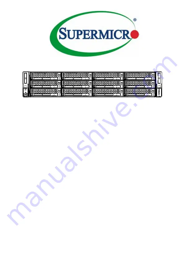
SC826 Series Chassis

USER’S MANUAL 


Revision 2.0c

SC826BE1C-R920LPB

SC826BE1C-R920WB

SC826BE2C-R920LPB

SC826BE2C-R920WB

SC826BA-R1K28LPB

SC826BA-R1K28WB

SC826BE26-R1K28LPB

SC826BE26-R1K28WB

SC826BE16-R1K28LPB

SC826BE16-R1K28WB

SC826E26-R1200LPB

SC826E26-R1200UB

SC826E16-R1200LPB

SC826E16-R1200UB

SC826A-R1200LPB

SC826A-R1200UB

SC826BA-R920LPB

SC826BA-R920UB

SC826BA-R920WB

SC826BE26-R920LPB

SC826BE26-R920UB

SC826BE26-R920WB

SC826BE16-R920LPB

SC826BE16-R920UB

SC826BE16-R920WB

SC826TQ-R800LPV(B)

SC826TQ-R800UB

SC826TQ-R500LPB

SC826E16-R500LPB

SC826BE1C4-R1K23LPB

SC826BE1C4-R1K23WB

Summary of Contents for SC826 Series

Page 1: ...C826BE16 R1K28LPB SC826BE16 R1K28WB SC826E26 R1200LPB SC826E26 R1200UB SC826E16 R1200LPB SC826E16 R1200UB SC826A R1200LPB SC826A R1200UB SC826BA R920LPB SC826BA R920UB SC826BA R920WB SC826BE26 R920LPB SC826BE26 R920UB SC826BE26 R920WB SC826BE16 R920LPB SC826BE16 R920UB SC826BE16 R920WB SC826TQ R800LPV B SC826TQ R800UB SC826TQ R500LPB SC826E16 R500LPB SC826BE1C4 R1K23LPB SC826BE1C4 R1K23WB ...

Page 2: ...TWARE OR DATA STORED OR USED WITH THE PRODUCT INCLUDING THE COSTS OF REPAIRING REPLACING INTEGRATING INSTALLING OR RECOVERING SUCH HARDWARE SOFTWARE OR DATA Any disputes arising between manufacturer and customer shall be governed by the laws of Santa Clara County in the State of California USA The State of California County of Santa Clara shall be the exclusive venue for the resolution of any such...

Page 3: ...ans It provides information for the installation and use of the chassis Installation and maintenance should be performed by experienced technicians only This document lists compatible parts available when this document was published Refer to the Supermico website for updates on supported parts and configurations ...

Page 4: ...Power Disconnection Warning 2 6 Equipment Installation 2 8 Restricted Area 2 9 Battery Handling 2 10 Redundant Power Supplies 2 12 Backplane Voltage 2 13 Comply with Local and National Electrical Codes 2 14 Product Disposal 2 15 Hot Swap Fan Warning 2 16 DC Power Supply 2 18 DC Power Disconnection 2 20 Hazardous Voltage or Energy Present on DC Power Terminals 2 21 Chapter3 System Interface 3 1 Ove...

Page 5: ...ards 4 12 Expansion Cards for an LP Model Chassis 4 12 Expansion Cards for a W or U Model Chassis 4 12 4 6 Installing the Air Shroud 4 15 Checking the Airflow 4 16 4 7 System Maintenance 4 17 System Fans 4 17 Power Supply 4 19 Power Distributor 4 20 Optional Front Bezel 4 21 Chapter 5 Rack Installation 5 1 Unpacking the System 5 1 5 2 Preparing for Setup 5 1 Choosing a Setup Location 5 1 5 3 Warni...

Page 6: ...ack Rails 5 8 Appendix A SC826 Chassis Cables Appendix B SC826 Power Supply Specifications Appendix C BPN SAS 826TQ Backplane Specifications Appendix D BPN SAS 826A Backplane Specifications Appendix E BPN SAS2 826EL Backplane Specifications Appendix F BPN SAS3 826EL Backplane Specifications Appendix G BPN SAS3 826EL1 N4 Backplane Specifications ...

Page 7: ...m Level SC826BE16 R1K28LPB 12x SAS SATA 2 opt single expander SAS2 backplane 7x LP 1280W Redundant Platinum Level SC826BE16 R1K28WB 12x SAS SATA 2 opt single expander SAS2 backplane 4x FH 3x LP 1280W Redundant Platinum Level SC826E16 R1200LPB 12x SAS SATA 7x LP 1200W Redundant Gold Level SC826E16 R1200UB 12x SAS SATA 4x FF 1x UIO 3x LP 1200W Redundant Gold Level SC826E26 R1200LPB 12x SAS SATA 7x L...

Page 8: ...al expander SAS2 backplane 4X FH 3x LP 920W Redundant Platinum Level SC826BE16 R920LPB 12x SAS SATA 2 opt single expander SAS2 backplane 7x LP 920W Redundant Platinum Level SC826BE16 R920UB 12x SAS SATA 2 opt single expander SAS2 backplane 4X FH 2x LP 920W Redundant Platinum Level SC826BE16 R920WB 12x SAS SATA 2 opt single expander SAS2 backplane 4x FH 3x LP 920W Redundant Platinum Level SC826TQ R...

Page 9: ...onal 2 5 hot swap drives for OS mirroring System Power Different models offer redundant power supply modules of several different watt ages Front Control Panel The control panel provides a monitoring and control interface LEDs indicate system status and buttons control system power Cooling System The system includes three 80mm hot swap fans ...

Page 10: ...e Address Super Micro Computer B V Het Sterrenbeeld 28 5215 ML s Hertogenbosch The Netherlands Tel 31 0 73 6400390 Fax 31 0 73 6416525 Email sales supermicro nl General Information support supermicro nl Technical Support rma supermicro nl Customer Support Web Site www supermicro nl Asia Pacific Address Super Micro Computer Inc 3F No 150 Jian 1st Rd Zhonghe Dist New Taipei City 235 Taiwan R O C Tel...

Page 11: ... must be mailed when service is complete For faster service RMA authorizations may be requested online http www supermicro com support rma Whenever possible repack the chassis in the original Supermicro carton using the original packaging material If these are no longer available be sure to pack the chassis securely using packaging material to surround the chassis so that it does not shift within ...

Page 12: ...SC826 Chassis Manual 1 6 Notes ...

Page 13: ... or configuring components in the Supermicro chassis These warnings may also be found on our web site at http www supermicro com about policies safety_information cfm Warning This warning symbol means danger You are in a situation that could cause bodily injury Before you work on any equipment be aware of the hazards involved with electrical circuitry and be familiar with standard practices for pr...

Page 14: ...o que le ayudará a encontrar el texto traducido en el apartado de traducciones que acompaña a este dispositivo GUARDE ESTAS INSTRUCCIONES IMPORTANTES INFORMATIONS DE SÉCURITÉ Ce symbole d avertissement indique un danger Vous vous trouvez dans une situation pouvant entraîner des blessures ou des dommages corporels Avant de travailler sur un équipement soyez conscient des dangers liés aux circuits é...

Page 15: ... aan enige apparatuur gaat werken dient u zich bewust te zijn van de bij een elektrische installatie betrokken risico s en dient u op de hoogte te zijn van de standaard procedures om ongelukken te voorkomen Gebruik de nummers aan het eind van elke waarschuwing om deze te herleiden naar de desbetreffende locatie BEWAAR DEZE INSTRUCTIES ً ف اًك أى ٌوكي حالة ً ف تتسبب اصابة جسذٌة الزهز هذا ًٌ ٌع خطز ...

Page 16: ...ión antes de conectar el sistema a la red de alimentación Attention Avant de brancher le système sur la source d alimentation consulter les directives d installation 設置手順書 システムを電源に接続する前に 設置手順書をお読み下さい ال إرشادات اقر تركيب توصيل قبل إلى النظام للطاقة مصدر לקרוא יש למקור המערכת חיבור לפני התקנה הוראות את מתח 주의 시스템을 전원에 연결하기 전에 설치 안내를 읽어주십시오 Waarschuwing Raadpleeg de installatie instructies voordat u...

Page 17: ...liza el sistema de protección contra cortocircuitos o sobrecorrientes del edificio Asegúrese de que el dispositivo de protección no sea superior a 60VDC 20A Attention Pour ce qui est de la protection contre les courts circuits surtension ce produit dépend de l installation électrique du local Vérifiez que le courant nominal du dispositif de protection n est pas supérieur à 60VDC 20A על מסתמך זה מו...

Page 18: ...r es auf den Chassisinnenraum zurückgreift um Systemsbestandteile anzubringen oder zu entfernen Warning The system must be disconnected from all sources of power and the power cord removed from the power supply module s before accessing the chassis interior to install or remove system components 경고 이 제품은 전원의 단락 과전류 방지에 대해서 전적으로 건물의 관련 설비에 의존합니다 보호장치의 정격이 반드시 60V 볼트 20A 암페어 를 초과하지 않도록 해야 합니다 Waarsc...

Page 19: ...r ou enlever des composants de systéme חשמלי ניתוק מפני אזהרה אזהרה החשמל מקורות מכל המערכת את לנתק יש להסיר ויש מהספק החשמלי כבל את התקנ לצורך המארז של הפנימי לחלק גישה לפני ת הסר או ת רכיבים فصم يجب اننظاو جميع من مصادر انطاقت وإزانت انكهرباء سهك من وحدة امداد انطاقت قبم إنى انىصىل انداخهيت انمناطق ن ههيكم إزانت أو نتثبيج مكىناث الجهاز 경고 시스템에 부품들을 장착하거나 제거하기 위해서는 섀시 내부에 접근하기 전에 반드시 전원 공급장치로부터 연...

Page 20: ...et werden Advertencia Solamente el personal calificado debe instalar reemplazar o utilizar este equipo Attention Il est vivement recommandé de confier l installation le remplacement et la maintenance de ces équipements à des personnels qualifiés et expérimentés אזהרה רש בלבד מוסמך צוות את להחליף להתקין אי הציוד עבור שירות לתת או הציוד والمدربيه و لتزكيب استبدال أو خدمة الجهاس هذا يسمح أن يجب فقط ا...

Page 21: ...n in Bereichen mit beschränktem Zutritt vorgesehen Der Zutritt zu derartigen Bereichen ist nur mit einem Spezialwerkzeug Schloss und Schlüssel oder einer sonstigen Sicherheitsvorkehrung möglich Advertencia Esta unidad ha sido diseñada para instalación en áreas de acceso restringido Sólo puede obtenerse acceso a una de estas áreas mediante la utilización de una herramienta especial cerradura con ll...

Page 22: ...ىص َمكن ً إن ىل منطقت محظورة فقط استخذاو خالل من خاصت أداة أو ٌ أ نال أخري وسُهت مألما ومفتاح قفم 경고 이 장치는 접근이 제한된 구역에 설치하도록 되어있습니다 특수도구 잠금 장치 및 키 또는 기타 보안 수단을 통해서만 접근 제한 구역에 들어갈 수 있습니다 Waarschuwing Dit apparaat is bedoeld voor installatie in gebieden met een beperkte toegang Toegang tot dergelijke gebieden kunnen alleen verkregen worden door gebruik te maken van speciaal gereedschap slot en sleut...

Page 23: ...tipo o el equivalente recomendado por el fabricante Desechar las baterías gastadas según las instrucciones del fabricante אזהרה סכנת קיימת פיצוץ תקינה לא בדרך והוחלפה במידה הסוללה של להחליף יש בסוג הסוללה את מ התואם חברת מומל יצרן צת הסוללות סילוק המשומשות לבצע יש היצרן הוראות לפי خطر هناك من اسحبذال حالة في انفجار البطارية صحيحة غير بطريقة فعليل البطارية اسحبذال فقط النىع بنفس يعادلها ما أو مما أ...

Page 24: ...té peut avoir plus d une connexion d alimentation Pour supprimer toute tension et tout courant électrique de l unité toutes les connexions d alimentation doivent être débranchées Redundant Power Supplies Warning This unit might have more than one power supply connection All connections must be removed to de energize the unit 冗長電源装置 このユニッ トは複数の電源装置が接続されている場合があります ユニッ トの電源を切るためには すべての接続を取り外さなければなりませ...

Page 25: ...uidado cuando lo revise Attention Lorsque le système est en fonctionnement des tensions électriques circulent sur le fond de panier Prendre des précautions lors de la maintenance Warning Hazardous voltage or energy is present on the backplane when the system is operating Use caution when servicing قد لهذا يكون ال جهاز اتصاالت عدة بوحدات الطاقة امداد إزالة يجب االتصاالت كافة لعسل ال وحدة عن الكهربا...

Page 26: ...be cumplir con las normas de electricidad locales y nacionales هناك خطز مه الكهزبائي التيار على المىجىدة أوالطاقة اللىحة يكىن عندما النظام يعمل عند حذرا كه خدمة الجهاس هذا 경고 시스템이 동작 중일 때 후면판 Backplane 에는 위험한 전압이나 에너지가 발생 합니다 서비스 작업 시 주의하십시오 Waarschuwing Een gevaarlijke spanning of energie is aanwezig op de backplane wanneer het systeem in gebruik is Voorzichtigheid is geboden tijdens het onderhou...

Page 27: ...ىاويه والىطىية المحلية المتعلقة بالكهرباء Attention L équipement doit être installé conformément aux normes électriques nationales et locales 경고 현 지역 및 국가의 전기 규정에 따라 장비를 설치해야 합니다 Waarschuwing Bij installatie van de apparatuur moet worden voldaan aan de lokale en nationale elektriciteitsvoorschriften 製品の廃棄 この製品を廃棄処分する場合 国の関係する全ての法律 条例に従い処理する必要が あります 警告 本产品的废弃处理应根据所有国家的法律和规章进行 警告 本產品的廢棄處理應根據所有國家的法律和...

Page 28: ...nt Renseignez vous auprès de l organisme compétent Warning The fans might still be turning when you remove the fan assembly from the chassis Keep fingers screwdrivers and other objects away from the openings in the fan assembly s housing Hot Swap Fan Warning המוצר סילוק אזהרה ו להנחיות בהתאם להיות חייב זה מוצר של סופי סילוק המדינה חוקי النهائي التخلص من المنتج هذا معه التعامل ينبغي ل وفقا جميع الى...

Page 29: ...garde à ce que doigts tournevis et autres objets soient éloignés du logement du bloc ventilateur אזהרה חלקי את מסירים כאשר יש עובדים עדיין והמאווררים יתכן מהמארז המאוורר להרחיק ל המאוורר בתוך מהפתחים שונים עבודה וכלי האצבעות את בטוח מרחק انممكه مه انمراوح أن تسال ال إزانة تدورعند كتهة انمروحة انهيكم مه يجب إبقاء األصابع و انبراغي مفكات األشياء مه وغيرها بعيدا عه انفتحات في كتهة انمروحة 경고 섀시로부터 팬 ...

Page 30: ...e sollten die angemessene Größe für die Drähte haben und sowohl die Isolierung als auch den Leiter festklemmen Advertencia Cuando se necesite hilo trenzado utilizar terminales para cables homologados tales como las de tipo bucle cerrado o espada con las lengüetas de conexión vueltas hacia arriba Estos terminales deberán ser del tamaño apropiado para los cables que se utilicen y tendrán que sujetar...

Page 31: ...اهنإ ةقفاوملا اهيلع لثم ةقلح ةقلغم وأ ءايشألا اهئامسأب ةيقيقحلا عونلا عم تاورعلا ةبولقم يغبنيو هذهل تاءاهنإلا نوكي مجحلا بسانملا كالسألل بجيو حبك لك نم لزعلا لصومو Waarschuwing Wanneer geslagen bedrading vereist is dient u bedrading te gebruiken die voorzien is van goedgekeurde aansluitingspunten zoals het gesloten lus type of het grijperschop type waarbij de aansluitpunten omhoog wijzen Deze aans...

Page 32: ...la alimentación del circuito de corriente continua CC esté cortada OFF Attention Avant de pratiquer l une quelconque des procédures ci dessous vérifier que le circuit en courant continu n est plus sous tension امدنع نوكي ابولطم كالسألا نيذلا تعطقت مهب لبسلا مادختساو كالسألا ءاهنإ ةقفاوملا اهيلع لثم ةقلح ةقلغم وأ ءايشألا اهئامسأب ةيقيقحلا عونلا عم تاورعلا ةبولقم يغبنيو هذهل تاءاهنإلا نوكي مجحلا بسا...

Page 33: ...nals are not in service Be sure uninsulated conductors are not accessible when cover is in place Warning Hazardous Voltage or Energy Present on DC Power Terminals Warnung In mit Gleichstrom betriebenen Terminals kann es zu gefählicher Spannung kommen Die Terminals müssen abgedeckt werden wenn sie nicht in Betrieb sind Stellen Sie bei Benutzung der Abdeckung sicher dass alle nicht isolierten stromf...

Page 34: ...z vous que les conducteurs non isolés ne sont pas accessibles lorsque le couvercle est en place دق دهجلا ةرطخلا وأ ةقاطلا نوكت ةدوجوم ىلع تاطحم ةقاطلا ةمصاعلا لادبتسا ءاطغ امئاد امدنع تاطحملا تسيل يف ةمدخلا امم ال كش هيف تالصوملا ريغ لوزعم ال نكمي لوصولا اهيلإ امدنع ءاطغلا يف هناكم Waarshuwing Op DC aansluitingspunten kunnen zich gevaarlijke voltages of energieën voordoen Plaats altijd de afsluiti...

Page 35: ...tem Interface 3 1 Overview The chassis includes A control panel on the front that includes power buttons and status monitoring lights Status lights on externally accessable hard drives Status lights for the power supply Figure 4 1 Control Panel ...

Page 36: ...ndby power To perform many maintenance tasks you must unplug system before servicing Reset The reset button is used to reboot the system NIC2 Indicates network activity on GLAN2 when flashing 3 2 Control Panel Buttons The chassis includes two push buttons that control power to the system Power Indicates power is being supplied to the system power supply units This LED should normally be illuminate...

Page 37: ...cal UID has been activated Use this function to locate the server in a rack mount environment Blinking blue Remote UID is on Use this function to identify the server from a remote location NIC1 Indicates network activity on GLAN1 when flashing Overheating There are several possible responses if the system overheats Overheat Temperature Setting Some backplanes allow the overheat temperature to be s...

Page 38: ... blinks on and off when that particular drive is being accessed This function is controlled by the backplane Red When illuminated this LED indicates a drive failure You should be notified by your system management software 3 5 Power Supply LEDs On the rear of the power supply module an LED displays the status Solid Green When illuminated indicates that the power supply is on Solid Amber When illum...

Page 39: ...se listed in the setup instructions 4 1 Removing Power from the System Before performing most setup or maintenance tasks use the following procedure to ensure that power has been removed from the system 1 Use the operating system to power down the system or node following the on screen prompts 2 After the system has completely shut down carefully grasp the head of the power cord and gently pull it...

Page 40: ...ss the release tabs to remove the cover from the locked position Press both tabs at the same time 4 Once the top cover is released from the locked position slide the cover toward the rear of the chassis 5 Lift the cover off the chassis Caution Except for short periods of time do not operate the system without the cover in place The chassis cover must be in place to allow proper airflow and prevent...

Page 41: ...from the chassis These carriers also help promote proper airflow for the drive bays The SC826B models also support an optional a 2 5 hard drive cage which holds up to two additional 2 5 hard drives Instructions on the following pages Removing a 3 5 Hard Drive Carrier Removing Hard Drive Carriers 1 Press the release button on the drive tray This extends the drive bay handle 2 Use the handle to pull...

Page 42: ... Drive from the Carrier Drive Carrier Dummy Drive 1 1 Installing 3 5 Hard Drives Caution Except for short periods of time swapping hard drives do not operate the server with the hard drive bays empty Note Your operating system must have RAID support to enable the hot swap capability of the drives ...

Page 43: ...rrier with the printed circuit board side facing down 5 Carefully align the mounting holes in the hard drive and the carrier Make sure the bottom of the hard drive and bottom of the hard drive carrier are flush 6 Secure the hard drive using all six screws 7 Replace the drive carrier into the chassis Make sure to close the drive tray using the drive carrier handle Hard Drive Carrier SAS SATA Hard D...

Page 44: ...hout powering down the server Installing the 2 5 Rear Hard Drive Cage 1 Power down as described in section 4 1 lay the chassis on a flat stable surface and remove the chassis cover 2 Orient the 2 5 rear hard drive cage as shown aligning the opening at the end of the cage with the opening at the back of the chassis 3 Place the hard drive cage into the chassis 4 Secure the front of the hard drive ca...

Page 45: ... 6 1 4 5 Secure the top of the hard drive cage to the chassis frame with two screws fastened at the upper edge of the hard drive cage above the opening of the hard drive cage 6 Secure the back of the hard drive cage to the chassis with one screw as shown above 7 Replace the power cords and power up the server ...

Page 46: ...es in the carrier marked SAS or SATA to aid in correct installation 3 Secure the drive to the carrier with four screws Use the four M3 flat head screws included in the HDD bag of your accessory box Note that the screws used to secure the dummy drive to the tray cannot be used to secure the hard drive 4 Insert the drive and carrier into its bay vertically keeping the carrier oriented so that the re...

Page 47: ...g the outside of the chassis place the shield into the space provided I O Shield Figure 4 10 I O Shield Placement 4 4 Installing the Motherboard Riser Card Bracket W or U Models only Some SC826 models incorporate riser cards to accept full height expansion cards This riser card is mounted on a chassis bracket that if it is installed must be removed before installing the motherboard See Section 4 5...

Page 48: ...tions used by most motherboards These standoffs accept the rounded Phillips head screws included in the accessories packaging Some motherboards require additional screws for heatsinks general components and or non standard security Optional standoffs are included to these motherboards To use an optional standoff you must place the hexagonal screw through the bottom the chassis and secure the screw...

Page 49: ...hassis b Secure the screw with the hexagon nut rounded side up 4 Compare the mounting holes in the motherboard with those in the chassis then add and remove standoffs as needed 5 Secure the motherboard to the chassis using the rounded Phillips head screws Do not exceed eight inch pounds of torque 6 Secure the CPU s heatsinks and other components to the motherboard as described in the motherboard d...

Page 50: ...remove the cover 2 In the rear of the chassis remove the blank PCI shield that is pre installed covering the expansion slot Figure 5 11 Remove an LP Expansion Card Slot Shield 3 Slide the expansion card into the expansion slot on the motherboard while aligning it with the chassis slot in the rear of the chassis 4 Secure the expansion card shield onto the rear of the chassis with a screw Expansion ...

Page 51: ...e UIO slot in the motherboard while aligning it with slot in the rear of the chassis 4 Secure the shield to the rear of the chassis with the lever Installing an Expansion Card for a W or U Model Chassis 1 If this is the first expansion card start by locating the riser card bracket in your chassis accessory bag and one or two riser cards which are purchased separately One riser card accomodates the...

Page 52: ...the rear of the chassis this clamp is near the middle just left of the low profile PCI slots Unscrew the single screw that secures the clamp and slide the clamp to the left away from the shields 6 Insert the expansion card into a slot on the riser card while aligning the expansion card backplate with the open slot in the rear of the chassis Repeat for other expansion cards if you are installing mo...

Page 53: ...ove the chassis cover 2 If necessary move any cables that interfere with the air shroud placement 3 Place the air shroud in the chassis The air shroud fits just behind the two fans closest to the power supply Slide the air shroud into the grooves just behind the fan rack 4 If necessary the perforated tabs on either side of the air shroud may be removed to ensure a proper fit Note that if a 16 DIMM...

Page 54: ...odically Do not operate the server without drives or drive carriers in the drive bays Use only recommended server parts Make sure no wires or foreign objects obstruct air flow through the chassis Pull all excess cabling out of the airflow path or use shorter cables The control panel LEDs inform you of system status See Chapter 3 System Interface for details on the LEDs and the control panel button...

Page 55: ...ended period of time with the chassis open 2 Power down the server as described in section 4 1 lay the chassis on a flat stable surface and remove the chassis cover 3 Remove the failed fan s power cord from the motherboard 4 Press the fan release tab to lift the failed fan from the fan tray and pull it completely from the chassis 5 Place the new fan into the vacant space in the fan tray while maki...

Page 56: ...SC826 Chassis Manual 4 18 Figure 4 16 Placing the System Fan in the Chassis 3 5 ...

Page 57: ... supply is operating Replacement units can be ordered directly from Supermicro Power Supply Changing the Power Supply 1 Remove the AC power cord from the back of the power supply module that you want to replace 2 Push the release tab on the rear of the power supply 3 Pull the module out of the power supply bay using the handle 4 Push the new power supply module into the power bay until it clicks 5...

Page 58: ...therboard backplane and other components 3 Remove both power supplies 4 Locate the power distributor between the power supply and the fan row 5 Remove the three screws securing the power supply 6 Gently pull the power distributor from the chassis carefully guiding all the cables through the power distributor housing 7 Slide the new power distributor module into the power distributor housing Make t...

Page 59: ...tup and Maintenance Optional Front Bezel The SC826 chassis supports an optional full face locking front bezel for added security It can be ordered separately from the Supermico web site referencing part number MCP 210 82601 0B ...

Page 60: ...SC826 Chassis Manual 4 22 Notes ...

Page 61: ... Avoid areas where heat electrical noise and electromagnetic fields are generated A nearby grounded power outlet is required The box your chassis was shipped in should include two sets of rail assemblies two rail mounting brackets and the mounting screws to mount the system into the rack Please read this chapter in its entirety before beginning the installation procedure Choosing a Setup Location ...

Page 62: ...ay cause the rack to become unstable General Server Precautions Review the electrical and general safety precautions that came with the components you are adding to your chassis Determine the placement of each component in the rack before you install the rails Install the heaviest server components on the bottom of the rack first and then work upward Use a regulating uninterruptible power supply U...

Page 63: ...nsideration of equipment nameplate ratings should be used when addressing this concern Reliable Ground A reliable ground must be maintained at all times To ensure this the rack itself should be grounded Particular attention should be given to power supply connections other than the direct connections to the branch circuit i e the use of power strips etc Warning To prevent bodily injury when mounti...

Page 64: ...his rail will fit a rack between 26 5 and 36 4 deep Identifying the Sections of the Rack Rails The chassis package includes two rail assemblies Each assembly consists of three sections An inner rail that secures directly to the chassis an outer rail that secures to the rack and a middle rail which extends from the outer rail These assemblies are specifically designed for the left and right side of...

Page 65: ...ck when when the chassis is pulled out for servicing To mount the rail onto the chassis first release the inner rail from the outer rails Releasing Inner Rail from the Outer Rails 1 Pull the inner rail out of the outer rail until it is fully extended as illustrated below 2 Press the locking tab down to release the inner rail 3 Pull the inner rail all the way out 4 Repeat for the other outer rail 1...

Page 66: ...nner rail firmly against the side of the chassis aligning the hooks on the side of the chassis with the holes in the inner rail 3 Slide the inner rail forward toward the front of the chassis until the quick release bracket snaps into place securing the rail to the chassis 4 Optionally you can further secure the inner rail to the chassis with a screw 5 Repeat for the other inner rail Figure 5 4 Inn...

Page 67: ... secure the outer rails to the rack 4 Pull out the rear of the outer rail adjusting the length until it just fits within the posts of the rack 5 Hang the hooks of the rear section of the outer rail onto the square holes on the rear of the rack Take care that the proper holes are used so the rails are level If desired use screws to secure the rear of the outer rail to the rear of the rack Stability...

Page 68: ...ated above 2 Align the inner rails of the chassis with the outer rails on the rack 3 Slide the inner rails into the outer rails keeping the pressure even on both sides When the chassis has been pushed completely into the rack it should click into the locked position 4 Optional screws may be used to hold the front of the chassis to the rack Note The figure above is for illustrative purposes only Al...

Page 69: ...Length Description CBL 0087 Cable 50 8 cm 20 Round 16 pin to 16 pin ribbon front panel cable CBL 0160L Cord US power cord 16 AWG PB free CBL 0217L Cable 16 pin control panel converter cable for SC826 PBF CBL 0157L Cable 22 86 cm 9 8 pin to 8 pin ribbon cable for SGPIO PB free CBL 0191L Cable 50 cm 19 685 20 pin to 20 pin cable for control panel CBL 0139L Wire 50 cm 19 685 IDE 80 Wire cable for DVD...

Page 70: ... one SFF 8484 32 pin connector on one end and four SAS connectors seven pins each at the other This cable connects from the Host motherboard or other controller to the backplane SAS hard drive port Cable Name SAS Cable Quantity 1 Part CBL 0175L Alt Name Big Four Description This cable has one iPass SFF 8087 Mini SAS connector 36 pin at one end and four SAS connectors on the other end This cable co...

Page 71: ...0 pin CBL 0059 7 9 20 cm 8 pin CBL 0062 7 9 20 cm 4 pin CBL 0060 7 9 20 cm Front Panel to the Motherboard The SC826 chassis includes a cable to connect the chassis front panel to the motherboard If your motherboard uses a different connector use the following list to find a compatible cable Front Panel to Motherboard Cable Ribbon Cable Number of Pins Front Panel Number of Pins Motherboard Cable Pa...

Page 72: ...SC826 Chassis Manual A 4 Notes ...

Page 73: ... 4 Amp 12V 66 Amp 5V 30 Amp 3 3V 24 Amp 12V 0 6 Amp 500W MFR Part PWS 501P 1R AC Input 100 240 V 50 60 Hz 6 1 2 6 Amp DC Output 4 Amp 5V standby 41 7 Amp 12V With Power Distributor 5V 30 Amp 3 3V 24 Amp 12V 0 6 Amp 920W MFR Part PWS 920P SQ AC Input 1000W Output 100 140V 12 8A 50 60Hz 1280W Output 180 240V 8 6A 50 60Hz DC Output 1000W 12V 83A 5Vsb 4A 1280W 12V 106 7A 5Vsb 4A With Power Distributor...

Page 74: ...280W Output 180 240V 8 6A 50 60Hz DC Output 1000W 12V 83A 5Vsb 4A 1280W 12V 106 7A 5Vsb 4A 1200W MFR Part PWS 1K21P 1R AC Input 100 140V 50 60Hz 8 11 Amp 180 240V 50 60Hz 5 5 8 Amp DC Output 12V 1000W 83 Amp 100 140V 1200W 100 Amp 180 240V 5Vsb 4A DC Output with PDB 5V 50 Amp 3 3V 30 Amp 12V 0 6 Amp ...

Page 75: ...tacts When handling chips or modules avoid touching their pins Put the card and peripherals back into their antistatic bags when not in use C 2 General Safety Guidelines Always disconnect power cables before installing or removing any components from the computer including the BPN SAS 826TQ backplane Disconnect the power cable before installing or removing any cables from the BPN SAS 826TQ backpla...

Page 76: ... quality performance This manual reflects BPN SAS 826TQ Revision 3 1 the most current release avail able at the time of publication Always refer to the Supermicro Web site at www su permicro com for the latest updates compatible parts and supported configurations To avoid personal injury and property damage carefully follow all the safety steps listed below when accessing your system or handling t...

Page 77: ...46 7 SideBand Connector 1 JP66 8 SideBand Connector 2 JP68 9 SideBand Connector 3 JP75 10 SAS Port 0 J5 11 SAS Port 1 J6 12 SAS Port 2 J7 13 SAS Port 3 J8 14 SAS Port 4 J10 15 SAS Port 5 J12 16 SAS Port 6 J14 17 SAS Port 7 J16 18 SAS Port 8 J22 19 SAS Port 9 J23 20 SAS Port 10 J24 21 SAS Port 11 J25 JP46 1 4 JP13 1 4 JP10 1 4 Y2 F1 F2 F4 F5 F7 F8 F3 F6 F9 U40 1 11 12 22 23 33 34 44 JP66 JP68 JP75 ...

Page 78: ...ity status of each SAS drive The activity LED headers are located on the front panel For the activity lead headers to work properly connect to them using a 10 pin LED cable This is only used when the activity LED is not supported by the hard drive SAS Activity LED Header Pin Definitions Pin Definition Pin Definition 1 ACT IN 8 6 ACT IN 12 2 ACT IN 9 7 ACT IN 13 3 ACT IN 10 8 ACT IN 14 4 ACT IN 11 ...

Page 79: ...ing 1 Controller ID SB6 4 SGPIO SDOUT I2 C Reset 3 GND SB2 6 GND SB3 5 SGPIO SLOAD I2 C SDA 8 Backplane ID SB7 7 SGPIO SCLOCK 12 C SCL 10 No Connec tion 9 No Connec tion Backplane Main Power 4 Pin Connector Pin Definition 1 12V 2 and 3 Ground 4 5V 6 Backplane Main Power Connectors The 4 pin connectors designated JP10 JP13 and JP46 provide power to the backplane See the table on the right for pin d...

Page 80: ...16 J14 J12 J10 J22 JP26 JP47 U4 U36 U1 U29 U31 U32 U61 U43 U45 U18 U30 U52 U25 U26 3 1 REV SAS826TQ MACH FINISH 30 ANGLE SPECIFIED DIMENSIONS UNLESS OTHERWISE XXX XX X 010 03 1 TOLERANCES DECIMAL ARE IN INCHES Shen Nina DESINGER DATE 10 31 2007 PROJECT NAME SAN JOSE CA 95131 DESIGNED BY SUPERMICRO U S A www supermicro com TEL 408 503 8000 FAX 408 503 8008 SILKSCREEN PRIMARY SIDE SUPER R SUPER SUPE...

Page 81: ...84 Pin 1 2 SGPIO mode enable Pin 2 3 I2 C mode enable I2 C and SGPIO Modes and Jumper Settings This backplane can utilize I2 C or SGPIO SGPIO is the default mode and can be used without making changes to your jumpers The following information details which jumper must be configured to use SGPIO mode or restore your backplane to I2 C mode ...

Page 82: ...54 R166 R183 R261 R263 R265 R122 R124 R128 R155 R6 R139 R264 R266 R324 R156 R138 R185 R131 R133 R168 R136 R271 R272 R137 R134 R135 1 JP25 1 JP45 1 JP84 D79 D78 D77 D76 D71 D70 D68 D67 D66 D65 D64 D63 D62 D61 D60 D59 D58 D57 D56 D55 JP37 JP95 JP52 U24 U62 U63 U64 U65 U67 U69 U70 U71 U72 U20 U39 JP69 JP78 RP1 RP4 U2 U49 J7 J6 J5 J8 J24 J23 J25 J16 J14 J12 J10 J22 JP26 JP47 U4 U36 U1 U29 U31 U32 U61 ...

Page 83: ...S U P E R S U P E R S U P E R S U P E R S U P E R S U P E R S U P E R R R R R R R R R R R FAIL 11 ACT 11 FAIL 10 ACT 10 FAIL 9 ACT 9 FAIL 8 ACT 8 FAIL 6 ACT 6 ACT 7 FAIL 7 ACT 5 FAIL 5 ACT 4 FAIL 4 8 9 10 11 7 6 5 4 3 2 1 0 SAS SAS SAS SAS SAS SAS SAS SAS SAS SAS SAS SAS FAIL 3 ACT 3 ACT 2 FAIL 2 ACT 1 FAIL 1 ACT 0 FAIL 0 C 8 Rear Connectors and LED Indicators Rear SAS SATA Connectors Rear Connect...

Page 84: ...C 10 SC826 Chassis Manual Notes ...

Page 85: ... discharge Touch a grounded metal object before removing a component from the antistatic bag Handle the backplane by its edges only do not touch its components peripheral chips memory modules or gold contacts When handling chips or modules avoid touching their pins Put the card and peripherals back into their antistatic bags when not in use D 2 General Safety Guidelines Always disconnect power cab...

Page 86: ...own in this manual D 4 Introduction to the BPN SAS 826A Backplane The BPN SAS 826A backplane has been designed to utilize the most up to date technology available providing your system with reliable high quality performance This manual reflects BPN SAS 826A Revision 1 00 the most current release available at the time of publication Always refer to the Supermicro Web site at www supermicro com for ...

Page 87: ...41 JP69 JP78 RP1 U2 JP26 JP47 U18 BAR CODE B B SAS IN 1 SAS IN 2 9072 RST 9071 RST ACT4 ACT11 ACT10 ACT9 ACT8 ACT3 ACT2 ACT1 ACT7 ACT6 ACT5 ACT0 2 3 I2C 1 2 SGPIO JP84 MODE C 2 3 55 1 2 50 C C OPEN 45 JP45 OH 2 TEMP C C C 2 3 55 1 2 50 OPEN 45 JP25 OH 1 TEMP ALARM 1 ALARM 2 ACT_IN 8 11 ACT_IN 0 7 UPGRADE 2 UPGRADE 1 SAS IN 3 I2C 3 I2C 2 I2C 1 BUZZER RESET REV 1 00 SAS826A Front Connectors 1 ACT_IN...

Page 88: ...ity status of each SAS drive The activity LED headers are located on the front panel For the activity lead headers to work properly connect to them using a 10 pin LED cable This is only used when the activity LED is not supported by the hard drive SAS Activity LED Header Pin Definitions Pin Definition Pin Definition 1 ACT IN 8 6 ACT IN 12 2 ACT IN 9 7 ACT IN 13 3 ACT IN 10 8 ACT IN 14 4 ACT IN 11 ...

Page 89: ...the table on the right for pin definitions 7 8 9 SAS Ports The SAS ports are used to connect the SAS drive cables The three connectors are designated SAS IN 1 SAS IN 3 Each of the three connectors has four ports for a total of twelve ports These twelve ports are designated 0 11 and they are also compatible with SATA drives 10 Upgrade Connectors The upgrade connectors designated JP69 and JP78 are u...

Page 90: ...PEN 45 JP25 OH 1 TEMP ALARM 1 ALARM 2 ACT_IN 8 11 ACT_IN 0 7 UPGRADE 2 UPGRADE 1 SAS IN 3 I2C 3 I2C 2 I2C 1 BUZZER RESET REV 1 00 SAS826A JP18 JP35 JP84 JP50 D 7 Front Jumper Locations and Settings Explanation of Jumpers To modify the operation of the backplane jumpers can be used to choose between optional settings Jumpers create shorts between two pins to change the function of the connector Pin...

Page 91: ...ins 1 2 SGPIO mode enable Pins 2 3 I2 C mode enable I2 C and SGPIO Modes and Jumper Settings This backplane can utilize I2 C or SGPIO SGPIO is the default mode and can be used without making changes to your jumpers The following information details which jumper must be configured to use SGPIO mode or restore your backplane to I2 C mode ...

Page 92: ...R CODE B B SAS IN 1 SAS IN 2 9072 RST 9071 RST ACT4 ACT11 ACT10 ACT9 ACT8 ACT3 ACT2 ACT1 ACT7 ACT6 ACT5 ACT0 2 3 I2C 1 2 SGPIO JP84 MODE C 2 3 55 1 2 50 C C OPEN 45 JP45 OH 2 TEMP C C C 2 3 55 1 2 50 OPEN 45 JP25 OH 1 TEMP ALARM 1 ALARM 2 ACT_IN 8 11 ACT_IN 0 7 UPGRADE 2 UPGRADE 1 SAS IN 3 I2C 3 I2C 2 I2C 1 BUZZER RESET REV 1 00 SAS826A Front Panel LEDs LED State Specification Alarm 1 D3 On Overhe...

Page 93: ... FAIL 0 D 8 Rear Connectors and LED Indicators Rear SAS SATA Connectors Rear Connector SAS Drive Number Rear Connector SAS Drive Number SAS 0 SAS SATA HHD 0 SAS 6 SAS SATA HHD 6 SAS 1 SAS SATA HHD 1 SAS 7 SAS SATA HHD 7 SAS 2 SAS SATA HHD 2 SAS 8 SAS SATA HHD 8 SAS 3 SAS SATA HHD 3 SAS 9 SAS SATA HHD 9 SAS 4 SAS SATA HHD 4 SAS 10 SAS SATA HHD 10 SAS 5 SAS SATA HHD 5 SAS 11 SAS SATA HHD 11 Rear LED...

Page 94: ...D 10 SC826 Chassis Manual Notes ...

Page 95: ...omponent from the antistatic bag Handle the backplane by its edges only do not touch its components peripheral chips memory modules or gold contacts When handling chips or modules avoid touching their pins Put the card and peripherals back into their antistatic bags when not in use E 2 General Safety Guidelines Always disconnect power cables before installing or removing any components from the co...

Page 96: ...e at www supermicro com for the latest updates compatible parts and supported configurations E 5 Overview of the BPN SAS2 826EL1 EL2 Backplanes The BPN SAS2 826EL1 and BPN SAS2 826EL2 model backplanes are identical except that the BPN SAS2 826EL2 backplane has duplicate secondary components which are not found on the BPN SAS2 826EL1 The BPN SAS2 826EL2 is divided into a two sections with the prima...

Page 97: ...08 503 8008 SILKSCREEN PRIMARY SIDE SUPER R SUPER SUPER SUPER SUPER SUPER SUPER SUPER SUPER SUPER SUPER SUPER SUPER SUPER SUPER SUPER SUPER SUPER R R R R R R R R R R WWN WWN AB AA DESIGNED IN USA REV 1 01 BPN SAS2 826EL2 E 6 Front Connectors Front Connectors 1 EPP connectors J16 and J17 2 Primary and secondary expander chips 3 Power connectors PWR1 PWR2 and PWR3 4 Fan connectors Fan1 Fan2 and Fan3...

Page 98: ...n definitions Fan Connectors Pin Definition 1 Ground 2 12V 3 Tachometer 2 Primary and Secondary Expander Chips This primary and secondary expander chips allow the backplane to support dual port cas cading and failover configurations 5 8 SAS Ports Primary and secondary SAS ports 9 10 UART Connectors Primary and secondary UART connectors For manufacturer s use only Secondary connector is not present...

Page 99: ...DIMENSIONS UNLESS OTHERWISE XXX XX X 010 03 1 TOLERANCES DECIMAL ARE IN INCHES Teddy Ben DESINGER DATE 2009 12 15 PROJECT NAME SAN JOSE CA 95131 DESIGNED BY SUPERMICRO U S A www supermicro com TEL 408 503 8000 FAX 408 503 8008 SILKSCREEN PRIMARY SIDE SUPER R SUPER SUPER SUPER SUPER SUPER SUPER SUPER SUPER SUPER SUPER SUPER SUPER SUPER SUPER SUPER SUPER SUPER R R R R R R R R R R WWN WWN AB AA DESIG...

Page 100: ...AN_MONITOR_DIS ABLE Open Enabled Default Closed Disabled Enables the fan speed monitor reporting FANFAIL_LED_DIS ABLE Open Enabled Default Closed Disabled Enables the FANFAIL1 LED BUZZER_ENB1 Open Disabled Closed Enabled Buzzer disabled Buzzer enabled The buzzer sound indicates that a condition requiring immediate attention has occurred The buzzer alarm is triggered by one of the following conditi...

Page 101: ...H6 MH5 MH4 4 1 FAN1 4 FAN2 1 FAN3 1 8 J18 1 8 5 Y E 20 R K 10 15 AE 25 28 AH 5 E 20 R K 10 15 AE 25 28 AH SEC_MODE1 1 3 1 SEC_MODE2 1 3 Y2 1 4 EXPDBG1 1 EXPDBG2 1 4 UART_S1 1 4 UART_P1 PRI_MODE1 PRI_MODE2 PRI_I2C1 Q4 R187 JP1 1 4 C408 BCA115 BCA121 C265 C72 R305 C128 C130 C362 EC6 EC10 EC11 EC12 EC13 EC14 EC18 EC7 EC8 EC9 5V 12V GND GND PWR1 5V 12V GND GND PWR2 5V 12V GND GND PWR3 SAS CODE BAR COD...

Page 102: ... R S U P E R S U P E R S U P E R S U P E R S U P E R S U P E R S U P E R S U P E R S U P E R S U P E R S U P E R S U P E R R R R R R R R R R R E 10 Rear Connectors and LED Indicators Rear SAS Connectors Rear Connector SAS Drive Number Rear Connector SAS Drive Number SAS 0 SAS HDD 0 SAS 6 SAS HDD 6 SAS 1 SAS HDD 1 SAS 7 SAS HDD 7 SAS 2 SAS HDD 2 SAS 8 SAS HDD 8 SAS 3 SAS HDD 3 SAS 9 SAS HDD 9 SAS 4...

Page 103: ..._DISABLE 1 BUZZER_ENB1 1 MDIO1 MDIO2 1 ACTLED1 FAN_MONITOR_DISABLE 1 MH9 MH8 MH7 MH6 MH5 MH4 4 1 FAN1 4 FAN2 1 FAN3 1 8 J18 1 8 5 Y E 20 R K 10 15 AE 25 28 AH 5 E 20 R K 10 15 AE 25 28 AH SEC_MODE1 1 3 1 SEC_MODE2 1 3 Y2 1 4 EXPDBG1 1 EXPDBG2 1 4 UART_S1 1 4 UART_P1 PRI_MODE1 PRI_MODE2 PRI_I2C1 Q4 R187 JP1 1 4 C408 BCA115 BCA121 C265 C72 R305 C128 C130 C362 EC6 EC10 EC11 EC12 EC13 EC14 EC18 EC7 EC...

Page 104: ...AX 408 503 8008 SILKSCREEN PRIMARY SIDE SUPER R SUPER SUPER SUPER SUPER SUPER SUPER SUPER SUPER SUPER SUPER SUPER SUPER SUPER SUPER SUPER SUPER SUPER R R R R R R R R R R WWN WWN AB AA DESIGNED IN USA REV 1 01 BPN SAS2 826EL2 SAS HBA Port A Expander 1 Port B Expander 2 Q9 F1 FANFAIL1 A C OVERHEATFAIL1 A C 5V_LED1 A C 12V_LED1 A C ACT18 A C ACT17 A C C367 C366 C365 C353 C352 C134 C133 C132 C121 C120...

Page 105: ...65 C353 C352 C134 C133 C132 C121 C120 C119 EC19 R167 2 1 J16 J19 PRI_J1 PRI_J0 SEC_J0 SEC_J1 BC8 BC518 C157 C395 1 FANFAIL_LED_DISABLE 1 BUZZER_ENB1 1 MDIO1 MDIO2 1 ACTLED1 FAN_MONITOR_DISABLE 1 MH9 MH8 MH7 MH6 MH5 MH4 4 1 FAN1 4 FAN2 1 FAN3 1 8 J18 1 8 5 Y E 20 R K 10 15 AE 25 28 AH 5 E 20 R K 10 15 AE 25 28 AH SEC_MODE1 1 3 1 SEC_MODE2 1 3 Y2 1 4 EXPDBG1 1 EXPDBG2 1 4 UART_S1 1 4 UART_P1 PRI_MOD...

Page 106: ... describes the supported power card for the BPN SAS2 826EL backplane system C38 Q1 BUZZER1 J1 1 12 13 24 R31 R24 R22 R23 R19 R4 R14 R11 R1 R2 R12 R16 R13 R7 R3 R15 R5 R6 R8 R17 R92 R93 R94 R18 R20 R21 R70 F5 F9 F8 F7 F4 F3 F2 F1 C1 C3 U9 U6 D314 D315 D316 U3 U1 EC3 EC2 EC1 C37 C4 C2 C33 C35 C36 D1 A C MH4 MH3 MH2 MH1 JF1 1 2 19 20 C22 U7 J17 1 5 4 1 FAN8 X 4 1 FAN7 X 4 1 FAN6 X 4 1 FAN5 X 4 1 FAN1...

Page 107: ...R R R R R R WWN WWN AB AA DESIGNED IN USA REV 1 01 BPN SAS2 826EL2 HBA HBA HBA Q9 F1 FANFAIL1 A C OVERHEATFAIL1 A C 5V_LED1 A C 12V_LED1 A C ACT18 A C ACT17 A C C367 C366 C365 C353 C352 C134 C133 C132 C121 C120 C119 EC19 R167 2 1 J16 J19 PRI_J1 PRI_J0 SEC_J0 SEC_J1 BC8 BC518 C157 C395 1 FANFAIL_LED_DISABLE 1 BUZZER_ENB1 1 MDIO1 MDIO2 1 ACTLED1 FAN_MONITOR_DISABLE 1 MH9 MH8 MH7 MH6 MH5 MH4 4 1 FAN1...

Page 108: ... 9 inches Part CBL 0110L 02 Length 18 cm 7 inches Description This cable has one SFF 8484 32 pin connector on one end and one iPass SFF 8087 Mini SAS connector 36 pin at the other This cable connects from the HBA to the SAS2 826EL backplane Cable Name iPass to 4 Lane Part CBL 0117 Length 46 cm 18 inches Supported Internal HBA to Backplane Cables Use the following listed cables to create connection...

Page 109: ...R SUPER SUPER SUPER R R R R R R R R R R WWN WWN AB AA DESIGNED IN USA REV 1 01 BPN SAS2 826EL2 Single External Host Bus Adapter HBA Power Card Q9 F1 FANFAIL1 A C OVERHEATFAIL1 A C 5V_LED1 A C 12V_LED1 A C ACT18 A C ACT17 A C C367 C366 C365 C353 C352 C134 C133 C132 C121 C120 C119 EC19 R167 2 1 J16 J19 PRI_J1 PRI_J0 SEC_J0 SEC_J1 BC8 BC518 C157 C395 1 FANFAIL_LED_DISABLE 1 BUZZER_ENB1 1 MDIO1 MDIO2 ...

Page 110: ...le if your external HBA has an InfiniBand connector Description This cable has an InfiniBand connector SFF 8470 on one end and an SFF 8088 1X 26 pin connector at the other end Cable Name SAS InfiniBand to Mini SAS X4 1M cable PBF Part CBL 0200L Length 1 meter Figure E 11 The CBL 0200L Cable ...

Page 111: ...ICRO U S A www supermicro com TEL 408 503 8000 FAX 408 503 8008 SILKSCREEN PRIMARY SIDE SUPER R SUPER SUPER SUPER SUPER SUPER SUPER SUPER SUPER SUPER SUPER SUPER SUPER SUPER SUPER SUPER SUPER SUPER R R R R R R R R R R WWN WWN AB AA DESIGNED IN USA REV 1 01 BPN SAS2 826EL2 Q9 F1 FANFAIL1 A C OVERHEATFAIL1 A C 5V_LED1 A C 12V_LED1 A C ACT18 A C ACT17 A C C367 C366 C365 C353 C352 C134 C133 C132 C121 ...

Page 112: ... 8088 1x to SFF 8088 x1 Ports Single or Dual Placement External cable Description Internal cable Connects the backplane to the host bus adapter or external port Used in single port environments Cable Name BPN SAS EL2 EL1 Backplane Cable Internal w 2 port Cascading Cable 68 cm Part CBL 0167L SFF 8087 to SFF 8088 x1 Ports Single Placement Internal cable Single HBA Configuration Cables Single Port Ca...

Page 113: ...PER SUPER SUPER SUPER SUPER SUPER SUPER SUPER SUPER SUPER SUPER SUPER SUPER SUPER SUPER SUPER R R R R R R R R R R WWN WWN AB AA DESIGNED IN USA REV 1 01 BPN SAS2 826EL2 HBA HBA Q9 F1 FANFAIL1 A C OVERHEATFAIL1 A C 5V_LED1 A C 12V_LED1 A C ACT18 A C ACT17 A C C367 C366 C365 C353 C352 C134 C133 C132 C121 C120 C119 EC19 R167 2 1 J16 J19 PRI_J1 PRI_J0 SEC_J0 SEC_J1 BC8 BC518 C157 C395 1 FANFAIL_LED_DI...

Page 114: ...rts Dual Placement Internal cable Description External cascading cable Connects ports between servers Use one cable for single port connections and two cables for dual port connections Cable Name BPN SAS EL2 EL1 Cascading Cable External 68 cm Part CBL 0166L SFF 8088 x1 to SFF 8088 x1 Ports Single or dual Placement External cable Dual HBA Configuration Cables Dual Port Cable Assembly Figure E 16 Th...

Page 115: ...J19 PRI_J1 PRI_J0 SEC_J0 SEC_J1 BC8 BC518 C157 C395 1 FANFAIL_LED_DISABLE 1 BUZZER_ENB1 1 MDIO1 MDIO2 1 ACTLED1 FAN_MONITOR_DISABLE 1 MH9 MH8 MH7 MH6 MH5 MH4 4 1 FAN1 4 FAN2 1 FAN3 1 8 J18 1 8 5 Y E 20 R K 10 15 AE 25 28 AH 5 E 20 R K 10 15 AE 25 28 AH SEC_MODE1 1 3 1 SEC_MODE2 1 3 Y2 1 4 EXPDBG1 1 EXPDBG2 1 4 UART_S1 1 4 UART_P1 PRI_MODE1 PRI_MODE2 PRI_I2C1 Q4 R187 JP1 1 4 C408 BCA115 BCA121 C265...

Page 116: ... R187 JP1 1 4 C408 BCA115 BCA121 C265 C72 R305 C128 C130 C362 EC6 EC10 EC11 EC12 EC13 EC14 EC18 EC7 EC8 EC9 5V 12V GND GND PWR1 5V 12V GND GND PWR2 5V 12V GND GND PWR3 SAS CODE BAR CODE 1 00 REV BPN SAS2 826EL2 MACH FINISH 30 ANGLE SPECIFIED DIMENSIONS UNLESS OTHERWISE XXX XX X 010 03 1 TOLERANCES DECIMAL ARE IN INCHES Teddy Ben DESINGER DATE 2009 12 15 PROJECT NAME SAN JOSE CA 95131 DESIGNED BY S...

Page 117: ...om the antistatic bag Handle the backplane by its edges only do not touch its components peripheral chips memory modules or gold contacts When handling chips or modules avoid touching their pins Put the card and peripherals back into their antistatic bags when not in use F 2 General Safety Guidelines Always disconnect power cables before installing or removing any components from the computer incl...

Page 118: ...site at www supermicro com for the latest updates compatible parts and supported configurations F 5 Overview of the BPN SAS3 826EL1 EL2 Backplanes The BPN SAS3 826EL1 and BPN SAS3 826EL2 model backplanes are identical except that the BPN SAS3 826EL2 backplane has duplicate secondary components which are not found on the BPN SAS3 826EL1 The BPN SAS3 826EL2 is divided into a two sections with the pr...

Page 119: ...U22 J23 J22 J18 J19 JPW2 JPW1 JPW3 U34 U17 U14 U21 U16 U20 U6 C52 J16 J17 MH7 MH6 MH9 MH8 MH5 MH1 MH2 MH3 MH4 U30 U24 U7 U27 JP1 R97 C511 C5 J J I2C 4 SEC UART PRI UART 12V 5V HB LED HB LED PRI SDB PRI J4 PRI J3 PRI J2 PRI J1 I2C 0 TEST ACT LED SEC J4 SEC J3 SEC J2 SEC J1 SEC SDB SECONDARY EXPANDER PRIMARY EXPANDER F 5 Front Connectors 1 Primary expander chip 2 Secondary expander chip not present ...

Page 120: ... The secondary SAS Ports are designated SEC J1 through SEC J4 and are not present on EL1 single port backplanes 6 7 Primary and Secondary UART Con nectors The primary UART connector is designated PRI UART and J22 The secondary UART connector is designated SEC UART and J23 and is not present on BPN SAS3 826EL1 UART connectors are used for manufacturer s diagnostic purposes only 8 9 SDB Connectors T...

Page 121: ...ED28 LED27 LED26 LED25 L3 L23 C496 C502 C501 C500 C499 C498 C497 C495 C494 C492 C491 C689 C681 J21 J20 U22 J23 J22 J18 J19 JPW2 JPW1 JPW3 U34 U17 U14 U21 U16 U20 U6 C52 J16 J17 MH7 MH6 MH9 MH8 MH5 MH1 MH2 MH3 MH4 U30 U24 U7 U27 JP1 R97 C511 C5 J J I2C 4 SEC UART PRI UART 12V 5V HB LED HB LED PRI SDB PRI J4 PRI J3 PRI J2 PRI J1 I2C 0 TEST ACT LED SEC J4 SEC J3 SEC J2 SEC J1 SEC SDB SECONDARY EXPAND...

Page 122: ...1 4 1 4 11 12 22 A 1 E 5 H 5 1 A E H A 1 E 5 H 5 1 A E H A1 A2 A7 A8 CG1 CG2 B1 B2 B7 B8 C1 C2 C7 C8 D1 D2 D7 D8 CG3 E1 E2 G2 F2 F1 H2 H1 G1 F7 F8 G8 E7 G7 H7 H8 E8 PRESS FIT A1 A2 A7 A8 CG1 CG2 B1 B2 B7 B8 C1 C2 C7 C8 D1 D2 D7 D8 CG3 E1 E2 G2 F2 F1 H2 H1 G1 F7 F8 G8 E7 G7 H7 H8 E8 PRESS FIT 1 5 10 15 20 25 26 Y R K E A 1 5 10 15 20 25 26 AF AE Y R K E A 1 2 3 1 2 3 1 DESIGNED IN USA BAR CODE 6 7 ...

Page 123: ...J5 J9 R14 R26 R394 R289 R139 R173 C157 C158 C159 C138 C139 C140 C141 C144 C161 C160 C154 C66 C67 C69 C68 C122 C123 C124 C125 C126 C127 C128 C129 C155 C156 C170 C171 C172 C173 C145 R R R R R R R R R R R SILKSCREEN A A C C LED13 LED1 DRV 12 DRV 11 DRV 10 DRV 9 DRV 8 DRV 6 DRV 5 DRV 4 DRV 3 DRV 2 DRV 1 F 9 Rear Connectors and LED Indicators Rear SAS Connectors Rear Connector SAS Drive Number Rear Con...

Page 124: ...H A1 A2 A7 A8 CG1 CG2 B1 B2 B7 B8 C1 C2 C7 C8 D1 D2 D7 D8 CG3 E1 E2 G2 F2 F1 H2 H1 G1 F7 F8 G8 E7 G7 H7 H8 E8 PRESS FIT A1 A2 A7 A8 CG1 CG2 B1 B2 B7 B8 C1 C2 C7 C8 D1 D2 D7 D8 CG3 E1 E2 G2 F2 F1 H2 H1 G1 F7 F8 G8 E7 G7 H7 H8 E8 PRESS FIT 1 5 10 15 20 25 26 Y R K E A 1 5 10 15 20 25 26 AF AE Y R K E A 1 2 3 1 2 3 1 DESIGNED IN USA BAR CODE 6 7 12 13 24 L22 J14 J15 LED29 LED28 LED27 LED26 LED25 L3 L...

Page 125: ...1 C689 C681 J21 J20 U22 J23 J22 J18 J19 JPW2 JPW1 JPW3 U34 U17 U14 U21 U16 U20 U6 C52 J16 J17 MH7 MH6 MH9 MH8 MH5 MH1 MH2 MH3 MH4 U30 U24 U7 U27 JP1 R97 C511 C5 J J I2C 4 SEC UART PRI UART 12V 5V HB LED HB LED PRI SDB PRI J4 PRI J3 PRI J2 PRI J1 I2C 0 TEST ACT LED SEC J4 SEC J3 SEC J2 SEC J1 SEC SDB SECONDARY EXPANDER PRIMARY EXPANDER BPN SAS3 826EL1 REV 1 00 SAS CODE SAS CODE A1 A2 A7 A8 CG1 B1 B...

Page 126: ... G1 F7 F8 G8 E7 G7 H7 H8 E8 PRESS FIT A1 A2 A7 A8 CG1 CG2 B1 B2 B7 B8 C1 C2 C7 C8 D1 D2 D7 D8 CG3 E1 E2 G2 F2 F1 H2 H1 G1 F7 F8 G8 E7 G7 H7 H8 E8 PRESS FIT 1 5 10 15 20 25 26 Y R K E A 1 5 10 15 20 25 26 AF AE Y R K E A 1 2 3 1 2 3 1 DESIGNED IN USA BAR CODE 6 7 12 13 24 L22 J14 J15 LED29 LED28 LED27 LED26 LED25 L3 L23 C496 C502 C501 C500 C499 C498 C497 C495 C494 C492 C491 C689 C681 J21 J20 U22 J2...

Page 127: ...This section describes the supported control card for the BPN SAS3 826EL series backplane For more information see the Supermicro web site at www supermicro com C38 Q1 BUZZER1 J1 1 12 13 24 R31 R24 R22 R23 R19 R4 R14 R11 R1 R2 R12 R16 R13 R7 R3 R15 R5 R6 R8 R17 R92 R93 R94 R18 R20 R21 R70 F5 F9 F8 F7 F4 F3 F2 F1 C1 C3 U9 U6 D314 D315 D316 U3 U1 EC3 EC2 EC1 C37 C4 C2 C33 C35 C36 D1 A C MH4 MH3 MH2 ...

Page 128: ...95 C494 C492 C491 C689 C681 J21 J20 U22 J23 J22 J18 J19 JPW2 JPW1 JPW3 U34 U17 U14 U21 U16 U20 U6 C52 J16 J17 MH7 MH6 MH9 MH8 MH5 MH1 MH2 MH3 MH4 U30 U24 U7 U27 JP1 R97 C511 C5 J J I2C 4 SEC UART PRI UART 12V 5V HB LED HB LED PRI SDB PRI J4 PRI J3 PRI J2 PRI J1 I2C 0 TEST ACT LED SEC J4 SEC J3 SEC J2 SEC J1 SEC SDB SECONDARY EXPANDER PRIMARY EXPANDER BPN SAS3 826EL1 REV 1 00 SAS CODE SAS CODE A1 A...

Page 129: ...tor 36 pin at one end and a Mini SAS HD SFF 8643 connector at the other end It connects from the SAS2 HBA to the BPN SAS3 826EL model backplane Cable name Internal HD Mini SAS to HD Mini SAS Part CBL SAST 0568 Length 35 cm 13 inches Part CBL SAST 0593 Length 60 cm 23 inches Part CBL SAST 0531 Length 80 cm 31 inches Description This cable has a Mini SAS HD SFF 8643 connector at both ends It connect...

Page 130: ...ED25 L3 L23 C496 C502 C501 C500 C499 C498 C497 C495 C494 C492 C491 C689 C681 J21 J20 U22 J23 J22 J18 J19 JPW2 JPW1 JPW3 U34 U17 U14 U21 U16 U20 U6 C52 J16 J17 MH7 MH6 MH9 MH8 MH5 MH1 MH2 MH3 MH4 U30 U24 U7 U27 JP1 R97 C511 C5 J J I2C 4 SEC UART PRI UART 12V 5V HB LED HB LED PRI SDB PRI J4 PRI J3 PRI J2 PRI J1 I2C 0 TEST ACT LED SEC J4 SEC J3 SEC J2 SEC J1 SEC SDB SECONDARY EXPANDER PRIMARY EXPANDE...

Page 131: ...89 C681 J21 J20 U22 J23 J22 J18 J19 JPW2 JPW1 JPW3 U34 U17 U14 U21 U16 U20 U6 C52 J16 J17 MH7 MH6 MH9 MH8 MH5 MH1 MH2 MH3 MH4 U30 U24 U7 U27 JP1 R97 C511 C5 J J I2C 4 SEC UART PRI UART 12V 5V HB LED HB LED PRI SDB PRI J4 PRI J3 PRI J2 PRI J1 I2C 0 TEST ACT LED SEC J4 SEC J3 SEC J2 SEC J1 SEC SDB SECONDARY EXPANDER PRIMARY EXPANDER BPN SAS3 826EL1 REV 1 00 SAS CODE SAS CODE A1 A2 A7 A8 CG1 B1 B2 B7...

Page 132: ...ption Internal cable connects the SAS3 backplane to external ports Cable Name 1 Meter External Mini SAS HD to External Mini SAS HD Cable Part CBL SAST 0573 Ports Single Placement External Cable Description External cascading cable connects ports between servers and JBODs Single HBA Configuration Cables Figure F 17 External Mini SAS HD to External Mini SAS HD Cable Figure F 18 Mini SAS HD Internal ...

Page 133: ...2 C491 C689 C681 J21 J20 U22 J23 J22 J18 J19 JPW2 JPW1 JPW3 U34 U17 U14 U21 U16 U20 U6 C52 J16 J17 MH7 MH6 MH9 MH8 MH5 MH1 MH2 MH3 MH4 U30 U24 U7 U27 JP1 R97 C511 C5 J J I2C 4 SEC UART PRI UART 12V 5V HB LED HB LED PRI SDB PRI J4 PRI J3 PRI J2 PRI J1 I2C 0 TEST ACT LED SEC J4 SEC J3 SEC J2 SEC J1 SEC SDB SECONDARY EXPANDER PRIMARY EXPANDER BPN SAS3 826EL1 REV 1 00 SAS CODE SAS CODE A1 A2 A7 A8 CG1...

Page 134: ...F 18 SC826 Chassis Manual Notes ...

Page 135: ...event static discharge Touch a grounded metal object before removing a component from the antistatic bag Handle the backplane by its edges only do not touch its components peripheral chips memory modules or gold contacts When handling chips or modules avoid touching their pins Put the card and peripherals back into their antistatic bags when not in use G 2 General Safety Guidelines Always disconne...

Page 136: ...the most up to date technology available providing your system with reliable high quality performance This manual reflects BPN SAS3 826EL1 N4 the most current release available at the time of publication Always refer to the Supermicro website at www supermicro com for the latest updates compatible parts and supported configurations ...

Page 137: ...AF AE Y R K E A 1 2 3 1 2 3 1 DESIGNED IN USA BAR CODE 6 7 12 13 24 7 12 24 U136 R399 Q43 L2 D32 D31 JP2 J24 J23 L3 Q17 L1 LED29 LED27 LED26 LED25 L29 C188 C194 C192 C193 J21 J20 U22 J22 J18 JPW2 JPW1 JPW3 U11 OSC1 U143 U19 U14 U13 U16 U3 C7 C6 C206 C205 C186 C187 J15 J14 J16 J17 MH7 MH6 MH9 MH8 MH5 MH1 MH2 MH3 U9 U30 U7 JP1 U26 R44 R400 R108 R97 R110 R183 R182 C30 C17 C486 C485 C14 CPU2 0 3 2 1 2...

Page 138: ...follows Connector J14 has ports SASP1 and SASP2 Connector J15 has ports SASP3 and SASP4 These connectors are also compatible with SATA drives 4 5 NVMe Connectors Two NVMe connectors are used to connect the NVMe drive cables Each connector controls two NVMe SSDs for a total of four SSDs Connector J16 is for SSDs NVMe2 and NVMe3 Connector J17 is for SSDs NVMe1 and NVMe4 6 SDB Connector The serial de...

Page 139: ...7 JP1 U26 R44 R400 R108 R97 R110 R183 R182 C30 C17 C486 C485 C14 CPU2 0 3 2 1 2 3 1 4 CPU1 J24 2 3 2 3 1 2 1 2 1 2 1 2 2 3 2 3 J23 NVMe4 NVMe3 NVMe2 NVMe1 CPLD SAS P1 SAS P3 SAS P2 SAS P4 I2C 4 UART 12V 5V HB LED SDB I2C 0 TEST ACT LED JP1 JP24 JP1 JP23 G 6 Rear Jumper Locations and Pin Definitions Explanation of Jumpers To modify the operation of the backplane jumpers can be used to choose betwee...

Page 140: ...C A C A C A C 7 1 3 1 3 1 A C A C A C A C A C A C A C A C A C A C A C A C A C A C A C A C A C A C A C A C 3 2 1 4 3 2 1 4 4 1 4 1 4 1 4 1 4 1 A7 A8 A1 A2 CG1 B1 B2 B7 B8 C1 C2 C7 C8 D1 D2 D7 D8 E8 E7 E1 E2 G2 F2 F1 H2 H1 G1 G8 F8 F7 H8 H7 G7 A7 A8 A1 A2 B1 B2 B7 B8 C1 C2 C7 C8 D1 D2 D7 D8 CG3 E8 E7 E1 E2 G2 F2 F1 H2 H1 G1 G8 F8 F7 H8 H7 G7 A7 A8 A1 A2 CG1 CG2 B1 B2 B7 B8 C1 C2 C7 C8 D1 D2 D7 D8 CG...

Page 141: ...NED IN USA BAR CODE 6 7 12 13 24 7 12 24 U136 R399 Q43 L2 D32 D31 JP2 J24 J23 L3 Q17 L1 LED29 LED27 LED26 LED25 L29 C188 C194 C192 C193 J21 J20 U22 J22 J18 JPW2 JPW1 JPW3 U11 OSC1 U143 U19 U14 U13 U16 U3 C7 C6 C206 C205 C186 C187 J15 J14 J16 J17 MH7 MH6 MH9 MH8 MH5 MH1 MH2 MH3 U9 U30 U7 JP1 U26 R44 R400 R108 R97 R110 R183 R182 C30 C17 C486 C485 C14 CPU2 0 3 2 1 2 3 1 4 CPU1 J24 2 3 2 3 1 2 1 2 1 2...

Page 142: ...G2 B1 B2 B7 B8 C1 C2 C7 C8 D1 D2 D7 D8 CG3 E1 E2 G2 F2 F1 H2 H1 G1 F7 F8 G8 E7 G7 H7 H8 E8 PRESS FIT A1 A2 A7 A8 CG1 CG2 B1 B2 B7 B8 C1 C2 C7 C8 D1 D2 D7 D8 CG3 E1 E2 G2 F2 F1 H2 H1 G1 F7 F8 G8 E7 G7 H7 H8 E8 PRESS FIT A1 A2 A7 A8 CG1 CG2 B1 B2 B7 B8 C1 C2 C7 C8 D1 D2 D7 D8 CG3 E1 E2 G2 F2 F1 H2 H1 G1 F7 F8 G8 E7 G7 H7 H8 E8 PRESS FIT 1 5 10 15 20 25 26 AF AE Y R K E A 1 2 3 1 2 3 1 DESIGNED IN US...

Page 143: ...206 C205 C186 C187 J15 J14 J16 J17 MH7 MH6 MH9 MH8 MH5 MH1 MH2 MH3 U9 U30 U7 JP1 U26 R44 R400 R108 R97 R110 R183 R182 C30 C17 C486 C485 C14 CPU2 0 3 2 1 2 3 1 4 CPU1 J24 2 3 2 3 1 2 1 2 1 2 1 2 2 3 2 3 J23 NVMe4 NVMe3 NVMe2 NVMe1 CPLD SAS P1 SAS P3 SAS P2 SAS P4 I2C 4 UART 12V 5V HB LED SDB I2C 0 TEST ACT LED A 1 E 5 H 5 1 A E H A C A C 1 7 25 26 50 51 75 76 100 1 3 1 3 BPN SAS3 826EL1 N4 REV 1 00...

Page 144: ...apter Description Internal cable connects the SAS3 backplane to external ports Cable Name 1 Meter External Mini SAS HD to External Mini SAS HD Cable Part CBL SAST 0573 Ports Single Placement External Cable Description External cascading cable connects ports between servers and JBODs Single HBA Configuration Cables Figure 3 4 External Mini SAS HD to External Mini SAS HD Cable Figure 3 5 Mini SAS HD...

Page 145: ...G 11 Appendix G Cascading Configurations Notes ...

Page 146: ...per form be reasonably expected to result in significant injury or loss of life or catastrophic property damage Accordingly Supermicro disclaims any and all liability and should buyer use or sell such products for use in such ultra hazardous applications it does so entirely at its own risk Furthermore buyer agrees to fully indemnify defend and hold Supermicro harmless for and against any and all c...

Reviews: