background image

SC848 CHASSIS SERIES

USER’S MANUAL 


1.0a


S

UPER

®

SC848A-R1800B

Summary of Contents for SC848A-R1800B

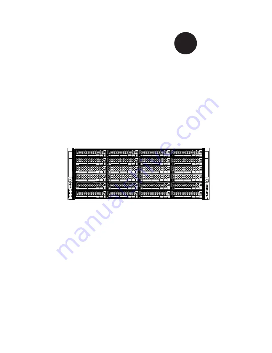
Page 1: ...SC848 CHASSIS SERIES USER S MANUAL 1 0a SUPER SC848A R1800B ...

Page 2: ...ED OR USED WITH THE PRODUCT INCLUDING THE COSTS OF REPAIRING REPLACING INTEGRATING INSTALLING OR RECOVERING SUCH HARDWARE SOFTWARE OR DATA Any disputes arising between manufacturer and customer shall be governed by the laws of Santa Clara County in the State of California USA The State of California County of Santa Clara shall be the exclusive venue for the resolution of any such disputes Super Mi...

Page 3: ... It provides information for the installation and use of the SC848 chassis Installation and maintenance should be performed by experienced technicians only This manual lists compatible parts available when this document was published Al ways refer to the our Web site for updates on supported parts and configurations ...

Page 4: ...r details on this chassis model including the fans bays airflow shields and other components Chapter 4 System Interface Refer to this chapter for details on the system interface which includes the functions and information provided by the control panel on the chassis as well as other LEDs located throughout the system Chapter 5 Chassis Setup and Maintenance Follow the procedures given in this chap...

Page 5: ...your chassis For complete information on supported cables and hardware refer to the Supermico Web site at www supermicro com Appendix B Power Supply Specifications This chapter lists the specifications of the power supplies provided with your chas sis For additional information refer to the Supermicro website at www supermicro com Appendix C SAS 846A Backplane Specifications This section contains ...

Page 6: ...3 2 6 System Safety 2 3 Chapter 3 System Interface 3 1 Overview 3 1 3 2 Control Panel Buttons 3 2 3 3 Control Panel LEDs 3 2 3 4 Drive Carrier LEDs 3 4 SAS SATA Drives 3 4 SCSI Drives 3 4 Chapter 4 Chassis Setup and Maintenance 4 1 Overview 4 1 4 2 Removing the Chassis Cover 4 2 4 3 Installing and Removing Hard Drives 4 3 4 4 Installing the Motherboard 4 6 I O Shield 4 6 Permanent and Optional Sta...

Page 7: ...5 1 5 3 Preparing for Setup 5 1 Choosing a Setup Location 5 1 Rack Precautions 5 2 General Server Precautions 5 2 Rack Mounting Considerations 5 3 Ambient Operating Temperature 5 3 Reduced Airflow 5 3 Mechanical Loading 5 3 Circuit Overloading 5 3 Reliable Ground 5 3 5 4 Rack Mounting Instructions 5 4 Rack Rails Assembly 5 4 Identifying the Inner Rack Rails 5 4 Installing the Inner Rails on the Ch...

Page 8: ...SC848 Chassis Manual viii Notes ...

Page 9: ...pped with three 900 Watt 2 1 redundant for a total of 1800 Watts high efficiency power supplies High performance fans provide ample optimized cooling for FB DIMM memory modules and twenty four hot swappable drive bays offer maximum storage capacity 1 2 Shipping List Part Numbers Please visit the following link for the latest shiping lists and part numbers for your particular chassis model http www...

Page 10: ... To en sure the highest level of professional service and technical support we strongly recommend purchasing exclusively from our Supermicro Authorized Distributors System Integrators Resellers A list of Supermicro Authorized Distributors System Integrators Resellers can be found at http www supermicro com Click the Where to Buy link ...

Page 11: ...ddress Super Micro Computer B V Het Sterrenbeeld 28 5215 ML s Hertogenbosch The Netherlands Tel 31 0 73 6400390 Fax 31 0 73 6416525 Email sales supermicro nl General Information support supermicro nl Technical Support rma supermicro nl Customer Support Asia Pacific Address Super Micro Computer Inc 4F No 232 1 Liancheng Rd Chung Ho 235 Taipei County Taiwan R O C Tel 886 2 8226 3990 Fax 886 2 8226 3...

Page 12: ...must be mailed when service is complete For faster service RMA authorizations may be requested online http www supermicro com support rma Whenever possible repack the chassis in the original Supermicro carton using the original packaging material If these are no longer available be sure to pack the chassis securely using packaging material to surround the chassis so that it does not shift within t...

Page 13: ...is It should be situated in a clean dust free area that is well venilated Avoid areas where heat electrical noise and eletromagnetic fields are generated You will also need it placed near at least one grounded power outlet When config ured the SC848 chassis includes two power supplies which require two grounded outlets 2 3 Preparing for Setup The SC848 chassis includes a set of rail assemblies inc...

Page 14: ...mplete circuit which will cause electrical shock Use extreme caution when using metal tools which can easily damage any electrical components or circuit boards they come into contact with Do not use mats designed to decrease electrostatic discharge as protection from electrical shock Instead use rubber mats that have been specifically designed as electrical insulators The power supply power cord m...

Page 15: ... ensuring that all connections have been made 2 6 System Safety Electrostatic discharge ESD is generated by two objects with different electrical charges coming into contact with each other An electrical discharge is created to neutralize this difference which can damage electronic components and printed circuit boards The following measures are generally sufficient to neutralize this difference b...

Page 16: ...s or contacts When handling chips or modules avoid touching their pins Put the serverboard and peripherals back into their antistatic bags when not in use For grounding purposes make sure your computer chassis provides excellent conductivity between the power supply the case the mounting fasteners and the serverboard ...

Page 17: ...eep you constantly informed of the overall status of the system as well as the activity and health of specific components Most SC848 models have two buttons on the chassis control panel a reset button and a power on off switch This chapter explains the meanings of all LED indicators and the appropriate responses you may need to take Figure 3 1 Front LED Panel ...

Page 18: ...tem Turning off system power with this button removes the main power but keeps standby power supplied to the system Therefore you must unplug system before servicing 3 2 Control Panel Buttons There are two push buttons located on the left handle of the chassis These are in order from top to bottom a power on off button and a reset button Power Indicates power is being supplied to the system s powe...

Page 19: ...n failure When con tinuously on not flashing it indicates an overheat condition which may be caused by cables obstructing the airflow in the system or the ambient room temperature being too warm Check the routing of the cables and make sure all fans are pres ent and operating normally You should also check to make sure that the chassis covers are installed Finally verify that the heatsinks are ins...

Page 20: ...n a solid on state this blue LED on the front of the SAS SATA drive carrier indicates drive activity A connection to the SAS SATA backplane enables this LED to blink on and off when that particular drive is being accessed Red Solid on Drive failure Blinking Rebuilding RAID The red LED to indicate an SAS SATA drive failure If one of the SAS SATA drives fail you should be notified by your system man...

Page 21: ...erence while setting up your chassis Review the warnings and precautions listed in the manual before setting up or servicing this chassis These include information in Chapter 2 System Safety and the warnings precautions listed in the setup instructions Safety Warning Before performing any chassis setup or mainte nance it is recommended that the chassis be removed from the rack and placed on a stab...

Page 22: ...ce the top cover is released from the locked position slide the cover 2 toward the rear of the chassis Lift the cover off the chassis 3 Warning Except for short periods of time do NOT operate the server without the cover in place The chassis cover must be in place to allow proper airflow and prevent overheating Figure 4 1 Removing the Chassis Cover Remove this screw If necessary 1 1 2 3 ...

Page 23: ...3 Installing and Removing Hard Drives Removing Hard Drive Trays from the Chassis Press the release button on the drive tray This extends the drive bay handle 1 Use the handle to pull the drive out of the chassis 2 Figure 4 2 Removing Hard Drive 2 1 ...

Page 24: ...ve Tray Installing a Hard Drive to the Hard Drive Tray Remove the two screws securing the dummy drive to the drive tray and 1 remove the dummy drive Place the hard drive tray on a flat surface such as a desk table or work bench Warning Except for short periods of time swapping hard drives do not operate the server with the hard drives empty Figure 4 4 Removing Dummy Drive from Tray Drive Tray Dumm...

Page 25: ...ounting holes in both the drive tray and the hard drive 3 Secure the hard drive to the tray using six screws 4 Replace the drive tray into the chassis Make sure to close the drive tray 5 handle to lock the drive tray into place Drive Tray SAS SATA Hard Drive Figure 4 5 Installing the Hard Drive into the Tray Figure 4 6 Installing the Hard Drive 4 4 5 ...

Page 26: ...lling the I O Shield Review the documentation that came with your motherboard Become familiar 1 with component placement requirements and precautions Open the chassis cover 2 With the illustrations facing the outside of the chassis place the shield into 3 the space provided Once installed the motherboard will hold the I O shield in place 4 I O Shield Figure 4 7 I O Shield Placement ...

Page 27: ...urface The SC848 chassis includes permanent standoffs in locations used by most motherboards These standoffs are included in the SC848 acces sories packaging Some motherboards require additional screws for heatsinks general components and or non standard security Optional standoffs are included to these mother boards To use an optional standoff you must place the standoff through the bottom the ch...

Page 28: ...xagonal standoff through the bottom the chassis and tighten the standoff with a wrench Lay the motherboard on the chassis aligning the permanent and optional 4 standoffs Secure the motherboard to the chassis using the rounded Phillips head 5 screws CAUTION Do not exceed 8 lbs of torque when tightening the screws Figure 4 10 Motherboard Installation ...

Page 29: ... the motherboard backplane chassis front 7 panel and power supply as needed See the Routing Cables in the Pe ripheral Drawer section of this manual for details on routing cabling to the peripheral drawer Carefully slide the middle bracket back into the chassis routing the mother 8 board cables through the rubber gateway at the bottom of the middle bracket Connect the fan cables to the motherboard ...

Page 30: ...ks may be required on the SC848 motherboard The installation process of these heatsinks may vary with different motherboards Typically heatsinks will clip onto the motherboard and may be installed without removing the motherboard Check the documentation that came with your motherboard for specific instructions on how to install heatsinks ...

Page 31: ...ds Installing Add on and Expansion Cards in the SC848 Chassis Disconnect the power supply lay the chassis on a flat surface and open the 1 chassis cover Remove the screw holding the cover in place for each add on expansion card 2 slot you want to use Keep this screw for later use Connect the add on cards and or expansion cards to the mother board 3 4 Secure each card to the chassis using the card ...

Page 32: ...ad motherboard MCP 310 84802 0B Mylar air shroud for AMD H8 Quad motherboard Before installing the AMD airshroud 16 DIMM Remove all pieces marked 32 DIMM and the outer left side piece 32 DIMM Remove all pieces marked 16 DIMM and the inner left side piece Figure 4 14 Air Shroud for SC848 Chassis Figure 4 15 Adapting the Air Shroud for AMD Motherboards 32 DIMM AMD MB Remove Inner Side and Pieces Mar...

Page 33: ... front bezel make sure the bezel s filter is replaced periodically 2 Do not operate the server without drives or drive trays in the drive bays Use only recommended server parts 3 Make sure no wires or foreign objects obstruct air flow through the chassis Pull all excess cabling out of the airflow path or use shorter cables The control panel LEDs inform you of system status See Chapter 3 System Int...

Page 34: ...r an extended period of time with the chassis open Turn off the power to the system and unplug the system from the outlet 2 Press the fan release tab to lift the failed fan from the chassis and pull it 3 completely from the chassis Place the new fan into the vacant space in the housing while making sure the 4 arrows on the top of the fan indicating air direction point in the same direc tion as the...

Page 35: ...4 15 Chapter 4 Chassis Setup and Maintenance Figure 4 18 Installing a Front System Fan ...

Page 36: ... supply is operating Redundant power supplies are hot swappable and can be changed without power ing down the system New units can be ordered directly from Supermicro see the contact information in the Preface of this manual Changing the Power Supply The SC848 chassis includes redundant 2 1 power supply modules Any one 1 of the three power supply modules may be removed and replaced without having ...

Page 37: ...ver Replace the failed power module with the same model or use a dummy 4 cover if power redundancy is not required Push the new power supply module or dummy cover into the power bay until 5 it clicks into the locked position Figure 4 20 Installing the Power Supply and Dummy Cover ...

Page 38: ...nd remove the plug from the wall socket or power 1 strip Unplug the fan cables from the motherboard and then remove the middle 2 bracket See page 4 7 Remove all cable connections to the power distributor board from the mother 3 board backplane and other components Also remove both power supplies Locate the power distributor board between the power supply and the back 4 plane Remove the three screw...

Page 39: ...to the pins in the floor of the chassis lower the board over the pins then slide it forward into the locked position Align the holes of the power distributor board wth standoffs in the chassis 9 Note that two of these holes are slotted thru holes designed to allow for the board to be adjusted Secure the board to the chassis following the lettered A B C D sequence 10 shown below Figure 4 23 Power D...

Page 40: ...tor cables out the top of the power distributor board cover and leave the 4 pin connector aside for peripheral use Reconnect all the power cables Spread the power cables to the motherboard 12 carefully before replacing the middle bracket Make sure the wires passing through the rubber gates of the bracket are not being squeezed Replace the power supplies and insert the plug into the wall 13 Figure ...

Page 41: ... 5 HDD MCP 220 00044 0N MCP 220 00048 0N Needed 3 Dummy Cover MCP 290 11101 0B 4 Slim USB MCP 220 00065 0B 5 Slim 2 5 HDD MCP 220 00066 0B 6 Slim FDD MCP 220 00067 0B 7 Slim DVD MCP 220 00068 0N Location Peripheral Device Position A Position B N A Default or 1 or 2 N A Default or 1 or 2 Position C Position D 3 Default or 4 or 5 or 6 or 7 3 Default or 4 or 5 or 6 or 7 Dummy Cover Slim USB Slim 2 5 ...

Page 42: ...s Including the motherboard and the power distributor board Using the left hand press the peripheral drawer release button A with the 4 thumb while simultaneously using the other fingers to push the back of the peripheral drawer forward in the peripheral drawer slot and out of the chas sis 1 A Figure 4 26 Peripheral Drawer Release Button Figure 4 27 Removing the Peripheral Drawer CAUTION Cable len...

Page 43: ... them into the bracket with eight round head screws as illustrated then secure the bracket into the tray using four flat head screws as shown Secure the drive tray into the floor of the peripheral drawer using two screws 2 as shown on the following page of this manual Connect the cables to the drives 3 Figure 4 28 Installing One 3 5 HDD into the HDD Tray Figure 4 29 Installing Two 2 5 HDDs into th...

Page 44: ...SC848 Chassis Manual 4 24 Figure 4 31 Installing 2 5 HDDs into the Peripheral Drawer Figure 4 30 Installing 3 5 HDDs into the Peripheral Drawer ...

Page 45: ...g Peripheral Devices into the Peripheral Drawer Installing Peripheral Devices in the Peripheral Drawer Installing Peripheral Devices Remove the dummy covers from the front of the peripheral device bays on 1 the front of the peripheral drawer Install the peripheral devices into the peripheral device bays 2 ...

Page 46: ...oving Peripheral Devices Press the release latch on the back of the peripheral device bay towards the 1 wall of the chassis Figure 4 34 Peripheral Device Release Latches Figure 4 35 Removing Peripheral Devices Press the back of the peripheral device gently pushing it forward out the front 2 of the peripheral device bay ...

Page 47: ...into the chassis while simultaneously pulling the 3 cables which lead to the drawer without breaking or disconnecting the cables until the drawer clicks into the locked position Use zip ties to bundle the cables where indicated in the diagram below 4 Connect the power cable to the 4 pin peripheral connector from the power 5 distributor board Route the signal cable over the top of the power distrib...

Page 48: ... backplane from the chassis Removing the Backplane Power down and unplug the system from any power source 1 Pull all of the existing hot swappable hard drives half way out of their drive 2 bays in the front of the chassis Disconnect the cabling to the backplane 3 Remove the four upper screws securing backplane housing to the chassis 4 and set these aside for later use 1 4 Figure 4 37 Removing the ...

Page 49: ... the Chassis 7 Gently lift the Backplane From the Chassis Remove the five lower screws securing the backplane housing to the chassis 5 floor and set these aside for later use Remove the two side screws on the right side of the chassis 6 Gently ease the backplane up and out of the chassis 7 Remove Five Lower Screws Remove Two Side Screws ...

Page 50: ...into position in the chassis 2 Replace the five lower screws which secure the backplane housing to the 3 chassis floor Replace the two side screws 4 2 Slide the Backplane into the Chassis Replace the Five Lower Screws Figure 4 40 Replacing the Backplane in the Chassis Figure 4 41 Replacing the Lower and Side Screws 3 1 4 Remove Two Side Screws ...

Page 51: ...s Setup and Maintenance Replace the four upper screws which secure the backplane housing to the 5 chassis Reconnect all cabling to the backplane 6 Replace the Four Upper Screws 5 Figure 4 42 Replacing the Four Upper Screws ...

Page 52: ...SC848 Chassis Manual 4 32 Notes ...

Page 53: ...ree area that is well ventilated Avoid areas where heat electrical noise and electromagnetic fields are generated You will also need it placed near a grounded power outlet Be sure to read the Rack and Server Pre cautions in the next section 5 3 Preparing for Setup The box your chassis was shipped in should include one pair of rail assemblies two rail mounting brackets and the mounting screws you w...

Page 54: ...on stabilizers should be attached to the rack In multiple rack installations the racks should be coupled together Always make sure the rack is stable before extending a component from the rack You should extend only one component at a time extending two or more si multaneously may cause the rack to become unstable General Server Precautions Review the electrical and general safety precautions that...

Page 55: ...quipment should be mounted into a rack so that the amount of airflow required for safe operation is not compromised Mechanical Loading Equipment should be mounted into a rack so that a hazardous condition does not arise due to uneven mechanical loading Circuit Overloading Consideration should be given to the connection of the equipment to the power supply circuitry and the effect that any possible...

Page 56: ...will differ slightly You should also refer to the installation instructions that came with the rack unit you are using NOTE This rail will fit a rack between 27 to 34 45 deep Identifying the Inner Rack Rails The chassis package includes one pair of rack rail assemblies in the rack mounting kit Each assembly consists of an inner rail that secures to the chassis and an outer rail that is attached di...

Page 57: ...nner rail on the side of the chassis aligning the hooks of the chassis with the inner rail holes Make sure the rail faces outward so that it will fit with the rack s mounting bracket Slide the rail toward the front of the chassis to hook the inner rail onto the 2 side of the chassis Secure the chassis with two flat head M4 x 4mm screws as illustrated 3 Repeat steps 1 3 for the other inner rack rai...

Page 58: ... the proper distance so that the rail 2 fits snugly into the rack Secure the long bracket to the front side of the outer rail with two M5 screws 3 and washers and the short bracket to the rear side of the outer rail with three M5 screws and washers Keep the screws slack so that they may be adjusted later Repeat steps 1 4 for the left outer rail 4 Secure to the Front of the Rack Secure to the Rear ...

Page 59: ...5 7 Chapter 5 Rack Installation Screws and Washers Screws and Washers Figure 5 4 Installing the Outer Rails to the Rack 3 2 ...

Page 60: ...ck rails B 2 Slide the chassis rails into the rack rails keeping the pressure even on both 3 sides you may have to depress the locking tabs when inserting When the server has been pushed completely into the rack you should hear the locking tabs click into the locked position Tighten up all the screws on the front side and rear side of both outer rails 4 Optional Insert and tightening the thumbscre...

Page 61: ...e chassis when removing it from the rack Removing the Chassis from the Rack Pull the chassis forward out the front of the rack until it stops 1 Press both of the black plastic release latches on each of the inner rails 2 downward simultaneously and move the chassis forward in the rack When the chassis stops a second time press both of the black plastic release 3 latches on the rear of the inner ra...

Page 62: ...SC848 Chassis Manual 5 10 Notes ...

Page 63: ...w supermicro com A 2 Cables Included with SC848A Chassis SAS SATA SC848A R1800 Part Type Length Description CBL 0084L Cable 6 Front control cable 16 pin split convertor CBL 0087 Ribbon Round 20 16 pin to 16 pin ribbon cable for control panel CBL 0088L Cable 10 5 4 pin middle fan power extension PWM CBL 0216L Cable 7 87 4 to 4 pin middle fan power exten sion PWM CBL 0160L Cable US power cord 16AWG ...

Page 64: ... 0175L Alt Name Big Four Alternate SAS SATA Cables Some compatible motherboards have different connectors If your motherboard has only one SAS connector that the SAS SATA cables must share use one of the following cables These cables must be purchased separately Description This cable has one ipass SFF 8087 mini sas connector 36 pins at one end and 4 SAS connectors on one end This cable connects f...

Page 65: ...0 pin CBL 0059 7 9 20 CM 8 pin CBL 0062 7 9 20 CM 4 pin CBL 0060 7 9 20 CM Front Panel to the Motherboard The SC848 chassis includes a cable to connect the chassis front panel to the motherboard If your motherboard uses a different connector use the following list to find a compatible cable Front Panel to Motherboard Cable Ribbon Cable Number of Pins Front Panel Number of Pins Motherboard Cable Pa...

Page 66: ...0 157 RAIL Round head M4 x 4 mm 0 157 Flat head M5 x 12 mm 0 472 Washer for M5 DVD ROM CD ROM and FLOPPY DRIVE Flat head 6 32 x 5 mm 0 197 Pan head 6 32 x 5 mm 0 197 Round head M3 x 5 mm 0 197 Pan head 6 32 x 5 mm 0 197 M B Flat head 6 32 x 5 mm 0 197 HARD DRIVE Thumb screw 6 32 x 5 mm 0 197 M B standoff 6 32 to 6 32 M B standoff M5 to 6 32 M B STANDOFFS M B CPU standoff M5 to 6 32 Round head M2 6...

Page 67: ...power supply specifications for your chassis system SC848TQ R1800B 900W 2 1 for a total of 1800W MFR Part PWS 902 1R Rated AC Volt age 100 240V 60 50Hz 11 4 5 Amp 5V standby 4 Amp 12V 75 Amp 5V 50 Amp 3 3V 30 Amp 12V 0 6 Amp For ordering purposes the part number of the power supply dummy cover is CSE PT0130L ...

Page 68: ...SC848 Chassis Manual B 2 Notes ...

Page 69: ...o prevent static discharge Touch a grounded metal object before removing a component from the antistatic bag Handle the RAID card by its edges only do not touch its components peripheral chips memory modules or gold contacts When handling chips or modules avoid touching their pins Put the card and peripherals back into their antistatic bags when not in use C 2 General Safety Guidelines Always disc...

Page 70: ...own in this manual C 4 Introduction to the SAS 846A Backplane The SAS 846A backplane has been designed to utilize the most up to date technol ogy available providing your system with reliable high quality performance This manual reflects SAS 846A Revision 1 00 the most current release available at the time of publication Always refer to the Supermicro Web site at www supermicro com for the latest ...

Page 71: ...3 NO RESET 1 2 RESET 22 23 20 21 18 19 16 17 14 15 12 13 10 11 8 9 6 7 4 5 3 2 1 0 JP129 9072 3 RESET JP35 9072 1 RESET JP50 9072 2 RESET BUZZER RESET 2 3 NO FAN 1 2 WITH FAN JP61 FAN 1 SELECT JP64 FAN 4 SELECT JP63 FAN 3 SELECT JP62 FAN 2 SELECT 2 3 NO FAN 1 2 WITH FAN JP97 FAN 1 SELECT JP98 FAN 2 SELECT JP99 FAN 3 SELECT JP100 FAN 4 SELECT C C C OPEN 45 1 2 50 2 3 55 JP107 OH 3 TEMP ACT_IN 16 23...

Page 72: ...n the front panel For the Activity LED Header to work properly connect using a 10 pin LED cable 4 5 6 I2 C Connectors The I2 C Connectors designated JP37 JP95 JP52 JP96 JP116 and JP117 are used to monitor HDD activity and status See the table on the right for pin definitions I2 C Connector Pin Definitions JP37 JP95 JP52 JP96 JP116 and JP117 Pin Definition 1 Data 2 Ground 3 Clock 4 No Connection Ba...

Page 73: ...D49 A C D47 A C D45 A C D89 A C C85 C84 C5 C45 C44 C3 C204 C203 C202 C201 C200 C199 C198 C197 C119 C285 C330 C329 C328 C327 C326 C325 C324 C323 C283 C229 C20 C193 C19 C173 C318 1 16 49 64 U73 U40 U19 I2C 2 CH 20 23 CH 12 15 CH 8 11 CH 4 7 2 3 I2C 1 2 SGPIO JP84 MODE 2 3 NO RESET 1 2 RESET 2 3 NO RESET 1 2 RESET 2 3 NO RESET 1 2 RESET 22 23 20 21 18 19 16 17 14 15 12 13 10 11 8 9 6 7 4 5 3 2 1 0 JP...

Page 74: ...fault 2 3 No Fan FAN 2 JP63 1 2 With Fan Default 2 3 No Fan FAN 3 JP99 1 2 With Fan Default 2 3 No Fan FAN 3 JP64 1 2 With Fan Default 2 3 No Fan FAN 4 JP100 1 2 With Fan Default 2 3 No Fan FAN 4 I2 C and SGPIO Modes and Jumper Settings This backplane can utilize I2 C or SGPIO SGPIO is the default mode and can be used without making changes to your jumper The following information details which ju...

Page 75: ... C D53 A C D36 A C D3 A C D51 A C D49 A C D47 A C D45 A C D89 A C C85 C84 C5 C45 C44 C3 C204 C203 C202 C201 C200 C199 C198 C197 C119 C285 C330 C329 C328 C327 C326 C325 C324 C323 C283 C229 C20 C193 C19 C173 C318 1 16 49 64 U73 U40 U19 I2C 2 CH 20 23 CH 12 15 CH 8 11 CH 4 7 2 3 I2C 1 2 SGPIO JP84 MODE 2 3 NO RESET 1 2 RESET 2 3 NO RESET 1 2 RESET 2 3 NO RESET 1 2 RESET 22 23 20 21 18 19 16 17 14 15 ...

Page 76: ...7 6 3 2 1 0 SAS SAS SAS SAS SAS SAS SAS SAS SAS SAS SAS SAS SAS SAS SAS SAS FAIL 12 ACT 12 ACT 8 FAIL 8 ACT 4 FAIL 4 ACT 0 FAIL 0 C 8 Rear Connectors and LED Indicators Rear SAS SATA Connectors Rear Connector SAS Drive Number Rear Connector SAS Drive Number SAS 0 SAS SATA HDD 1 SAS 12 SAS SATA HDD 13 SAS 1 SAS SATA HDD 2 SAS 13 SAS SATA HDD 14 SAS 2 SAS SATA HDD 3 SAS 14 SAS SATA HDD 15 SAS 3 SAS ...

Page 77: ... SAS 2 D14 D7 SAS 3 D15 D8 SAS 4 D18 D19 SAS 5 D21 D20 SAS 6 D22 D23 SAS 7 D24 D29 SAS 8 D25 D30 SAS 9 D26 D31 SAS 10 D27 D32 SAS 11 D28 D33 SAS 12 D40 D37 SAS 13 D41 D38 SAS 14 D42 D39 SAS 15 D87 D88 SAS 16 D100 D103 SAS 17 D101 D105 SAS 18 D102 D107 SAS 19 D104 D108 SAS 20 D106 D109 SAS 21 D111 D110 SAS 22 D118 D119 SAS 23 D120 D121 ...

Page 78: ... reasonably expected to result in significant injury or loss of life or catastrophic property damage Accordingly Supermicro disclaims any and all liability and should buyer use or sell such products for use in such ultra hazardous applications it does so entirely at its own risk Furthermore buyer agrees to fully indemnify defend and hold Supermicro harmless for and against any and all claims deman...

Reviews: