Supermicro Supero SC513 Series, User Manual
The Supermicro Supero SC513 Series is an exceptional product designed to meet your server needs efficiently. With its compact design and superior performance, this device guarantees reliability and productivity. Unlock its full potential by accessing the comprehensive User Manual, available for free download from 88.208.23.73:8080.
Share
Download

Reviews:
No comments
Related manuals for Supero SC513 Series

DA-4PM/0F2
Brand: Optimus Pages: 36

XACT PRO 7448
Brand: WP Pages: 30
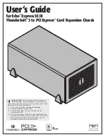
Echo Express SE III
Brand: Sonnet Pages: 14
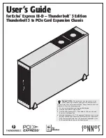
Echo Express III-D Thunderbolt 3 Edition
Brand: Sonnet Pages: 14
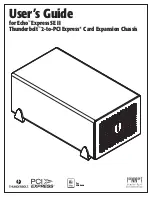
echo express SE II
Brand: Sonnet Pages: 16
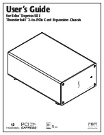
Echo Express SE I
Brand: Sonnet Pages: 16

OV-MCR116
Brand: AirLive Pages: 12

PXI Express PXIe-1071
Brand: National Instruments Pages: 65

FastIron SX 1600
Brand: Brocade Communications Systems Pages: 216

NI 9144
Brand: National Instruments Pages: 95

X-Sniper
Brand: Apevia Pages: 13

X-Jupiter
Brand: Apevia Pages: 12
NVR 2U
Brand: Digiop Pages: 4


