background image

Rev. 1.0

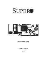
AOC-USASLP-L8i 

USER'S GUIDE

LED1LE

D

1

LED2L

E

D

2

DESIGNED IN USA

DESIGNED IN USA

AOC-USASLP-L8i

AOC-USASLP-L8i

WWNW

W

N

BAR CODE

BAR CODE

SAS 4-7S

A

S

 4

-7

SAS 0-3S

A

S

 0

-3

LED2: HEARTBEAT & FAULT

LED2: HEARTBEAT & FAULT

LED1: ACTIVITY

LED1: ACTIVITY

SAS INTERNAL

SAS INTERNAL


S

UPER

®

Summary of Contents for AOC-USASLP-L8i

Page 1: ...1 LED1 LED2 LED2 DESIGNED IN USA DESIGNED IN USA AOC USASLP L8i AOC USASLP L8i WWN WWN BAR CODE BAR CODE SAS 4 7 SAS 4 7 SAS 0 3 SAS 0 3 LED2 HEARTBEAT FAULT LED2 HEARTBEAT FAULT LED1 ACTIVITY LED1 AC...

Page 2: ...RODUCT OR DOCUMENTATION EVEN IF ADVISED OF THE POSSIBILITY OF SUCH DAMAGES IN PARTICULAR SUPERMICRO SHALL NOT HAVE LIABILITY FOR ANY HARDWARE SOFTWARE OR DATA STORED OR USED WITH THE PRODUCT INCLUDING...

Page 3: ...ting Supermicro v Chapter 1 Safety Guidelines 1 1 ESD Safety Guidelines 1 1 1 2 General Safety Guidelines 1 1 1 3 An Important Note to Users 1 2 Chapter 2 LED Indicators and Connectors 2 1 Front Conne...

Page 4: ...rm factor Internal and external iPass cable ports LED heartbeat and fault indicator Operating Systems Supported AOC USASLP L8i add on card supports the following Operating Systems OS Windows 2000 Wind...

Page 5: ...dress Super Micro Computer B V Het Sterrenbeeld 28 5215 ML s Hertogenbosch The Netherlands Tel 31 0 73 6400390 Fax 31 0 73 6416525 Email sales supermicro nl General Information support supermicro nl T...

Page 6: ...esigned to prevent static discharge Touch a grounded metal object before removing a component from the antistatic bag Handle the card by its edges only do not touch its components peripheral chips mem...

Page 7: ...nt Note to Users All images and layouts shown in this user s guide are based upon the latest PCB Revision available at the time of publishing The card you have received may or may not look exactly the...

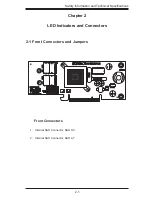
Page 8: ...SASLP L8i WWN WWN BAR CODE BAR CODE SAS 4 7 SAS 4 7 SAS 0 3 SAS 0 3 LED2 HEARTBEAT FAULT LED2 HEARTBEAT FAULT LED1 ACTIVITY LED1 ACTIVITY SAS INTERNAL SAS INTERNAL Chapter 2 LED Indicators and Connect...

Page 9: ...1 Internal SAS Connector The internal SAS ports J3 and J4 connect to the backplane allowing the motherboard to access the hard drives and RAID capabilities This connector supports up to 4 HDD ports Us...

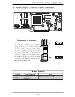
Page 10: ...De nitions Jumper Settings Jumper Jumper Settings Note 3 SWR5 1 2 Enabled 3 Disabled Enables or disables SWR5 Explanation of Jumpers To modify the operation of the backplane jumpers can be used to cho...

Page 11: ...ing Heartbeat and Fault LED Indicators LED1 LED1 LED2 LED2 DESIGNED IN USA DESIGNED IN USA AOC USASLP L8i AOC USASLP L8i WWN WWN BAR CODE BAR CODE SAS 4 7 SAS 4 7 SAS 0 3 SAS 0 3 LED2 HEARTBEAT FAULT...

Reviews: