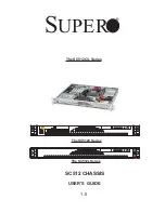
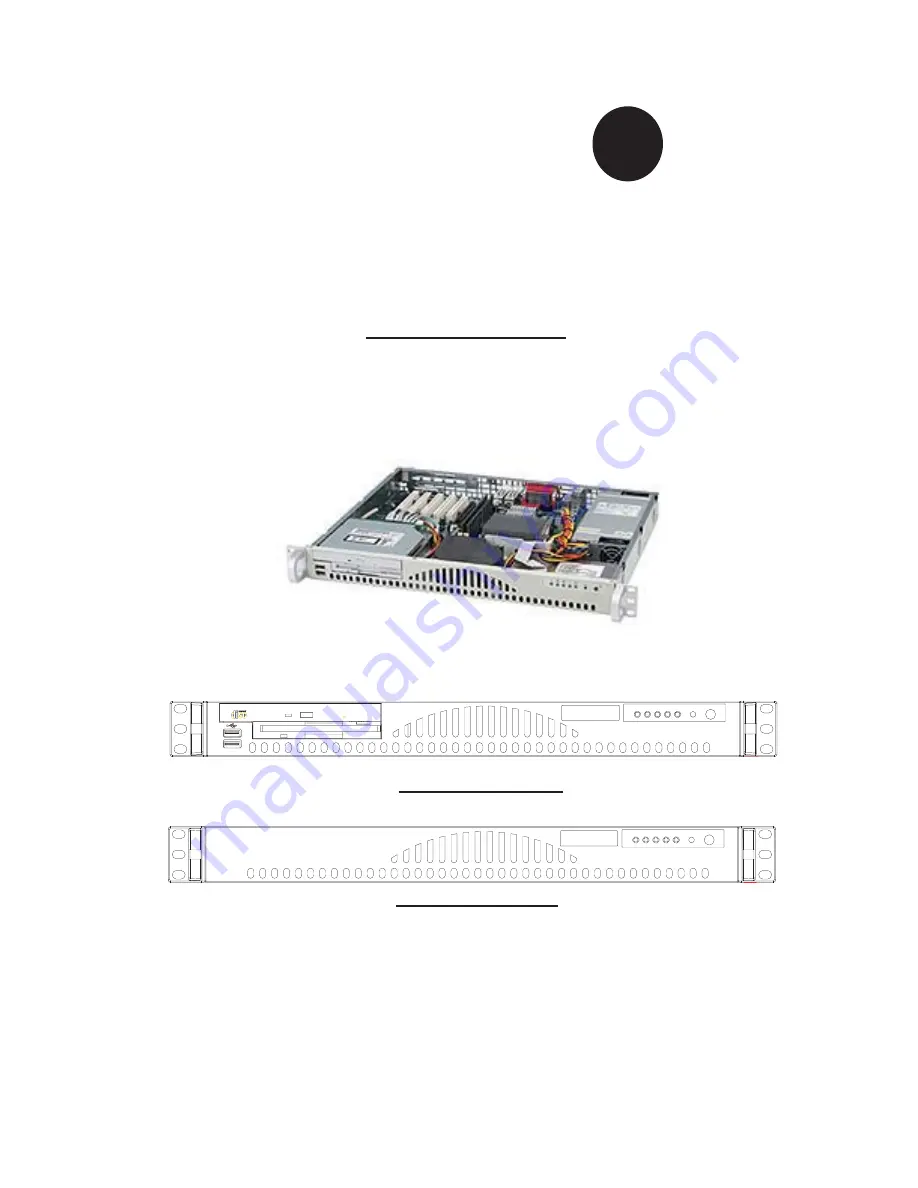
background image

1.0

®


S

UPER

SC512 CHASSIS

   USER'S  GUIDE

The SC512C/L Series

The SC512C Series

The SC512L Series

Summary of Contents for SC512C Series

Page 1: ...1 0 SUPER SC512 CHASSIS USER S GUIDE The SC512C L Series The SC512C Series The SC512L Series ...

Page 2: ...USE THIS PRODUCT OR DOCUMENTATION EVEN IF ADVISED OF THE POSSIBILITY OF SUCH DAMAGES IN PARTICULAR THE VENDOR SHALL NOT HAVE LIABILITY FOR ANY HARDWARE SOFTWARE OR DATA STORED OR USED WITH THE PRODUCT INCLUDING THE COSTS OF REPAIRING REPLACING INTEGRATING INSTALLING OR RECOVERING SUCH HARDWARE SOFTWARE OR DATA Any disputes arising between manufacturer and customer shall be governed by the laws of ...

Page 3: ...rocedures 2 1 2 1 Chassis Description 2 1 A Contents of the Accessory Kit 2 1 B Power Cords SATA Cables 2 1 C Chassis Front View and the Front Control Panel 2 2 D Chassis Rear View and the Back Panel 2 3 2 2 Chassis Installation 2 4 A Important Safety Guidelines 2 4 B Tools Needed 2 4 C Removing the Top Chassis Cover and the HDD Tray Bracket 2 5 D1 Removing the CD ROM Module 2 6 D2 Removing the HD...

Page 4: ...printed circuit boards PCBs in their antistatic bags until ready for use Touch a grounded metal object before removing chassis components or the motherboard from the antistatic bag Do not let components or PCBs come into contact with your clothing which may retain a charge even if you are wearing a wrist strap Handle a motherboard by its edges only do not touch its components peripheral chips memo...

Page 5: ...ose parts screws inside the chassis 2 Make sure that all cables are properly connected to the connectors and ports 3 Use the original screws or fasteners to install the covers to the chassis 4 Be sure to lock to the chassis or the system to prevent unauthorized access 5 Please follow the procedures listed in Chapter 2 to install or remove components to or from the SC512 1 5 An Important Note to th...

Page 6: ...the following safety standards requirements Product Safety Canada USA UL60 950 CSA60 950 European Union EN 60 950 International IEC 60 950 Power Supply only Electromagnetic Compatibility EMC Emissions European Union EN55022 1994 International CISPR 22 USA Title 47 CFR Part 15 Power Line Harmonics Voltage Flicker European Union EN61000 3 2 EN61000 3 3 Electromagnetic Compatibility Immunity European...

Page 7: ...Part Number Blower One 5000rpm blower FAN 0059 HDD Two 3 5 Drives USB N A Floppy N A CD ROM N A Power 260W PWS 0055 The SC512C Series Component Qty Part Number Blower One 3800rpm blower FAN 0038 HDD One 3 5 Drive USB One 2 0 Connection Floppy One Slim FDD FPD MISMI 02 CD ROM One Slim CD ROM CDM TEAC 24 Power 200W PWS 0043 The SC512C 260 Series Component Qty Part Number Blower One 5000rpm blower FA...

Page 8: ...ns Form Factor 14 mini 1U chassis support for maximum MB size 12 x9 7 304 7mmx 246 4mm ATX CPU Support Pentium 4 Expansion Card One full height half length PCI Slot w Riser Card Drive Bays The SC512L Series two 3 5 fixed the SC512C Series one 3 5 fixed Cooling System One 10cm blower 200W 3800rpm 260W 5000rpm Front Panel LEDs One PWR LED one HDD Activity LED two Network Interface LEDs one System Ov...

Page 9: ... 197 Taper head 6 32 x 5 mm 0 197 A A Pan head w lock 6 32 x 4 5 mm 0 177 Pan head w lock 6 32 x 4 5 mm 0 177 M B M B B B B Flat head 6 32 x 5 mm 0 197 Flat head 6 32 x 5 mm 0 197 HDD C C Thu For 2 5 HDD For 2 5 HDD Hexagon head 6 32 x 5 mm 0 197 Hexagon head 6 32 x 5 mm 0 197 J J Handle Handle For 3 5 HDD For 3 5 HDD J A 2 1 Chassis Description A Contents of the Accessory Kit The following items ...

Page 10: ... OLQN FWLYLW 2II 1R FWLYLW UHHQ 2Q LQNHG OLQN 1 FWLYLW 1 1 2II LVFRQQHFWHG 5HG 2Q 6 VWHP 2YHUKHDW 2YHUKHDW 2II 6 VWHP 1RUPDO C Chassis Front View and the Front Control Panel 1 Front Panel LED Indicators 2 I O Devices SC512C 1 CD ROM and 1 HDD SC512L 1 CD ROM only 3 USB ports x2 2 Front Panel LED Button Definitions 1 Front Panel and I O Device Definitions The SC512C Chassis Front View 1 2 1 The SC512...

Page 11: ...2 3 Chapter 2 Chassis Description and Installation Instructions D Chassis Rear View SC512 Chassis Rear View B 1 2 3 1 Back Panel and I O Device Descriptions 1 Power Connector 2 COM Port 3 LAN Ports ...

Page 12: ... 2 Unplug all power cords from the system or the wall outlets 3 Disconnect all the cables and label the cables for easy identification 4 Use a grounded wrist strap designed to prevent static discharge when handling components Removing the chassis covers After completing the above steps you can remove the chassis covers and install components and devices into the chassis as described in this chapter...

Page 13: ...g a hard drive into the chassis you need to remove the top cover and the HDD tray bracket from the chassis Note Removing the top cover when the system is running will degrade thermal perfor mance Procedures 1 Press the two tabs on the top cover to release the cover from the locking position 2 Once the top cover is loosened slide it out of the chassis 1 2 ...

Page 14: ... the CD ROM module you need to remove the CD ROM module from the chassis Procedures 1 Remove the screw 2 Once the screw is removed slide the CD ROM module toward the backplane to loosen it as shown in the picture below 1 2 3 Once the module is loosened remove it from the SC512 as shown below 3 ...

Page 15: ...sing and Installing the HDDs After the HDD Drive Tray Bracket is removed from the chassis you can install HDDs into the HDD Drive Housing Procedures 1 Remove the four screws on the back of the chassis as shown in the picture 2 Once the screws are removed you can remove the HDD tray from the chas sis ...

Page 16: ...n the reverse side of the CPU Ignore this step if you have a DP sys tem 3 Lay the motherboard on the standoffs and secure it with Mylar sheets if any to the chassis with type A screws 4 Secure CPU heatsink s to the motherboard Refer to the next section for heatsink installation 5 Install the air shroud s on the motherboard by inserting air shroud clips into the corresponding holes 3 4 Note the CPU...

Page 17: ... with care Note Be sure to use Heatsink SNK P0011 for a UP system and use Heatsink SNK P0007 for a DP System Screw 1 Screw 2 Screw 3 Screw 4 1 Unscrew and remove the heatsink screws from the motherboard in the sequence as show in the fourth picture on the right 2 Hold the heatsink as show in the first picture on the right and gently wiggle the heatsink to loosen it from the CPU Do not use excessive...

Page 18: ...their corresponding pins on the chassis install the fan module into the chassis by inserting the holes to the corresponding pins To remove the fan module from the chassis carefully pull the fan module from the chassis Procedures Installing the Air Shroud After the fan module has been properly installed in the chassis you will need to install the air shroud for proper cooling 4 Locate the two holes...

Page 19: ...all the safety steps listed below Procedures to Install Chassis Rails 2 Press the locking tab to release the inner rail from its locking position and pull out the inner rail from the rail assembly The inner rails are to be attached to the chassis and the outer rails are to be installed in the rack Outer rail to be installed in the rack Pull out the Inner rail to be attached on the chassis 1 Includ...

Page 20: ...s on each of the inner rail 4 Attach an inner rail to each side of the chassis and secure the inner rail to the chassis by inserting three Type G screws through the holes on each side of the chassis and the inner rail Refer to Page 2 1 for the Type G screw 5 Repeat the above steps to install the other rail on the chassis G 3 ...

Page 21: ... Arrows front and Up Rear ar rows rear 2 Secure the front short bracket marked with the Up Front arrows to the outer rail with two Type G screws 3 Attach the rear long bracket to the other end of the outer rail and secure the rear long bracket to the outer rail with a Type G screw as shown below 4 Measure the depth of your rack and adjust the length of the rails accordingly 5 Repeat the same steps...

Page 22: ...512 may not slide into the rack smoothly or easily when installed the first time Some adjustment to the slide assemblies might be needed for easy instal lation 8 You will need to release the safety taps on both sides of the chassis in order to completely remove the chassis out of the rack 7a 7b ...

Page 23: ...ls of rail assemblies to the rack The rails are designed to fit in the racks with the depth of 28 to 33 Procedures 1 In the package locate a pair of front short and rear long brackets Please note that the brackets are marked with Up Front Arrows front and Up Rear ar rows rear 2 Secure the front short bracket marked with the Up Front arrows to the outer rail with two Type G screws as shown below G 2...

Page 24: ... it to the rack with two Type H screws and Type I washers as shown below 4 Attach the rear long bracket to the rear end of the rack and secure it to the rack with two Type H screws and Type I washers as shown below Repeat the same steps to install the other outer rail to the other side of rack 4 3 I H H I ...

Page 25: ...ion Instructions 5 Measure the depth of your rack and adjust the length of the rails accordingly Then secure the rails to the chassis with Type G screws 6 Slide the inner rails which are attached to the chassis into the outer rails on the rack 6 5 G ...

Page 26: ...e that all the com ponents are securely fastened to the chassis to prevent components falling off from the chassis 4 The rack assembly shall be properly grounded to avoid electric shock 5 The rack assembly must provide sufficient airflow to the chassis for proper cooling 6 Please make sure that all components and all chassis covers are properly installed in the chassis before you install the SC512 i...

Reviews: