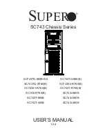
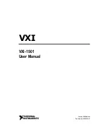
background image

SC743 Chassis Series

SC743TQ-865B-SQ

SC743TQ-865(B)

SC743TQ-R760(B)

SC743S2-R760(B)

SC743S1-R760(B)

SC743T-R760(B)

SC743i-R760(B)

SC743i-665B

SC743T-665B

SC743i-500B

SC743T-500B

SC743i-465B

USER’S MANUAL

1.2d


S

UPER

®

Summary of Contents for SC743i-465B

Page 1: ...3 Chassis Series SC743TQ 865B SQ SC743TQ 865 B SC743TQ R760 B SC743S2 R760 B SC743S1 R760 B SC743T R760 B SC743i R760 B SC743i 665B SC743T 665B SC743i 500B SC743T 500B SC743i 465B USER S MANUAL 1 2d S...

Page 2: ...WARE SOFTWARE OR DATA STORED OR USED WITH THE PRODUCT INCLUDING THE COSTS OF REPAIRING REPLACING INTEGRATING INSTALLING OR RECOVERING SUCH HARDWARE SOFTWARE OR DATA Any disputes arising between manufa...

Page 3: ...should be performed by experienced technicians only Supermicro s SC743 chassis features a unique and highly optimized design The chassis is equipped with a 465 500 665 760 or 865 Watt power supply an...

Page 4: ...airflow shields and other components Chapter 4 Chassis Setup and Maintenance Follow the procedures given in this chapter when installing or removing components or reconfiguring your chassis Chapter 5...

Page 5: ...ents 3 1 Chassis 3 1 Mounting to a Rack Optional 3 1 Power Supply 3 1 3 3 Where to get Replacement Components 3 2 3 4 Front Control Panel 3 2 3 5 Control Panel Buttons 3 3 3 6 Control Panel LEDs 3 3 C...

Page 6: ...1 Rack Precautions 5 2 General Server Precautions 5 2 Rack Mounting Considerations 5 3 Ambient Operating Temperature 5 3 Reduced Airflow 5 3 Mechanical Loading 5 3 Circuit Overloading 5 3 5 4 Installi...

Page 7: ...TQ 865 B SQ DP Xeon 8x SAS SATA 7x FF 865W SC743TQ 865B DP Xeon 8x SAS SATA 7x FF 865W SC743TQ R760 SC743TQ R760B DP Xeon 800 FSB 8x SAS SATA 7x FF 760W SC743S2 R760 SC743S2 R760B DP Xeon 800 FSB 8x S...

Page 8: ...m To ensure the highest level of professional service and technical support we strongly recommend purchasing exclusively from our Supermicro Authorized Distributors System Integrators Resellers A list...

Page 9: ...dress Super Micro Computer B V Het Sterrenbeeld 28 5215 ML s Hertogenbosch The Netherlands Tel 31 0 73 6400390 Fax 31 0 73 6416525 Email sales supermicro nl General Information support supermicro nl T...

Page 10: ...ust be mailed when service is complete For faster service RMA authorizations may be requested online http www supermicro com support rma Whenever possible repack the chassis in the original Supermicro...

Page 11: ...ile a damage claim with carrier who delivered your system Decide on a suitable location for the rack unit that will hold that chassis It should be situated in a clean dust free area that is well venti...

Page 12: ...When working around exposed electrical circuits another person who is fa miliar with the power off controls should be nearby to switch off the power if necessary Use only one hand when working with p...

Page 13: ...neckties and unbuttoned shirt sleeves which can come into contact with electrical circuits or be pulled into a cooling fan Remove any jewelry or metal objects from your body which are excellent metal...

Page 14: ...nto contact with your clothing which may retain a charge even if you are wearing a wrist strap Handle a board by its edges only do not touch its components peripheral chips memory modules or contacts...

Page 15: ...ree 5 25 peripheral bays Up to eight 3 5 hard drives Up to seven expansion cards For the latest shipping lists visit our Web site at http www supermicro com Mounting to a Rack Optional The SC743 can b...

Page 16: ...Integrators Resellers A list of Supermicro Authorized Distributors System Integrators Resellers can be found at http www supermicro com Click the Where to Buy link 3 4 Front Control Panel The followi...

Page 17: ...before servicing Reset The reset button is used to reboot the system 3 6 Control Panel LEDs The control panel located on the front of the SC743 chassis has six LEDs These LEDs provide you with critic...

Page 18: ...fan failure When continuously on not flashing it indicates an overheat condition which may be caused by cables obstructing the airflow in the system or the ambient room temperature being too warm Che...

Page 19: ...3 5 Chapter 3 Chassis Components Power Fail Indicates a power failure to the system s power supply units...

Page 20: ...SC743 Chassis Manual 3 6 Notes...

Page 21: ...s models in the i series such as SC743 665 SC743i 500 and SC743i 465 must be powered down prior to removing the hard drives See the instructions in this section for details on how to remove and instal...

Page 22: ...cables and label the cables for easy identification 3 Warning Use a grounded wrist strap designed to prevent static discharge when handling compo nents Removing the Side Cover Removing the Side Cover...

Page 23: ...a rack or changing the power supply it is necessary to remove the top cover from the chassis Removing the Top Cover Removing the Top Cover of the Chassis Disconnect the chassis from any power source...

Page 24: ...the release tab located on the drive carrier This will release the drive 2 carrier from its locked position Lift up the drive carrier handle 3 Pull the drive carrier out from the chassis using the han...

Page 25: ...nt a hard drive into the hard drive carrier 3 Replace the screws which were set aside earlier 4 Install the hard drive into the chassis 5 Push down the release tab over the newly installed hard drive...

Page 26: ...the SC743 1 Disconnect the AC power cord from the system 2 Disconnect all cables and label the cables for easy identification 3 Open the chassis side cover as described in section 4 2 4 Disconnect the...

Page 27: ...rives Install three 3 5 fixed hard drives in a 5 25 peripheral drive bay or install five hot swappable hard drives by using an M35 mobile rack inside the storage module Tower Configuration Rotate the...

Page 28: ...ed into position 5 Figure 4 7 Installing 5 25 Devices into the Storage Module Configuring the Storage Module for 3 5 Devices with a Mobile Rack Remove the storage module from the chassis 1 Remove the...

Page 29: ...fans one rear fan and does not require an air shroud This chassis does not require an air shroud In the unlikely event that a system fan needs to be replaced be sure to specify the SQ model number wh...

Page 30: ...of the chas 1 sis Push the release tab down to unlock the fan Once the fan is unlocked tip it forward and out of the chassis 2 When replacing the rear chassis fan push the fan back into the fan module...

Page 31: ...uipped with a specialized air shroud to accommodate the super quiet front and rear fans Be sure to specify the air shroud model number MCP 310 74301 ON upon arrival in the unlikely event that the air...

Page 32: ...Retention brackets Type A 6 32 screws included in the chassis accessory kit Obtain the following parts for the motherboard being used These should be included with the motherboard Refer to the motherb...

Page 33: ...xceed eight pounds of torque per square inch when tightening down the motherboard Replace the middle and rear system fans as directed in section 4 6 8 Replace the air shroud as directed in section 4 7...

Page 34: ...otherboard expansion cards may be installed into the chas sis Installing Expansion Cards Locate the release tab on the top of the PCI slot bracket 1 Gently apply pressure on the middle of the release...

Page 35: ...Chassis Setup and Maintenance Once the bracket is unlocked pull the release tab upward and remove the 3 bracket from the chassis Gently slide the expansion card bracket into the PCI slot until it clic...

Page 36: ...rning Do not open the casing of the power supply Power supplies can only be serviced by a qualified manufacturer s technician 465 500 665 and 865 Watt Power Supplies The 465 500 665 and 865 Watt power...

Page 37: ...lift the power supply up and out of the chassis 4 Install the replacement power supply in the chassis 5 Replace the screws which were set aside previously 6 Replace any other components in the chassis...

Page 38: ...0 665 and 865 Watt power supplies Installing the Power Supply Unplug the AC power cord from the power supply 1 Push the release tab on the left side of each power supply to release it from 2 the locke...

Page 39: ...ccessing the Interior Space Remove the two screws as shown below and set them aside for future use 1 Remove the three screws on the bottom of the bracket between the back 2 plane and the mideplane Use...

Page 40: ...ht click on the 1 My Computer icon and choose Properties Select the 2 Hardware tab and click on Device Manager Open 3 System Devices or browse to the location of GEM318 Right click on this device and...

Page 41: ...se and select uninstall If two such question marks are present uninstall both Select the 4 Action tab and click on Scan for Hardware Changes The Hard ware Wizard program should start up Click the Next...

Page 42: ...SC743 Chassis Manual 4 22 Notes...

Page 43: ...a clean dust free area that is well ventilated Avoid areas where heat electrical noise and electromagnetic fields are generated You will also need it placed near a grounded power outlet Be sure to re...

Page 44: ...a time Extending two or more simul taneously may cause the rack to become unstable General Server Precautions Review the electrical and general safety precautions that came with the com ponents you ar...

Page 45: ...nical Loading Equipment should be mounted into a rack so that a hazardous condition does not arise due to uneven mechanical loading Circuit Overloading Consideration should be given to the connection...

Page 46: ...ling the Inner Chassis Rails Locate the pair of inner rails and two sets of screws 6 screws per set that 1 are included in the shipping package Remove the chassis feet and top cover 2 Align the inner...

Page 47: ...the middle rail and secure them 2 with the screws as shown Install a set of outer rail assemblies to each side of the rack and secure them 3 with the screws provided Check that both sets of inner rail...

Page 48: ...SC743 Chassis Manual 5 6 Figure 5 3 Mounting the Chassis into a Rack Inner Rails Outer Rail Assemblies...

Page 49: ...Cable 9 Two drop SCSI ultra 320 cable CBL 0087 Cable 20 Round 16 pin to 16 pin front panel ribbon cable CBL 0084 Cable 6 Split converter cable CBL 0063L Cable 20 SCSI cable CBL 0062L Cable 7 9 12V 8 p...

Page 50: ...on cable CBL 0084 Cable 6 Split converter cable CBL 0157L Cable 15 8 8 pin to 8 pin ribbon cable for SGPIO supports up to 4 drives CBL 0216L Cable 8 26 210mm 4 pin to 4 pin fan power cable SC743T Seri...

Page 51: ...pin CBL 0059 7 9 20 cm 8 pin CBL 0062 7 9 20 cm 4 pin CBL 0060 7 9 20 cm Front Panel to the Motherboard The SC743 chassis includes a cable to connect the chassis front panel to the motherboard If your...

Page 52: ...M4 x 4 mm 0 157 RAIL Round head M4 x 4 mm 0 157 Flat head M5 x 12 mm 0 472 Washer for M5 DVD ROM CD ROM and FLOPPY DRIVE Flat head 6 32 x 5 mm 0 197 Pan head 6 32 x 5 mm 0 197 Round head M3 x 5 mm 0...

Page 53: ...x lists power supply specifications for your chassis system 465W MFR Part PWS 465 PQ Rated AC Voltage 100 240V 60 50Hz 6 3 Amp 5V standby 3 Amp 12V 35 Amp 5V 20 Amp 3 3V 15 Amp 12V 0 5 Amp 500W MFR Pa...

Page 54: ...0 Amp 5V 36 0 Amp 3 3V 36 0 Amp 12V 1 0 Amp 665W MFR Part PWS 665 PQ Rated AC Voltage 100 240V 50 60Hz 10 5 Amp 5V standby 6 Amp 12V 54 0 Amp 5V 30 0 Amp 3 3V 24 Amp 12V 0 5 Amp 865W MFR Part PWS 865...

Page 55: ...SCA 320 160 hard drives providing configuration flexibility and maximum data integrity If your system is running on a Windows operating system refer to section 4 13 of this manual for instructions on...

Page 56: ...x washer head screws Eight counts of M3 washer head screws Eighteen counts of pan head screws For CSE M34T only Serial ATA backplane CSESATA M34 Four Serial ATA cables CBL 0044 Serial ATA LED cable CB...

Page 57: ...ctions Use the instructions listed in this manual to use the mobile rack independent of a chassis The pictures or graphics shown in this user s guide were based upon the latest PCB revision available...

Page 58: ...tings for the CSE M34S SCSI JP18 JP21 JP24 JP14 JP25 Jumper Description Setting JP14 Delay start Closed Enable Open Disable default JP18 Bumper Reset Closed Enable Open Disable default JP21 SCSI Termi...

Page 59: ...CBL 0057 SATA LED Cable JP27 Common Act In Act 1 Closed Enable Open Disable default JP28 Fan Sense 1 2 Enabled if a fan is not present the alarm will sound default 2 3 Disabled JP29 Common Act In Act...

Page 60: ...ns for the CSE M35T SATA JP18 JP25 Channel 2 Channel 3 Channel 4 Channel 1 JP28 ACT2 ACT3 ACT4 COM Key JP26 ACT1 Activity LEDs Pin Definitions JP26 Act LED1 Channel 1 Act LED2 Channel 2 Act LED3 Chann...

Page 61: ...ally on the drives See the previous section for SCSI ID jumper settings SCSI termination is enabled by default on the SCSI backplane 2 Accessing Hot Swappable Drives Push the release button located be...

Page 62: ...shown with the screws provided 2 Figure C 5 Installing the Drive into the Drive Tray Warning Enterprise level hard disk drives are recommended for use in Supermicro chassis and servers For informatio...

Page 63: ...fications Accessing the Backplane Remove the screws located on the back of the mobile rack unit as shown 1 Pull out the rear fan bracket 2 Remove the screws securing the backplane 3 1 1 Figure C 6 Acc...

Page 64: ...SC743 Chassis Manual C 10 Notes...

Page 65: ...ile rack The Supermicro M35TQ mobile rack supports SAS or SATA hard drives and can accomodate up to five 3 5 hard drives or three 5 25 hard drives The M35TQ showcases today s most advanced technologic...

Page 66: ...res are generally sufficient to protect your equipment from ESD Use a grounded wrist strap designed to prevent static discharge Touch a grounded metal object before removing a component from the antis...

Page 67: ...TQ mobile rack contains a SAS M35TQ backplane The SAS M35TQ backplane has been designed to utilize the most up to date technology available providing your system with reliable high quality performance...

Page 68: ...Connector JP47 3 I 4 2 C Connector 1 JP44 I 5 2 C Connector 2 JP45 Sideband Connector 1 JP51 6 Sideband Connector 2 JP52 7 Upgrade JP46 8 ACT IN JP26 9 Fan Connector JP22 10 SAS Port 0 J5 11 SAS Port...

Page 69: ...Main Power Connectors The 4 pin power connectors designated JP10 and JP13 provide power to the mobile rack See the table on the right for pin definitions 3 JTAG Connector The JTAG connector designate...

Page 70: ...le rack ID SB7 7 SCL SB0 10 No Connec tion 9 No Connec tion SAS Activity LED Header Pin Definitions Pin Definition Pin Definition 1 ACT IN 0 6 ACT IN 4 2 ACT IN 1 7 ACT IN 5 3 ACT IN 2 8 ACT IN 6 4 AC...

Page 71: ...ate shorts between two pins to change the function of the connector Pin 1 is identified with a square solder pad on the printed circuit board Note On two pin jumpers Closed means the jumper is on and...

Page 72: ...has occurred The buzzer alarm is triggered by the following conditions Hard drive failure 1 Fan failure 2 System temperature over 45 Celsius 3 Jumper Settings Jumper Jumper Settings Note JP18 Open En...

Page 73: ...e up to four fans To use each fan you must configure both jumpers as instructed below Fan Jumper Settings Jumper Jumper Settings Note JP61 Closed With Fan Open No Fan FAN 1 JP62 1 2 With Fan 2 3 No Fa...

Page 74: ...OUT 2 JP42 2 3 1 2 Backplane ID SDIN 1 JP43 2 3 1 2 Backplane ID SDIN 2 JP50 Closed Open I2 C reset 1 I2 C and SGPIO Modes and Jumper Settings This mobile rack can utilize I2 C or SGPIO I2 C is the de...

Page 75: ...Ds which display activity or failure status for each of the drives as well as overheat and drive failure status 1 SAS 0 SAS 2 SAS 3 SAS 4 SAS SAS 0 J1 FAIL 0 FAIL 1 FAIL 2 FAIL 3 FAIL 4 ACT 0 ACT 1 AC...

Page 76: ...AS SATA HHD 3 SAS 4 SAS SATA HHD 4 Rear LED Indicators Rear LED Hard Drive Activity Failure LED SAS 0 D12 D5 SAS 1 D13 D6 SAS 2 D14 D7 SAS 3 D15 D8 SAS 4 D18 D19 Mobile Rack Backplane LEDs LED Hard Dr...

Page 77: ...fully follow the guidelines listed below Safety Guidelines Turn off all peripheral devices and the power supply connected to the chassis 1 Disconnect the chassis from any power source 2 When disconnec...

Page 78: ...set up the mobile rack WARNING SAS IDs are assigned automatically by the backplane Do not set ID s manually on the drives SAS termination is enabled by default on the SAS backplane Installing Hard Dri...

Page 79: ...ing the dummy drive to the carrier 1 Remove the dummy drive from the carrier 2 Warning Except for short periods of time while swapping hard drives do not operate the server with the mobile rack hard d...

Page 80: ...carrier to the mobile rack Make sure that the drive carrier 5 handle is returned to the closed and locked position Repeat these steps for each hard drive you want to install Drive Tray SAS SATA or SCS...

Page 81: ...necting cables the mobile rack the exhaust fan must be removed In some circumstances the backplane may need to be removed Figure D 11 Removing Mobile Rack Fan Removing the Exhaust Fan and Connecting S...

Page 82: ...SC743 Chassis Manual D 18 Figure D 12 Removing Mobile Rack Fan Pull the exhaust fan off the rear of the mobile rack 2 1 2...

Page 83: ...he bracket screw from the side of the mobile rack 3 Pull the bracket from the rear of the mobile rack 4 Connect the SAS SATA cables and power cables to the backplane of the 5 mobile rack Replace the b...

Page 84: ...l Optional Installation Information If necessary before reassembling the mobile rack the backplane may be removed To remove the mobile rack backplane remove the six screws securing the back plane and...

Page 85: ...o prevent static discharge Touch a grounded metal object before removing a component from the antistatic bag Handle the backplane by its edges only do not touch its components peripheral chips memory...

Page 86: ...shown in this manual E 4 Introduction to the SAS 743TQ Backplane The SAS 743TQ backplane has been designed to utilize the most up to date tech nology available providing your system with reliable hig...

Page 87: ...Connector JP46 2 Chip MG9072 3 Power Connectors 4 pin JP10 4 and JP13 ACT IN JP26 5 Sideband Connector 2 JP52 6 Sideband Connector 1 JP51 7 I 8 2 C Connector 2 JP45 I 9 2 C Connector 1 JP44 SAS Port...

Page 88: ...072 is an enclosure management chip that supports the SES 2 controller and SES 2 protocols Backplane Main Power 4 Pin Connector Pin Definition 1 12V 2 and 3 Ground 4 5V 4 Backplane Main Power Connecto...

Page 89: ...ND SB2 6 GND SB3 5 SDA SB1 8 Backplane ID SB7 7 SCL SB0 10 No Connec tion 9 No Connec tion 8 and 9 I2 C Connectors The I2 C connectors designated JP44 and JP45 are used to monitor HDD activity and sta...

Page 90: ...90 M 9 1 M96 M97 MM2 MM3 SAS743TQ REV 3 00 R SUPER pb 12V 12V GND GND GND GND 5V 5V 48 1 16 64 49 2 M 7 1 M75 M86 M87 6 H3 M90 M 9 1 M96 M97 MM3 SAS743TQ REV 3 00 R SUPER pb JP50 12V GND GND GND 5V 5V...

Page 91: ...cuit board Note On two pin jumpers Closed means the jumper is on and Open means the jumper is off the pins Connector Pins Jumper Setting 3 2 1 3 2 1 Jumper Settings Jumper Jumper Settings Note JP18 Op...

Page 92: ...1 JP34 1 2 ID 0 1 2 Backplane ID 1 JP36 2 3 1 2 Controller ID 2 JP37 2 3 ID 1 1 2 Backplane ID 2 JP38 Closed Open I2 C Reset 2 JP40 Open Closed I2 C Reset SDOUT 1 JP41 Open Closed I2 C Reset SDOUT 2...

Page 93: ...tion D3 On Overheat drive failure LED indicator Red light Flashing Buzzer On if acti vated Front LED Indicators 12V 12V GND GND GND GND 5V 5V 48 1 16 64 49 H12 H 7 M 7 1 M75 M86 M87 H5 H6 H3 M90 M 9 1...

Page 94: ...TA HHD 4 SAS 5 SAS SATA HHD 5 SAS 6 SAS SATA HHD 6 SAS 7 SAS SATA HHD 7 Rear LED Indicators Rear LED Hard Drive Activity Failure LED SAS 0 D12 D5 SAS 1 D13 D6 SAS 2 D14 D7 SAS 3 D15 D8 SAS 4 D18 D19 S...

Page 95: ...prevent static discharge Touch a grounded metal object before removing a component from the antistatic bag Handle the backplane by its edges only do not touch its components peripheral chips memory m...

Page 96: ...cs shown in this manual F 4 Introduction to the SATA 743 Backplane The SATA 743 backplane has been designed to utilize the most up to date technol ogy available providing your system with reliable hig...

Page 97: ...24 RST JP25 OH TEMP OPEN 45 C 1 2 50 C 2 3 55 C F 5 Front Connectors and Jumpers 9 8 7 6 2 1 2 1 3 10 1 11 1 12 Overheat Temperature Setting 1 JP25 Power Connectors 4 pin JP10 2 and JP13 ACT_IN 0 7 JP...

Page 98: ...finitions Pin Definition Pin Definition 1 ACT IN 0 6 ACT IN 4 2 ACT IN 1 7 ACT IN 5 3 ACT IN 2 8 ACT IN 6 4 ACT IN 3 9 ACT IN 7 5 Ground 10 Empty 3 Activity LED Connector The activity LED connector de...

Page 99: ...F 2 Front Jumpers 12V 12V GND GND GND GND 5V 5V 48 1 16 64 49 H 7 H5 H3 MM2 SATA743 REV 3 00 R SUPER pb 1 0 2 3 4 6 5 7 ACT IN OH LED JP10 JP13 JP25 JP26 JP18 JP35 BZ1 JP18 BUZZER RESET JP35 GEM24 RS...

Page 100: ...b 1 0 2 3 4 6 5 7 ACT IN OH LED JP10 JP13 JP25 JP26 JP18 JP35 BZ1 JP18 BUZZER RESET JP35 GEM24 RST JP25 OH TEMP OPEN 45 C 1 2 50 C 2 3 55 C D3 Front Panel LEDs LED Normal State Indicator Status D3 OH...

Page 101: ...5 FAIL6 ACT6 FAIL7 ACT7 F 8 Rear Connectors and LED Indicators Rear Connectors Rear SATA Connectors Rear Connector SATA Drive Number SATA 0 SATA HDD 0 SATA 1 SATA HDD 1 SATA 2 SATA HDD 2 SATA 3 SATA H...

Page 102: ...CT 3 D15 SATA HDD 3 ACT 4 D18 SATA HDD 4 ACT 5 D21 SATA HDD 5 ACT 6 D22 SATA HDD 6 ACT 7 D25 SATA HDD 7 Figure F 5 Rear LEDs H4 FAIL0 2 1 0 3 4 5 6 7 J3 J2 J1 J4 J9 J11 J13 J15 ACT0 FAIL1 ACT1 FAIL2 A...

Page 103: ...F 9 Appendix F SATA 743 Backplane Specifications Notes...

Page 104: ...reasonably expected to result in significant injury or loss of life or catastrophic property damage Accordingly Supermicro disclaims any and all liability and should buyer use or sell such products fo...

Reviews: