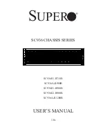
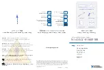
background image

SC748TQ-R1200B
SC748TQ-R1400B

SC748TQ-R1K43B


USER’S MANUAL 

1.0a

SC748 Chassis Series


S

UPER

®

Summary of Contents for SC748TQ-R1200B

Page 1: ...SC748TQ R1200B SC748TQ R1400B SC748TQ R1K43B USER S MANUAL 1 0a SC748 Chassis Series SUPER ...

Page 2: ... for the resolution of any such disputes Super Micro s total liability for all claims will not exceed the price paid for the hardware product FCC Statement This equipment has been tested and found to comply with the limits for a Class A digital device pursuant to Part 15 of the FCC Rules These limits are designed to provide reasonable protection against harmful interference when the equipment is o...

Page 3: ...and highly optimized design for dual core Xeon platforms The chassis is equipped with a redundant 1000 or 12000 Watt high efficiency power supply for superb power savings 3 hot swappable high performance fans provide ample optimized cooling for the chassis and 5 hot swap drive bays and 3 peripheral drive bays offer maximum storage capacity in a 4U form factor This document lists compatible parts a...

Page 4: ...ludes the functions and information provided by the control panel on the chassis as well as other LEDs located throughout the system Chapter 5 Chassis Setup and Maintenance Refer to this chapter for detailed information on this chassis You should follow the procedures given in this chapter when installing removing or reconfiguring your chassis Chapter 6 Rack Installation Refer to this chapter for ...

Page 5: ...v Preface Appendix A Chassis Cables Appendix B Power Supply Specifications Appendix C MT35TQ Mobile Rack Specifications Appendix D MT35S and MT35T Mobile Rack Specifications ...

Page 6: ...t Breaker 2 5 Power Disconnection Warning 2 6 Equipment Installation 2 8 Restricted Area 2 9 Battery Handling 2 10 Redundant Power Supplies 2 12 Backplane Voltage 2 13 Comply with Local and National Electrical Codes 2 14 Product Disposal 2 15 Hot Swap Fan Warning 2 16 Power Cable and AC Adapter 2 18 Chapter 3 Chassis Components 3 1 Components 3 1 Drives 3 1 Power Supply 3 1 Motherboards 3 1 Fans 3...

Page 7: ...5 2 5 4 Control Panel 5 3 Control Panel Orientation 5 3 5 5 Configuring Drives 5 5 Configuring the 5 25 Drive Bays 5 5 Additional Hard Drives 5 8 Installing Drives in the Storage Module 5 9 5 6 Installing the Motherboard 5 11 I O Shield 5 11 Permanent and Optional Standoffs 5 12 Procedure for Motherboard Installation 5 13 Power Supply Connections 5 14 5 7 Expansion Card Setup 5 15 5 8 Installing t...

Page 8: ...ndix A SC748 Chassis Cables Appendix B SC748 Power Supply Specifications Appendix C CSE M35TQ Mobile Rack Specifications C 1 ESD Safety Guidelines C 1 C 2 General Safety Guidelines C 1 C 3 An Important Note to Users C 1 C 4 Front Connectors and Jumpers C 2 Front Connectors C 2 C 5 Front Connector and Pin Definitions C 3 C 6 Front Jumper Locations and Pin Definitions C 5 Explanation of Jumpers C 5 ...

Page 9: ... bays offer maximum storage capacity in a 4U form factor 1 2 Shipping List Part Numbers Please visit the following link for the latest shipping lists and part numbers for your particular chassis model http www supermicro com products chassis 4U chs 748 Chapter 1 Introduction 1 1 SC748 Chassis Model HDD I O Slots Power Supply SC748TQ R1K43B 5x SAS SATA 7x FF 1400W Redundant Platinum level SC748TQ R...

Page 10: ...uper Micro Computer B V Het Sterrenbeeld 28 5215 ML s Hertogenbosch The Netherlands Tel 31 0 73 6400390 Fax 31 0 73 6416525 Email sales supermicro nl General Information support supermicro nl Technical Support rma supermicro nl Customer Support Web Site www supermicro com Asia Pacific Address Super Micro Computer Inc 3F No 150 Jian 1st Rd Zhonghe Dist New Taipei City 235 Taiwan R O C Tel 886 2 822...

Page 11: ... must be mailed when service is complete For faster service RMA authorizations may be requested online http www supermicro com support rma Whenever possible repack the chassis in the original Supermicro carton using the original packaging material If these are no longer available be sure to pack the chassis securely using packaging material to surround the chassis so that it does not shift within ...

Page 12: ...SC748 Chassis Manual 1 4 Notes ...

Page 13: ... configuring components in the Supermicro chassis These warnings may also be found on our web site at http www supermicro com about policies safety_information cfm Warning This warning symbol means danger You are in a situation that could cause bodily injury Before you work on any equipment be aware of the hazards involved with electrical circuitry and be familiar with standard practices for preve...

Page 14: ...o que le ayudará a encontrar el texto traducido en el apartado de traducciones que acompaña a este dispositivo GUARDE ESTAS INSTRUCCIONES IMPORTANTES INFORMATIONS DE SÉCURITÉ Ce symbole d avertissement indique un danger Vous vous trouvez dans une situation pouvant entraîner des blessures ou des dommages corporels Avant de travailler sur un équipement soyez conscient des dangers liés aux circuits é...

Page 15: ...ordat u aan enige apparatuur gaat werken dient u zich bewust te zijn van de bij een elektrische installatie betrokken risico s en dient u op de hoogte te zijn van de standaard procedures om ongelukken te voorkomen Gebruik de nummers aan het eind van elke waarschuwing om deze te herleiden naar de desbetreffende locatie BEWAAR DEZE INSTRUCTIES ً ف اًك أى ٌوكي حالة ً ف تتسبب اصابة جسذٌة الزهز هذا ًٌ ...

Page 16: ...ción antes de conectar el sistema a la red de alimentación Attention Avant de brancher le système sur la source d alimentation consulter les directives d installation 設置手順書 システムを電源に接続する前に 設置手順書をお読み下さい ال إرشادات اقر تركيب توصيل قبل إلى النظام للطاقة مصدر לקרוא יש למקור המערכת חיבור לפני התקנה הוראות את מתח 시스템을 전원에 연결하기 전에 설치 안내를 읽어주십시오 Waarschuwing Raadpleeg de installatie instructies voordat u h...

Page 17: ...liza el sistema de protección contra cortocircuitos o sobrecorrientes del edificio Asegúrese de que el dispositivo de protección no sea superior a 250 V 20 A Attention Pour ce qui est de la protection contre les courts circuits surtension ce produit dépend de l installation électrique du local Vérifiez que le courant nominal du dispositif de protection n est pas supérieur à 250 V 20 A על מסתמך זה ...

Page 18: ... es auf den Chassisinnenraum zurückgreift um Systemsbestandteile anzubringen oder zu entfernen Warning The system must be disconnected from all sources of power and the power cord removed from the power supply module s before accessing the chassis interior to install or remove system components 경고 이 제품은 전원의 단락 과전류 방지에 대해서 전적으로 건물의 관련 설비에 의존합니다 보호장치의 정격이 반드시 250V 볼트 20A 암페어 를 초과하지 않도록 해야 합니다 Waarsc...

Page 19: ... ou enlever des composants de systéme חשמלי ניתוק מפני אזהרה אזהרה החשמל מקורות מכל המערכת את לנתק יש להסיר ויש מהספק החשמלי כבל את התקנ לצורך המארז של הפנימי לחלק גישה לפני ת הסר או ת רכיבים فصم يجب اننظاو جميع من مصادر انطاقت وإزانت انكهرباء سهك من وحدة امداد انطاقت قبم إنى انىصىل انداخهيت انمناطق ن ههيكم إزانت أو نتثبيج مكىناث الجهاز 경고 시스템에 부품들을 장착하거나 제거하기 위해서는 섀시 내부에 접근하기 전에 반드시 전원 공급장치로부터 연결...

Page 20: ...et werden Advertencia Solamente el personal calificado debe instalar reemplazar o utilizar este equipo Attention Il est vivement recommandé de confier l installation le remplacement et la maintenance de ces équipements à des personnels qualifiés et expérimentés אזהרה רש בלבד מוסמך צוות את להחליף להתקין אי הציוד עבור שירות לתת או הציוד والمدربيه و لتزكيب استبدال أو خدمة الجهاس هذا يسمح أن يجب فقط ا...

Page 21: ... in Bereichen mit beschränktem Zutritt vorgesehen Der Zutritt zu derartigen Bereichen ist nur mit einem Spezialwerkzeug Schloss und Schlüssel oder einer sonstigen Sicherheitsvorkehrung möglich Advertencia Esta unidad ha sido diseñada para instalación en áreas de acceso restringido Sólo puede obtenerse acceso a una de estas áreas mediante la utilización de una herramienta especial cerradura con lla...

Page 22: ...ىص َمكن ً إن ىل منطقت محظورة فقط استخذاو خالل من خاصت أداة أو ٌ أ نال أخري وسُهت مألما ومفتاح قفم 경고 이 장치는 접근이 제한된 구역에 설치하도록 되어있습니다 특수도구 잠금 장치 및 키 또는 기타 보안 수단을 통해서만 접근 제한 구역에 들어갈 수 있습니다 Waarschuwing Dit apparaat is bedoeld voor installatie in gebieden met een beperkte toegang Toegang tot dergelijke gebieden kunnen alleen verkregen worden door gebruik te maken van speciaal gereedschap slot en sleut...

Page 23: ...ipo o el equivalente recomendado por el fabricante Desechar las baterías gastadas según las instrucciones del fabricante אזהרה סכנת קיימת פיצוץ תקינה לא בדרך והוחלפה במידה הסוללה של להחליף יש בסוג הסוללה את מ התואם חברת מומל יצרן צת הסוללות סילוק המשומשות לבצע יש היצרן הוראות לפי خطر هناك من اسحبذال حالة في انفجار البطارية صحيحة غير بطريقة فعليل البطارية اسحبذال فقط النىع بنفس يعادلها ما أو مما أو...

Page 24: ...té peut avoir plus d une connexion d alimentation Pour supprimer toute tension et tout courant électrique de l unité toutes les connexions d alimentation doivent être débranchées Redundant Power Supplies Warning This unit might have more than one power supply connection All connections must be removed to de energize the unit 冗長電源装置 このユニッ トは複数の電源装置が接続されている場合があります ユニッ トの電源を切るためには すべての接続を取り外さなければなりませ...

Page 25: ...idado cuando lo revise Attention Lorsque le système est en fonctionnement des tensions électriques circulent sur le fond de panier Prendre des précautions lors de la maintenance Warning Hazardous voltage or energy is present on the backplane when the system is operating Use caution when servicing قد لهذا يكون ال جهاز اتصاالت عدة بوحدات الطاقة امداد إزالة يجب االتصاالت كافة لعسل ال وحدة عن الكهرباء...

Page 26: ...be cumplir con las normas de electricidad locales y nacionales هناك خطز مه الكهزبائي التيار على المىجىدة أوالطاقة اللىحة يكىن عندما النظام يعمل عند حذرا كه خدمة الجهاس هذا 경고 시스템이 동작 중일 때 후면판 Backplane 에는 위험한 전압이나 에너지가 발생 합니다 서비스 작업 시 주의하십시오 Waarschuwing Een gevaarlijke spanning of energie is aanwezig op de backplane wanneer het systeem in gebruik is Voorzichtigheid is geboden tijdens het onderhou...

Page 27: ...اويه والىطىية المحلية المتعلقة بالكهرباء Attention L équipement doit être installé conformément aux normes électriques nationales et locales 경고 현 지역 및 국가의 전기 규정에 따라 장비를 설치해야 합니다 Waarschuwing Bij installatie van de apparatuur moet worden voldaan aan de lokale en nationale elektriciteitsvoorschriften 製品の廃棄 この製品を廃棄処分する場合 国の関係する全ての法律 条例に従い処理する必要が あります 警告 本产品的废弃处理应根据所有国家的法律和规章进行 警告 本產品的廢棄處理應根據所有國家的法律和規...

Page 28: ...ent Renseignez vous auprès de l organisme compétent Warning The fans might still be turning when you remove the fan assembly from the chassis Keep fingers screwdrivers and other objects away from the openings in the fan assembly s housing Hot Swap Fan Warning המוצר סילוק אזהרה ו להנחיות בהתאם להיות חייב זה מוצר של סופי סילוק המדינה חוקי النهائي التخلص من المنتج هذا معه التعامل ينبغي ل وفقا جميع ال...

Page 29: ...rde à ce que doigts tournevis et autres objets soient éloignés du logement du bloc ventilateur אזהרה חלקי את מסירים כאשר יש עובדים עדיין והמאווררים יתכן מהמארז המאוורר להרחיק ל המאוורר בתוך מהפתחים שונים עבודה וכלי האצבעות את בטוח מרחק انممكه مه انمراوح أن تسال ال إزانة تدورعند كتهة انمروحة انهيكم مه يجب إبقاء األصابع و انبراغي مفكات األشياء مه وغيرها بعيدا عه انفتحات في كتهة انمروحة 경고 섀시로부터 팬 조립...

Page 30: ...r Code für alle anderen elektrischen Geräte als Produkte von Supermicro nur bezeichnet gezeigt haben Advertencia Al instalar el producto utilice los cables de conexión previstos o designados los cables y adaptadores de CA La utilización de otros cables y adaptadores podría ocasionar un mal funcionamiento o un incendio Aparatos Eléctricos y la Ley de Seguridad del Material prohíbe el uso de UL o CS...

Page 31: ...צוין שלא تركيب عىذ استخذام يجب الجهاز و التىصيل كابالث الكهربائيت الكابالث ومحىالث المتردد التيار أن أي استخذام كابالث ومحىالث أخري يتسبب في عطل حذوث حريق أو التي لك تىفيرها تم المىتج مع UL أو CSA الكهربائيت األجهسة ومىاد قاوىن السالمت استخذام يحظر الكابالث قبل مه معتمذة Supermicro أجهسة أخري كهربائيت غير المىتجاث المعيىت قبل مه ألي UL CSA تحمل التي عالمت 경고 제품을 설치할 때에는 제공되거나 지정된 연결케이블과 전원케이블 AC어댑...

Page 32: ...2 20 SC748 Chassis Manual Notes ...

Page 33: ...ives or additional hard disk drives Power Supply The chassis includes two redundant 1400W or 1200W high efficiency power sup plies each with a low noise thermal control fan rated at 200 Watts The power supply modules are served by a power distributor Motherboards It supports Intel and AMD quad processors on motherboards of size up to 16 48 x 14 3 E ATX Quad processor motherboards 16 4 x 16 79 for ...

Page 34: ...le rack For detailed spe cific to your mobile rack information see the appendix at the back of this manual Mounting Rails The SC748 can be mounted in a rack 3 3 Where to get Replacement Components Though not frequently you may need replacement parts for your system To ensure the highest level of professional service and technical support we strongly recom mend purchasing exclusively from our Super...

Page 35: ...e user interface elements on the chassis are A control panel on the front that includes power buttons and status monitoring lights Status lights on externally accessable hard drives Status lights for the power supply visible from the back of the chassis Figure 4 1 Front LEDs ...

Page 36: ...keeps standby power supplied to the system Therefore you must unplug system before servicing Reset The reset button is used to reboot the system 4 2 Control Panel Buttons The chassis includes two push buttons that control power to the system Power Indicates power is being supplied to the system power supply units This LED should normally be illuminated when the system is operating HDD Indicates ha...

Page 37: ...D has been activated Use this function to locate the server in a rack mount environment Blinking blue Remote UID is on Use this function to identify the server from a remote location Ove There a Ove Some b changin at www Res If the s 1 Use 2 Con 3 Che ing 4 Veri Power Fail Indicates a power failure to the system s power supply units Overheating There are several possible responses if the system ov...

Page 38: ... blinks on and off when that particular drive is being accessed This function is controlled by the backplane Red When illuminated this LED indicates a drive failure You should be noti fied by your system management software 4 5 Power Supply LEDs On the rear of the power supply module an LED displays the status Solid Green When illuminated indicates that the power supply is on Solid Amber When illu...

Page 39: ...nformation in Chapter 2 and the warning precautions listed in the setup instructions 5 2 Removing Power from the System Before performing most setup or maintenance tasks use the following procedure to ensure that power has been removed from the system 1 Use the operating system to power down the system following the on screen prompts 2 After the system has completely shut down carefully grasp the ...

Page 40: ...oving the Chassis Cover Removing the Chassis Cover 1 Remove the two screws securing the cover to the chassis 2 Press the release tabs simultaneously 3 Slide the cover forward Figure 5 1 Removing the Chassis Cover Remove Screws 4 3 2 3 ...

Page 41: ...r either tower or server rack orientation It is shipped in tower mode and can be immediately used as desktop server To use it in a rack rotate the module that contains the control panel and the three drive trays 1 in Figure 5 2 90 degrees Figure 5 2 Chassis in Tower Mode Default Configuration Storage Module Drive Trays Control Panel 1 Control Panel Drive Module Figure 5 3 Chassis in Rack Mount Mod...

Page 42: ...dule to any component in the chassis 3 Push the module release lever to unlock the module Figure 5 4 4 Grasp the external edges of the module and pull the unit from the chassis 5 Rotate the module 90 degrees so that the control panel is on top 6 Reinsert the module into the chassis and reconnect the cables Caution Use caution when working around the backplane Do not touch the backplane with any me...

Page 43: ...ront control panel It can be set up in a variety of configurations to suit the user s needs Three peripheral drives such as CD DVD or floppy Additional fixed hard drives in an individual bay A combination of the above A mobile rack with five additional 3 5 hot swappable hard drives Installing a Hard Drive into a Drive Tray 1 Open the chassis cover 2 Locate the drive tray and pull the tray release ...

Page 44: ... from the bottom 6 Slide the drive tray into the chassis until the tray clicks into place Note Enterprise level hard disk drives are recommended for use in Supermicro chassis and servers For information on recommended HDDs visit the Supermicro Web site at http www supermicro com products nfo files storage SAS CompList pdf Caution When the server is operating all the drive trays should remain in th...

Page 45: ...t any standard sized peripheral 6 Slide the drive into the chassis until it clicks into place Drive Rails Drive Tray Figure 5 7 Removing Rails from the Drive Tray Adding Peripheral Drives to the Drive Bays Replace a drive tray with a peripheral drive 1 Open the chassis cover 2 Locate the release tab for the drive tray where you want to place the peripheral drive Figure 5 5 3 Push the drive tray to...

Page 46: ...le Rack 1 Open the chassis cover 2 Press the drive tray release tabs Figure 5 5 3 Push all three drive trays forward and out of the chassis 4 Remove the six drive tray rails Figure 5 7 Figure 5 8 Add Rails to the Mobile Rack Two shown as an example install six Mobile Rack Rails 5 Install all six rails onto the mobile rack Each rail requires two screws Make sure the arrow on the rail points toward ...

Page 47: ...val These carriers also help promote proper airflow for the drive bays Installing Hard Drives 1 Press the release button to extend the drive tray handle 2 Using the handle pull the drive tray out by the handle The drive is hot swappable there are no cables to disconnect Figure 5 9 Remove the screws holding the drive tray to the dummy drive Figure 5 9 Install Hard Drives Drive Tray Handle Release B...

Page 48: ...ing four screws Figure 5 11 5 Insert the hard drive into the chassis To do this a Press the hard drive release button to extend the drive tray handle b Insert the drive tray assembly into the chassis and close the handle to lock the drive tray into place Drive Tray SAS SATA Drive 3 Place a hard drive in the drive tray Figure 5 10 ...

Page 49: ...hield Installing the I O Shield 1 Review the documentation that came with your motherboard Become familiar with component placement requirements and precautions 2 Open the chassis cover 3 Choose the proper I O shield for the motherboard you are installing 4 With the illustrations facing the outside of the chassis place the shield into the space provided Once installed the motherboard ports will ho...

Page 50: ...s by securing space between the motherboard and the chassis surface The SC748 chassis packaging includes optional standoffs hexagon shaped posts These standoffs accept the rounded Phillips head screws included in the SC748 accessories packaging Figure 5 13 Chassis Standoffs Chassis Standoffs ...

Page 51: ...4 As required by your motherboard install standoffs in any areas that do not have a permanent standoff To do this a Place a hexagonal standoff screw through the bottom the chassis b Secure the screw with the hexagon nut rounded side up 5 Lay the motherboard on the chassis aligning the permanent and optional standoffs 6 Secure the motherboard to the chassis using the rounded Phillips head screws 7 ...

Page 52: ...ble 2 Backplane Each cable has 3 connectors two hard drive and one floppy drive Attach the hard drive connectors to the backplane If you are using a Supermicro back plane the floppy drive connector does not need to be attached 8 pin mother board cable 1 Mother board Provides power to the motherboard CPU This cable has 2 black and 2 yellow wires 4 pin mother board cable 1 Mother board Provides powe...

Page 53: ...ds to the chassis such as PCI cards Installing Expansion Cards 1 Locate the release tab on the top of the PCI bracket 2 Gently apply pressure in the middle of the release tab to unlock the PCI Slot bracket 3 Pull the release tab upward Press the Middle of the Release Tab Lift the Release Tab Figure 5 15 Expansion Card Port ...

Page 54: ...this slide the expansion card with L bracket into the PCI slot and secure the card to the motherboard 6 Push the PCI bracket release tab down until it locks into place with an audible click 7 Secure the expansion card with the screw previously removed from the chassis 8 Repeat this process with each expansion card you want to install into the chassis Figure 5 16 Remove PCI Card Slot Guard ...

Page 55: ... that can be removed if motherboard components prevent the air shroud from fitting securely Remove tabs only if necessary Intel CPU Users The air shroud for use with Intel CPUs does not require any additional modification Installing the Air Shroud 1 Remove the chassis cover 2 Place air shroud in your chassis with the fan side touching the edge of the two fans closest to the power supply The other ...

Page 56: ...ly Do not operate the server without drives or drive trays in the drive bays Use only recommended server parts Make sure no wires or foreign objects obstruct air flow through the chassis Pull all excess cabling out of the airflow path or use shorter cables Installation Complete In most cases the chassis power supply and fans are pre installed If you need to install them continue through this chapt...

Page 57: ...nt Fan Replacement Procedure 1 Open the chassis cover and determine which fan has failed Because the fans are hot swappable the chassis does not have to be powered down 2 Press the fan release tab and lift the failed fan from the chassis Front fans must be pulled straight up 3 Place the new fan into the vacant space in the housing while making sure the arrows on the top of the fan indicating air d...

Page 58: ...ear Chassis Fan Rear Fan Replacement Procedure 1 Press the rear fan release tab 2 Remove the fan from the chassis by pulling the top of the fan toward the rear of the chassis 3 Place the new fan in the chassis bottom first 4 Push the fan fully into the housing until the fan clicks into place ...

Page 59: ...edundant power supply models the system automatically switches to the second power supply when the first fails Replacing the Power Supply 1 The power cords attach in the rear of the chassis Remove the cord that cor responds to the module to be replaced 2 On the front of the chassis push the release button on the power supply mod ule Figure 5 21 3 Pull the power supply out using the handle provided...

Page 60: ...SC748 Chassis Manual 5 22 Figure 5 21 Removing a Power Supply Press the Release Button 2 3 Pull the Drive Out Using the Handle ...

Page 61: ...ring for Setup Decide on a suitable location for the rack unit that will hold your chassis It should be situated in a clean dust free area that is well ventilated Avoid areas where heat electrical noise and electromagnetic fields are generated Place it near a grounded power outlet Choosing a Setup Location Leave enough clearance in front of the rack to enable you to open the front door completely ...

Page 62: ...ift in place as a precaution in case the test fails In any instance of pulling the system from the rack always use a rack lift and follow all associated safety precautions General Server Precautions Review the electrical and general safety precautions that came with the com ponents you are adding to your chassis Determine the placement of each component in the rack before you install the rails Ins...

Page 63: ...rloading of circuits might have on overcurrent protection and power supply wiring Appropriate consideration of equipment nameplate ratings should be used when addressing this concern Reliable Ground A reliable ground must be maintained at all times To ensure this the rack itself should be grounded Particular attention should be given to power supply connec tions other than the direct connections t...

Page 64: ... bottom feet must be removed to mount in a rack Also the control panel drive module should be rotated 90 degrees See Chapter 4 for this procedure Removing the Tower Cover and Feet The SC748 chassis is shipped with the chassis cover and feet installed Both must be removed for before installing the rails Removing the Tower Top Cover 1 Locate the chassis cover lock blue lever at the rear of the chass...

Page 65: ...ssis on its side with the chassis side cover facing upward 2 Remove the screw holding a chassis foot in place 3 The foot lock is a tab located in the center of the foot that prevents the foot from sliding Using a flat head screwdriver gently lift the foot lock upward and slide the foot toward the rear of the chassis 4 Repeat steps 2 and 3 with each remaining foot ...

Page 66: ... consists of two sections an inner fixed chassis rail that secures directly to the server chassis and an outer fixed rack rail that secures directly to the rack itself Installing the Chassis Handles and Inner Rails 1 Locate the chassis handles 2 and handle screws 6 2 Align the chassis handle with the front of the chassis and secure with the three chassis handle screws 3 Repeats steps 1 and 2 with ...

Page 67: ...s 4 Locate the inner rails 2 and screws 12 in the shipping package 5 Align the inner rails against the chassis as shown Confirm that the rails are flush against the edge of the chassis 6 Tighten the screws Do not over tighten 7 Repeat steps 5 and 6 with the other inner rail ...

Page 68: ...ide of the long bracket Both bracket ends must face the same direction 2 Adjust both the brackets to the proper distance so that the rail fits snugly into the rack Figure 6 5 Assembling the Outer Rails The right side rail is pictured Secure to the Front of the Rack Secure to the Rear of the Rack Attach to Rear Bracket ...

Page 69: ...uter rail with two M5 screws and the rear side of the outer rail with three M5 screws Note The outer rail is adjustable from approximately 26 to 38 25 4 Repeat steps 1 3 for the left outer rail Stability hazard The rack stabilizing mechanism must be in place or the rack must be bolted to the floor before you slide the unit out for servicing Failure to stabilize the rack can cause the rack to tip o...

Page 70: ...ing the Chassis into a Rack 1 Confirm that chassis includes the inner rails and the outer rails 2 Line chassis rails with the front of the rack rails C 3 Slide the chassis rails into the rack rails keeping the pressure even on both sides you may have to depress the locking tabs when inserting When the server has been pushed completely into the rack you should hear the locking tabs click ...

Page 71: ...to return the chassis to tower mounting Installing the Chassis Cover 1 Remove the rack mount handles 2 Align the cover post with the corresponding holes on the top of the chassis and place the cover on top of the chassis The cover should overhang approximately one half inch over the front of the chassis 3 Slide the chassis cover toward the rear of the chassis to lock the cover into place Add the C...

Page 72: ...nd slide the foot toward the front of the chassis The foot should lock into place 2 Secure the foot to the chassis using one screw enclosed in the packaging 3 Repeat steps 1 and 2 for the remaining three chassis feet Figure 6 9 Replacing Chassis Feet Chassis Foot Receptacle Chassis Foot Chassis Screw ...

Page 73: ... the manufacturer of the motherboard you are using and our Web site at www supermicro com A 2 Cables Included with SC748TQ Chassis SAS SATA SC748TQ R1200 and SC748TQ R1000 Part Type Length Description CBL 0044L Cable 24 Serial ATA lead free CBL 0051L Cable 60cm Round floppy cable CBL 0084 Cable 6 Split converter cable CBL 0087 Ribbon Round 20 16 pin to 16 pin ribbon cable for control panel CBL 020...

Page 74: ...ble has one SFF 8484 32 pin connector on one end and 4 SAS connectors 7 pins each at the other This cable connects from the Host motherboard or other controller to the backplane SAS hard drive port Cable Name SAS Cable Quantity 1 Part CBL 0175L Alt Name Big Four Description This cable has one ipass SFF 8087 mini sas connector 36 pins at one end and 4 SAS connectors on one end This cable connects f...

Page 75: ...20 pin CBL 0059 7 9 20 CM 8 pin CBL 0062 7 9 20 CM 4 pin CBL 0060 7 9 20 CM Front Panel to the Motherboard The SC748 chassis includes a cable to connect the chassis front panel to the motherboard If your motherboard uses a different connector use the following list to find a compatible cable Front Panel to Motherboard Cable Ribbon Cable Number of Pins Front Panel Number of Pins Motherboard Cable P...

Page 76: ...SC748 Chassis Manual A 4 Notes ...

Page 77: ...rt PWS 1K41F 1R Rated AC Voltage 1200W 100 140V 50 60Hz 10 5 14 7 Amp 1400W 180 240V 50 60Hz 7 2 9 5 Amp 5V standby 6 Amp 12V 100 Amp 100 140V 117 Amp 180 240V With Power Distributer 5V 30 Amps 12V 0 6 Amp 3 3V 25 Amp SC748TQ R1200B 1200W Redundant high efficiency power supply with PMBus MFR Part PWS 1K22 1R Rated AC Voltage 100 240V 50 60Hz 6 15 Amp 5V standby 4 Amp 12V 100 Amp With Power Distrib...

Page 78: ...t High efficiency AC power supply with Digital Switching Control PMBus 1 2 MFR Part PWS 1K43F 1R Rated AC Voltage 100 240 V 50 60 Hz 15 Amp max 5V standby 6 Amp 12V 100 Amp 100 140V 117 Amp 180 240V With Power Distributer 5V 30 Amps 12V 0 6 Amp 3 3V 25 Amp ...

Page 79: ...rd by its edges only do not touch its components peripheral chips memory modules or gold contacts When handling chips or modules avoid touching their pins Put the card and peripherals back into their antistatic bags when not in use C 2 General Safety Guidelines Always disconnect power cables before installing or removing any components from the computer including the mobile rack Disconnect the pow...

Page 80: ...JP10 and JP13 2 Chip MG 9072 3 JTAG JP47 4 I2 C Connector 1 JP44 5 I2 C Connector 2 JP45 6 SideBand Connector 1 JP51 7 SideBand Connector 2 JP52 8 Upgrade JP46 9 ACT IN JP26 10 FAN Connector JP22 11 SAS Port 0 J5 12 SAS Port 1 J6 13 SAS Port 2 J7 14 SAS Port 3 J8 15 SAS Port 4 J10 11 4 10 9 8 1 5 7 6 3 2 12 13 14 15 ...

Page 81: ...in connectors designated JP10 and JP13 provide power to the mobile rack See the table on the right for pin definitions 3 JTAG Connector The JTAG connector designated JP47 is used for diagnostic purposes only This connector should only be used a certified and experi enced technician 4 and 5 I2 C Connectors The I2 C Connectors designated JP44 and JP45 are used to monitor HDD activity and status See ...

Page 82: ...obile rack ID SB7 7 SCL SB0 10 No Connec tion 9 No Connec tion SAS Activity LED Header Pin Definitions JP26 Pin Definition Pin Definition 1 ACT IN 0 6 ACT IN 4 2 ACT IN 1 7 ACT IN 5 3 ACT IN 2 8 ACT IN 6 4 ACT IN 3 9 ACT IN 7 5 Ground 10 Empty 10 Fan Connector The 3 pin connectors designated JP22 pro vide power to the mobile rack fan See the table on the right for pin definitions Fan Connectors JP...

Page 83: ...ngs Jumpers create shorts between two pins to change the function of the connector Pin 1 is identified with a square solder pad on the printed circuit board Note On two pin jumpers Closed means the jumper is on and Open means the jumper is off the pins Connector Pins Jumper Setting 3 2 1 3 2 1 REV 1 01 SASM35TQ R S UPER REV 1 01 SASM35TQ R S UPER JP37 JP34 JP36 JP33 JP42 JP43 JP62 JP38 JP18 JP50 J...

Page 84: ...t configure both jumpers as instructed below Fan Jumper Settings Jumper Jumper Settings Note JP61 Closed With Fan Open No Fan FAN 1 JP62 Pins 1 2 With Fan Pins 2 3 No Fan FAN 1 Jumper Settings Jumper Jumper Settings Notes JP18 Open Enabled Closed Disabled Buzzer Reset JP29 Open Default Closed Reset 9072 Chip Reset ...

Page 85: ...P33 2 3 Controller ID 1 JP34 1 2 ID 0 Backplane ID 1 JP36 2 3 Controller ID 2 JP37 2 3 ID 1 Backplane ID 2 JP38 Closed I2 C Reset 2 JP40 Open I2 C Reset SDOUT 1 JP41 Open I2 C Reset SDOUT 2 JP42 2 3 Backplane ID SDIN 1 JP43 2 3 Backplane ID SDIN 2 JP50 Closed I2 C Reset 1 SGPIO Setting Jumper Jumper Setting Note JP33 1 2 Controller ID 1 JP34 1 2 ID 0 Backplane ID 1 JP36 1 2 Controller ID 2 JP37 1 ...

Page 86: ... Use the following chart when connecting this mobile rack If you connect the SAS ports out of order you will not able to easily identify drives using the LED func tion SAS Port Connections in I2C and SGPIO Settings Port I2 C SGPIO 0 3 I2 C 1 Sideband 1 4 I2 C 2 Sideband 2 ...

Page 87: ...ector SAS Drive Number SAS 0 SAS SATA HHD 0 SAS 1 SAS SATA HHD 1 SAS 2 SAS SATA HHD 2 SAS 3 SAS SATA HHD 3 SAS 4 SAS SATA HHD 4 1 SAS 0 SAS 2 SAS 3 SAS 4 SAS SAS 0 J1 FAIL 0 FAIL 1 FAIL 2 FAIL 3 FAIL 4 ACT 0 ACT 1 ACT 2 ACT 3 ACT 4 SAS 1 J2 SAS 2 J3 SAS 3 J4 SAS 4 J9 1 SAS 0 SAS 2 SAS 3 SAS 4 SAS FAN FAIL OH DRIVE FAIL D4 D3 ...

Page 88: ...ure LED SAS 0 D12 D5 SAS 1 D13 D6 SAS 2 D14 D7 SAS 3 D15 D8 SAS 4 D18 D19 Mobile Rack Backplane LEDs LED Hard Drive Activity Failure LED D3 ON Overheat Drive Failure LED indicator Red light flashing buzzer on D4 ON Overheat Drive Failure LED indicator Red light flashing buzzer on ...

Page 89: ...follow the guidelines listed below Before accessing the Mobile Rack 1 Turn off all peripheral devices and the power supply connected to the chassis and unplug all power cords from the system or the wall outlets 2 Disconnect all the cables and label the cables for easy identification 3 Use a grounded wrist strap designed to prevent static discharge when han dling components 4 Save all the screws an...

Page 90: ...obile rack you must remove the exhaust fan In some circumstances the backplane may need to be removed Figure C 1 Pinch the Tabs on the Mobile Rack Fan Connecting SAS SATA and Power Cables to the Mobile Rack 1 Begin removing the exhaust fan by pinching the tabs on each side of the unit as illustrated ...

Page 91: ...C 13 Appendix C CSE M35TQ Mobile Rack Specifications Figure C 2 Pull Fan from the Rack 2 Pull the exhaust fan from the chassis ...

Page 92: ... C 3 Removing Bracket from Rack 3 Remove the bracket screw and pull the bracket from the mobile rack 4 Connect the SAS cables and power cables to the mobile rack backplane 5 Replace the bracket bracket screw and fan to the mobile rack ...

Page 93: ...E M35TQ Mobile Rack Specifications Figure C 4 Removing the Backplane from the Mobile Rack Backplane Removal The backplane may be separated from the mobile rack by removing the seven screws holding the backplane in place ...

Page 94: ... be reasonably expected to result in significant injury or loss of life or catastrophic property damage Accordingly Supermicro disclaims any and all liability and should buyer use or sell such products for use in such ultra hazardous applications it does so entirely at its own risk Furthermore buyer agrees to fully indemnify defend and hold Supermicro harmless for and against any and all claims de...

Reviews: