background image

SC836 CHASSIS

Series

SC836TQ - R800V(B)

SC836E1 - R800V(B)

SC836E2 - R800V(B)


USER’S MANUAL

1.0d

S

UPER

Summary of Contents for SC836E1 - R800V(B)

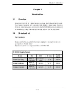
Page 1: ...SC836 CHASSIS Series SC836TQ R800V B SC836E1 R800V B SC836E2 R800V B USER S MANUAL 1 0d SUPER ...

Page 2: ...Y TO USE THIS PRODUCT OR DOCUMENTATION EVEN IF ADVISED OF THE POSSIBILITY OF SUCH DAMAGES IN PARTICULAR THE VENDOR SHALL NOT HAVE LIABILITY FOR ANY HARDWARE SOFTWARE OR DATA STORED OR USED WITH THE PRODUCT INCLUDING THE COSTS OF REPAIRING REPLACING INTEGRATING INSTALLING OR RECOVERING SUCH HARDWARE SOFTWARE OR DATA Any disputes arising between manufacturer and customer shall be governed by the law...

Page 3: ...SC836 3U chassis features a unique and highly optimized design for dual core Xeon platforms The chassis is equipped with a redundant 800W high efficiency power supply High performance fans provide ample optimized cooling for FB DIMM memory modules and 16 hot swap drive bays offers maximum storage capacity in a 3U form factor This document lists compatible parts available when this document was pub...

Page 4: ...SC836 Chassis Manual iv Notes ...

Page 5: ...nents Chapter 4 System Interface Refer to this chapter for details on the system interface which includes the functions and information provided by the control panel on the chassis as well as other LEDs located throughout the system Chapter 5 Chassis Setup and Maintenance Refer to this chapter for detailed information on this chassis You should follow the procedures given in this chapter when inst...

Page 6: ... backplanes Not all compatible backplanes are listed Refer to our Web site for the latest compatible backplane information Appendix A SC836 Chassis Cables Appendix B SC836 Power Supply Specifications Appendix C SAS 836EL Series Backplane Manual Appendix D SAS 836TQ Backplane Manual Appendix E Power Control Card CSE PTJBOD CB1 ...

Page 7: ...ical Safety Precautions 2 1 2 5 General Safety Precautions 2 2 2 6 System Safety 2 3 Chapter 3 Chassis Components 3 1 Overview 3 1 3 2 External Components 3 1 3 3 Internal Components 3 3 Chapter 4 System Interface 4 1 Overview 4 1 4 2 Control Panel 4 2 4 3 Control Panel LEDs 4 2 4 4 Drive Carrier LEDs 4 4 Chapter 5 Chassis Setup 5 1 Overview 5 1 5 2 Installation Steps 5 1 5 3 installation Step 1 R...

Page 8: ...ear system fans 5 11 To check the server s air flow 5 12 5 7 Chassis Maintenance 5 13 System Fans 5 13 Replacing a system fan 5 13 Power Supply 5 14 Replacing the Power Supply 5 14 Replacing the Power Distributor 5 15 Replacing the DVD Rom Floppy Drive and Front Panel 5 16 To replace or install the DVD drive 5 17 To replace or install the Floppy drive 5 17 To replace or install the Front Panel 5 1...

Page 9: ...ting Considerations 7 2 7 4 Rack Mounting Instructions 7 4 To install the rack rails 7 5 Outer Rack Rails 7 6 To install the outer rack rails 7 6 Installing the chassis into a rack 7 7 Appendices Appendix A SC836 Chassis Cables A 1 Appendix B SC836 Power Supply Specifications B 1 Appendix C SAS 836EL Series Backplane C 1 Appendix D SAS 836TQ Backplane D 1 Appendix E Power Control Card CSE PTJBOD C...

Page 10: ...SC836 Chassis Manual x Notes ...

Page 11: ... 16 hot swap drive bays offer maximum storage capacity in a 3U form factor 1 2 Shipping List Part Numbers Please visit the following link for the latest shipping lists and part numbers for your particular chassis model http www supermicro com products chassis 3U chs 836 SC836 Chassis Series Model CPU HDD I O Slots Power Supply SC836TQ R800V B DP Dual core Xeon 16x SAS SATA 7x FF R800W SC836E1 R800...

Page 12: ...hot swappable In other words once setup correctly these drives can be removed without powering down the server In addition these drives support SAF TE SCSI and SES2 SAS SATA I O Expansion slots Each version of the SC836 Chassis includes 7 full I O expansion slots Peripheral Drives Each SC836 Chassis supports one slim DVD ROM Drive included and one slim Floppy Drive optional These drives allow you ...

Page 13: ...ss SuperMicro Computer B V Het Sterrenbeeld 28 5215 ML s Hertogenbosch The Netherlands Tel 31 0 73 6400390 Fax 31 0 73 6416525 Email sales supermicro nl General Information support supermicro nl Technical Support rma supermicro nl Customer Support Asia Pacific Address SuperMicro Taiwan 4F No 232 1 Liancheng Rd Chung Ho 235 Taipei County Taiwan R O C Tel 886 2 8226 3990 Fax 886 2 8226 3991 Web Site...

Page 14: ...SC836 Chassis Manual 1 4 Notes ...

Page 15: ...assis It should be situated in a clean dust free area that is well ventilated Avoid areas where heat electrical noise and electromagnetic fields are generated You will also need it placed near at least two grounded power outlets The SC836 chassis includes two redundant power supplies which require two grounded out lets 2 3 Preparing for Setup The SC836 Chassis includes a set of rail assemblies inc...

Page 16: ...hock Use extreme caution when using metal tools which can easily damage any electrical components or circuit boards they come into contact with l Do not use mats designed to decrease electrostatic discharge as protection from electrical shock Instead use rubber mats that have been specifically designed as electrical insulators l The power supply power cord must include a grounding plug and must be...

Page 17: ...ted by two objects with different electrical charges coming into contact with each other An electrical discharge is created to neutralize this difference which can damage electronic components and printed circuit boards The following measures are generally sufficient to neutralize this difference before contact is made to protect your equipment from ESD l Do not use mats designed to decrease elect...

Page 18: ...hing their pins l Put the serverboard and peripherals back into their antistatic bags when not in use l For grounding purposes make sure your computer chassis provides excel lent conductivity between the power supply the case the mounting fasten ers and the serverboard ...

Page 19: ...arately For the latest shipping lists visit our Web site at http www supermicro com Backplane Each SC836 chassis comes with a 3U backplane Depending on our order your backplane will accept SAS SATA drives SAS only or SCSI drives For more in formation regarding compatible backplanes view the appendices found at the end of this manual In addition visit our Web site for the latest information http ww...

Page 20: ...that funnel air directly to where it is needed Always use the air shroud included with your chassis 3 3 Where to get Replacement Components Though not frequently you may need replacement parts for your system To en sure the highest level of professional service and technical support we strongly recommend purchasing exclusively from our Supermicro Authorized Distributors System Integrators Reseller...

Page 21: ...keep you constantly informed of the overall status of the system as well as the activity and health of specific components Most SC836 models are two buttons on the chassis a control panel a reset button and an on off switch This chapter explains the meanings of all LED indicators and the appropriate response you may need to take Figure 4 1 SC836 Front Panel ...

Page 22: ...ystem Turning off system power with this but ton removes the main power but keeps standby power supplied to the system Therefore you must unplug system before servicing 4 3 Control Panel LEDs The control panel located on the front of the SC836 chassis has 6 LEDs These LEDs provide you with critical information related to different parts of the system This section explains what each LED indicates w...

Page 23: ...the system or the ambient room tem perature being too warm Check the routing of the cables and make sure all fans are present and operating normally You should also check to make sure that the chassis covers are installed Finally verify that the heatsinks are installed properly This LED will remain flashing or on as long as the overheat condition exists l NIC2 Indicates network activity on LAN2 wh...

Page 24: ...blue LED on the front of the drive carrier indicates drive activity A connection to the SAS backplane enables this LED to blink on and off when that particular drive is being accessed l Red The red LED to indicate a drive failure If one of the SAS drives fail you should be refer to your system management software ...

Page 25: ...ssis Cover Step 2 Install Hard Drives A Remove Hard Drive Trays from the Chassis B Install a Hard Drive to the Hard Drive Tray Step 3 Install the Motherboard includes Power Supply and I O Slot Setup Step 4 Install Air Shroud Rear Fans and Check Airflow A Install Air Shroud B Install Rear Fan C Check Airflow Review the warnings and precautions listed in the manual be fore setting up or servicing th...

Page 26: ...need to remove the chassis cover screw 2 Once the top cover is released from the locked position slide the cover toward the rear of the chassis and lift the cover off the unit Figure 5 1 Removing the Chassis Cover Release Tab Remove this screw if necessary Warning Except for short periods of time do NOT operate the server without the cover in place The chassis cover must be in place to allow prope...

Page 27: ...ing the tray use the handle to lock the tray into place 5 4 Installation Step 2 Install Hard Drives The drives are mounted in drive trays to simplify their installation and removal from the chassis To install a hard drive to the hard drive tray 1 Remove the screws 2 securing the dummy drive to the drive tray and separate the dummy drive Figure 5 2 Removing Dummy Drive from Tray Drive Tray Dummy Dr...

Page 28: ...g holes in the hard drive and the tray Make sure the bottom of the hard drive and bottom of the hard drive tray are flush 5 Secure the hard drive using all six 6 screws 6 Replace the drive tray into the chassis Make sure to close the drive tray using the drive tray handle Hard Drive Tray SAS SATA or SCSI Hard Drive Figure 5 3 Install SAS or SATA Drive to Hard Drive Tray Use a Hard Stable Surface w...

Page 29: ...ure a hexagonal post by screwing it into the necessary spot Standoffs Labeling Standoff locations are labeled on the bottom of the SC836 chassis with the letters P D and A P Most compatible motherboards have a processor or CPU located here If necessary place standoffs here for the CPU s heatsink D Place optional standoffs here if your motherboard requires additional posts to hold the unit in place...

Page 30: ...ired by your motherboard install standoffs in any areas that do not have a permanent standoff To do this tighten a hexagonal optional standoff into the chassis 6 Lay the motherboard on the chassis aligning the permanent and optional standoffs 7 Secure the motherboard to the chassis using the rounded Phillips head screws 8 Secure the CPU s and heatsinks to the motherboard ...

Page 31: ...ch cable has 3 connectors two Hard Drive HDD and one Floppy Drive FDD Attach the HDD connectors to the backplane If you are using a SuperMicro backplane the FDD con nector does not need to be attached 8 pin mother board cable 1 mother board Provides power to the motherboard CPU This cable has 2 black and 2 yellow wires 4 pin mother board cable 1 mother board Provides power to PCI expansion card Th...

Page 32: ...board slot If the Add On card requires a riser card install it at this time If necessary slide the card into the PCI card guide and lock Never force a component into a motherboard or the chassis 5 Secure the expansion add on card with the screw from the I O panel I O Shield and Add On Card Setup The SC836 chassis includes space for an I O shield and up to seven Add On Ex pansion cards Figure 5 4 S...

Page 33: ...herboard you must remove the existing port shield and replace with the new one or use the existing the shield to slide the ports through 4 Connect the port panel to the motherboard following the motherboard docu mentation PS 2 ports USB ports Parallel port Serial COM ports VGA or Video port LAN port Figure 5 5 SC836 Chassis Port Panel ...

Page 34: ...mize fan efficiency The SC836 chassis air shroud does not require screws to set up To install the air shroud 1 Remove the chassis cover If necessary remove the rear fans 2 Place the air shroud in the chassis as illustrated The shroud aligns with the fan holders and covers two of the front fans with two of the rear fans Make sure the air shroud aligns completely with the chassis ...

Page 35: ...ir shroud setup Rear System Fans Installing the rear system fans 1 Confirm that the air shroud is correctly placed 2 Slide the rear fan into the slot as illustrated The fan release tab should be on the side closest to the power supply 3 Make sure that the fan is secure in the fan housing and the housing is cor rectly connected to the power supply Figure 5 7 Install the Rear Fan ...

Page 36: ...the cable rack 2 Do not operate the server without drives or drive trays in the drive bays 3 Use only recommended server parts 4 Make sure no wires or foreign objects obstruct air flow through the chassis Pull all excess cabling out of the airflow path or use shorter cables 5 Do not operate the server for extended periods of time without the air shroud in the proper place ...

Page 37: ...s may be removed and replaced without having to power down the server 5 7 Chassis Maintenance Replacing a system fan 1 Open the chassis and locate the faulty fan Never run the server for an ex tended period of time with the chassis open 2 Press the release tab on the fan and pull the fan upward 3 Slide the new fan into the fan housing Make sure the power connectors are correctly aligned The new fa...

Page 38: ...t two power modules you can leave the server running if you remove only one power sup ply at a time 2 Unplug the power supply that you will replace 3 Push the release tab on the back of the power supply as illustrated 4 Pull the power supply out using the handle provided 5 Replace the failed power module with the same model 6 Push the new power supply module into the power bay until you hear a cli...

Page 39: ...supply to the motherboard backplane and other components Also remove both power supplies 3 Locate the power distributor between the power supply and the fan row 4 Remove the three screws securing the power supply 5 Gently pull the power distributor from the chassis Make the guide all the cables through the power distributor housing 6 Slide the new power distributor module into the power distributo...

Page 40: ...lim Floppy Drive and Front Port Panel Use the instructions in this section in the unlikely event that you must replace any of these components The DVD ROM goes into the right slot The Floppy Drive goes into the left slot The Front Panel goes into the center slot Figure 5 10 Install the DVD ROM Front Panel and Floppy Drive ...

Page 41: ...the backplane and if necessary motherboard For more information see the manual for your backplane in the appendix To replace or install the Floppy drive 1 Power down and unplug the system 2 Remove the chassis cover 3 If you are not installing a new front port panel Remove the mini bezel grate from the drive bay The mini bezel is the small grating that covers the drive bay Remove this by simply pul...

Page 42: ...grating that covers the drive bay Remove this by simply pulling it out of the bay If you are installing a new front port panel Remove the old front port panel by depressing the release tab then pulling the front port panel out of the chassis 4 Insert the new unit in the slot until the tab locks into place 5 Connect the data and power cables to the backplane and if necessary motherboard For more in...

Page 43: ... an 836EL series backplane or you do not want to take advantage of the advanced features you can skip this chapter Specific examples and cascading instructions can be found in the SC836 Backplane Manual located in the Appendix section Review the warnings and precautions listed in the manual be fore setting up or servicing this chassis These include infor mation in Chapter 2 System Safety and the w...

Page 44: ...Note Both 836EL series backplanes support SAS drives only PRI_J0 PRI_J1 PRI_J2 SEC_J0 SEC_J1 SEC_J2 J2 J1 J0 Port A Primary Ports To HBA or higher backplane From Lower Backplane in cascaded system SC 836E2 Single Port Backplane SC 836E2 Dual Port Backplane PRI_J0 PRI_J1 PRI_J2 SEC_J0 SEC_J1 SEC_J2 J2 J2 J1 J1 Port B Secondary Ports Expander 2 To HBA or higher backplane From Lower Backplane in casc...

Page 45: ...ective failover and recovery This feature is not supported by the SC 836EL1 backplane Single Host Bus Adapter In a single host bus configuration the backplane connects to one Host Bus Adapter HBA PRI_J0 PRI_J1 PRI_J2 SEC_J0 SEC_J1 SEC_J2 J17 WWN SAS HBA Port A Expander 1 Port B Expander 2 PRI_J0 PRI_J1 PRI_J2 SEC_J0 SEC_J1 SEC_J2 J17 WWN SAS HBA Port A Expander 1 Port B Expander 2 Single Host Bus ...

Page 46: ...Adapter Failover If the Expander or data path in Port A fails the system will automatically fail over to Port B This maintains a full connection to all drives 6 4 Cascading Backplanes The SC 836 chassis supports cascading when coupled with an 836EL series backplane or other Supermicro backplane with Expander capabilities Power Control Card In a cascaded configuration backplanes can be linked to cr...

Page 47: ...ctrical noise and electromagnetic fields are generated You will also need it placed near a grounded power outlet Be sure to read the Rack and Server Precautions in the next section 7 3 Preparing for Setup The box your chassis was shipped in includes one set of rail assemblies two in ner and 2 outer and the mounting screws you will need to install the system into the rack Please read this section i...

Page 48: ...rack before you install the rails Install the heaviest server components on the bottom of the rack first and then work up Use a regulating uninterruptible power supply UPS to protect the server from power surges voltage spikes and to keep your system operating in case of a power failure Allow the hot plug hard drives and power supply modules to cool before touch ing them Always keep the rack s fro...

Page 49: ...to the connection of the equipment to the power supply circuitry and the effect that any possible overloading of circuits might have on overcurrent protection and power supply wiring Appropriate consideration of equipment nameplate ratings should be used when addressing this concern Reliable Ground A reliable ground must be maintained at all times To ensure this the rack itself should be grounded ...

Page 50: ...alling the SC836 chassis into a rack unit with the rails provided There are a variety of rack units on the market which may mean the assembly procedure will differ slightly You should also refer to the installation instructions that came with the rack unit you are using Figure 7 1 Inner Rack Rails ...

Page 51: ...rails 1 Place the inner rack extensions on the side of the chassis aligning the hooks of the chassis with the rail extension holes 2 Slide the extension toward the front of the chassis 3 Secure the chassis with 4 screws as illustrated 4 Repeat steps 1 3 for the other inner rail 3 2 1 Locking Tabs ...

Page 52: ...g brackets to the proper distance so that the rail can fit snugly into the rack 4 Secure the short bracket to the front side of the outer rail with two M4 screws and the long bracket to the rear side of the outer rail with three M4 screws 5 Repeat these steps for the left outer rail Figure 7 3 Installing the Chassis into the Server Rack Outer Rack Rails Outer rails attach to the server rack and ho...

Page 53: ...k 2 Line chassis rails with the front of the rack rails 3 Slide the chassis rails into the rack rails keeping the pressure even on both sides you may have to depress the locking tabs when inserting When the server has been pushed completely into the rack you should hear the locking tabs click 4 Optional Insert and tightening the thumbscrews that hold the front of the server to the rack ...

Page 54: ...SC836 Chassis Manual 7 8 Notes ...

Page 55: ...ices Appendices Appendix A Compatible Cables Appendix B SC836 Power Supply Specifications Appendix C SAS 836EL Series Backplane Manual Appendix D SAS 836TQ Backplane Manual Appendix E Power Card CSE PTJOBD CB1 ...

Page 56: ...Appendices 2 Notes ...

Page 57: ...e motherboard you are using and our Web site at www supermicro com A 2 Cables Included with SC836TQ Chassis SAS SATA SC836TQ 800 Part Type Length Description CBL 0078 Cable 45cm Round Floppy Drive Cable CBL 0087 Ribbon Round 20 16 pin to 16 pin ribbon cable for control panel CBL 0139L Wire 50 cm IDE 80 Wire cable for DVD ROM Cable 6 Regional power cord CBL 0180L 01 SATA various Set for 4 SATA Cabl...

Page 58: ...SC836E Chassis SC836E 800 Part Type Length Description CBL 0078 Cable 45cm Round Floppy Drive Cable CBL 0087 Ribbon Round 20 16 pin to 16 pin ribbon cable for control panel CBL 0139L Wire 50 cm IDE 80 Wire cable for DVD ROM Cable 6 Regional power cord ...

Page 59: ...ome compatible motherboards have different connectors If your motherboard has only one SAS connector that the SAS cables must share use one of the following cables These cables must be purchased separately Description This cable has one ipass SFF 8087 mini sas connector 36 pins at one end and 4 SAS connectors on one end This cable connects from the Host motherboard or other controller to the backp...

Page 60: ...st Bus Adapter HBA or external port Used in Dual port environments Cable Name SAS Cable Quantity varies by setup Part CBL 0168L Ports Dual Placement Internal cable Description Internal cable Connects the backplane to the Host Bus Adapter HBA or external port Used in single port environments Cable Name SAS Cable Quantity varies by setup Part CBL 0167L Ports Single Placement Internal cable ...

Page 61: ...cable Connects ports between servers With most connectors use one cable for single port connections and two cables for dual port connections Cable Name SAS Cable Quantity varies by setup Part CBL 0166L Ports Single or Dual Placement External cable ...

Page 62: ...pin CBL 0059 7 9 20 CM 8 pin CBL 0062 7 9 20 CM 4 pin CBL 0060 7 9 20 CM Front Panel to the Motherboard The SC836 chassis includes a cable to connect the chassis front panel to the motherboard If your motherboard uses a different connector use the following list to find a compatible cable Front Panel to Motherboard Cable Ribbon Cable Number of Pins Front Panel Number of Pins Motherboard Cable Part...

Page 63: ...er Supply Specifications This appendix lists power supply specifications for your chassis system 800W Redundant MFR Part PWS 801 1R Rated AC Voltage 100 240V 50 60Hz 10A 4 Amp 5V standby 4 Amp 12V 66 Amp 5V 25 Amp 3 3V 12 Amp 12V 0 5 Amp ...

Page 64: ...SC836 Chassis Manual B 2 Notes ...

Page 65: ...MODE5 PRI_MODE4 PRI_IPMI SEC_IPMI SEC_I2C PRI_I2C SEC_FLASH PRI_FLASH SEC_EXP PRI_EXP FAN4 FAN3 FAN2 FAN1 BUZZER1 5V_LED 12V_LED OVERHEATFAIL1 FANFAIL1 BUZZER_ENB1 FAN_ALERT_EN1 JP106 JP105 PWR3 PWR2 PWR1 PWR0 REMOTE_FAN_FAIL_SCOKET C A C A C A C A GND GND 12V 5V GND GND 12V 5V GND GND 12V 5V GND GND 12V 5V WWN REV 1 01 SAS836EL ...

Page 66: ...ODUCT OR DOCUMENTATION EVEN IF ADVISED OF THE POSSIBILITY OF SUCH DAMAGES IN PARTICULAR THE VENDOR SHALL NOT HAVE LIABILITY FOR ANY HARDWARE SOFTWARE OR DATA STORED OR USED WITH THE PRODUCT INCLUDING THE COSTS OF REPAIRING REPLACING INTEGRATING INSTALLING OR RECOVERING SUCH HARDWARE SOFTWARE OR DATA Any disputes arising between manufacturer and customer shall be governed by the laws of Santa Clara...

Page 67: ...mper Settings and Pin Definitions 2 1 Front Connectors and Jumpers 2 1 Front Connectors 2 1 2 2 Front Connector and Pin Definitions 2 2 2 3 Front Jumper Locations and Pin Definitions 2 5 Chapter 3 Dual Port and Cascading Configurations 3 1 Single and Dual Port Expanders 3 1 3 2 Failover 3 2 Single Host Bus Adapter 3 2 Single Host Bus Adapter Failover 3 2 Dual Host Bus Adapter 3 2 3 3 Cables and Ch...

Page 68: ...SuperMicro Computer B V Het Sterrenbeeld 28 5215 ML s Hertogenbosch The Netherlands Tel 31 0 73 6400390 Fax 31 0 73 6416525 Email sales supermicro nl General Information support supermicro nl Technical Support rma supermicro nl Customer Support Asia Pacific Address SuperMicro Taiwan 4F No 232 1 Liancheng Rd Chung Ho 235 Taipei County Taiwan R O C Tel 886 2 8226 3990 Fax 886 2 8226 3991 Web Site ww...

Page 69: ...s edges only do not touch its components peripheral chips memory modules or gold contacts When handling chips or modules avoid touching their pins Put the card and peripherals back into their antistatic bags when not in use 1 2 General Safety Guidelines Always disconnect power cables before installing or removing any components from the computer including the backplane Disconnect the power cable b...

Page 70: ...1 2 Backplane User s Guide Notes ...

Page 71: ... port backplane CB154 PRI_J0 PRI_J1 PRI_J2 SEC_J0 SEC_J1 SEC_J2 J17 J16 SEC_MODE5 SEC_MODE4 PRI_MODE5 PRI_MODE4 PRI_IPMI SEC_IPMI SEC_I2C PRI_I2C SEC_FLASH PRI_FLASH SEC_EXP PRI_EXP FAN4 FAN3 FAN2 FAN1 BUZZER1 5V_LED 12V_LED OVERHEATFAIL1 FANFAIL1 BUZZER_ENB1 FAN_ALERT_EN1 JP106 JP105 PWR3 PWR2 PWR1 PWR0 REMOTE_FAN_FAIL_SCOKET C A C A C A C A GND GND 12V 5V GND GND 12V 5V GND GND 12V 5V GND GND 12...

Page 72: ...in connectors designated PWR0 PWR1 PWR2 and PWR3 provide power to the backplane See the table on the right for pin definitions 2 and 3 Primary and Secondary I2 C Con nectors The I2 C Connectors are used to monitor hard drive activity and status through LED See the table on the right for pin definitions There are four total connectors two primary and two secondary These connectors are optional and ...

Page 73: ...n4 provide power to the fans A fan may be connected to Fan1 however connector Fan1 is not fully supported by the backplane Any fan connected to Fan1 will not be monitored See the table on the right for pin defini tions Fan Connectors Fan1 Fan2 Fan3 and Fan4 Pin Definition 1 Ground 2 12V 3 Tachometer 9 14 SAS Ports This backplane supports SAS drives only Note that the Primary and Secondary sets of ...

Page 74: ...2 4 Backplane User s Guide Notes ...

Page 75: ...rts between two pins to change the function of the connector Pin 1 is identified with a square solder pad on the printed circuit board Note On two pin jumpers Closed means the jumper is on and Open means the jumper is off the pins Connector Pins Jumper Setting 3 2 1 3 2 1 General Jumper Settings Jumper Jumper Settings Note PRI_MODE4 1 2 Factory Setting Do not change PRI_MODE5 2 3 Factory Setting D...

Page 76: ...2 6 Backplane User s Guide Socket Settings Socket Socket Setting Note REMOTE_FAN_FAIL_ SOCKET Connected Front Panel Fan Fail indicator Optional ...

Page 77: ...TORS CB154 PRI_J0 PRI_J1 PRI_J2 SEC_J0 SEC_J1 SEC_J2 J17 J16 SEC_MODE5 SEC_MODE4 PRI_MODE5 PRI_MODE4 PRI_IPMI SEC_IPMI SEC_I2C PRI_I2C SEC_FLASH PRI_FLASH SEC_EXP PRI_EXP FAN4 FAN3 FAN2 FAN1 BUZZER1 5V_LED 12V_LED OVERHEATFAIL1 FANFAIL1 BUZZER_ENB1 FAN_ALERT_EN1 JP106 JP105 PWR3 PWR2 PWR1 PWR0 REMOTE_FAN_FAIL_SCOKET C A C A C A C A GND GND 12V 5V GND GND 12V 5V GND GND 12V 5V GND GND 12V 5V WWN RE...

Page 78: ...onnector SAS Drive Number SAS 0 SAS HDD 0 SAS 8 SAS HDD 8 SAS 1 SAS HDD 1 SAS 9 SAS HDD 9 SAS 2 SAS HDD 2 SAS 10 SAS HDD 10 SAS 3 SAS HDD 3 SAS 11 SAS HDD 11 SAS 4 SAS HDD 4 SAS 12 SAS HDD 12 SAS 5 SAS HDD 5 SAS 13 SAS HDD 13 SAS 6 SAS HDD 6 SAS 14 SAS HDD 14 SAS 7 SAS HDD 7 SAS 15 SAS HDD 15 Rear LED Indicators Rear LED Hard Drive Activity Failure LED SAS 0 ACT 0 FAIL 0 SAS 1 ACT 1 FAIL 1 SAS 2 A...

Page 79: ...Dual Port Expanders Single Ports SC 836EL1 backplanes have a single port expander that access all 16 drives and supports cascading Dual Ports SC 836EL2 backplanes have dual port expanders that access all 16 drives These dual port expanders support cascading failover and recovery Chapter 3 Dual Port and Cascading Configurations PRI_J0 PRI_J1 PRI_J2 SEC_J0 SEC_J1 SEC_J2 J2 J1 J0 Port A Primary Ports...

Page 80: ...Port B Single Host Bus Adapter Failover If the Expander or data path in Port A fails the system will automatically fail over to Port B PRI_J0 PRI_J1 PRI_J2 SEC_J0 SEC_J1 SEC_J2 J17 WWN SAS HBA Port A Port B SAS HBA PRI_J0 PRI_J1 PRI_J2 SEC_J0 SEC_J1 SEC_J2 J17 WWN SAS HBA Port A Port B SAS HBA Dual Host Bus Adapter In a Dual Host Bus Configuration the backplane connects to two Host Bus Adapters HB...

Page 81: ...ard In a cascaded configuration the first chassis includes a motherboard and at least one Host Bus Adapter HBA Other servers in this enclosed system include a power card This section describes the supported power card for the 836 backlplane system For more information see the PCC JBPWR2 power card manual This manual a can be found at the http www supermicro com or as an appendix in the SC836 chass...

Page 82: ... HBA Host Bus Adapter Single Internal Host Bus Adapter Dual Internal Host Bus Adapter Supported Internal HBA to Backplane Cables Use the following listed cables to create connections between the internal HBA and backplane The cables required depend on the HBA connector PRI_J0 PRI_J1 PRI_J2 SEC_J0 SEC_J1 SEC_J2 J17 WWN PRI_J0 PRI_J1 PRI_J2 SEC_J0 SEC_J1 SEC_J2 J17 WWN Connecting an Internal Host Bu...

Page 83: ... has an ipass SFF 8087 mini sas connector 36 pins at each end It connects from the HBA to the 836 EL backplane Cable Name IPASS mini SAS TO IPASS mini SAS Part CBL 0108L 02 Length 39 cm 15 inches Part CBL 0109L 02 Length 22 cm 9 inches Part CBL 0110L 02 Length 18 cm 7 inches ...

Page 84: ...hysical chassis This allows a JBOD Just a Bunch Of Drives configuration from an existing system HBA Host Bus Adapter Power Card Single External Host Bus Adapter HBA Host Bus Adapter Power Card HBA Host Bus Adapter Dual External Host Bus Adapter CBL 0200L External HBA Cable CBL 0200L External HBA Cables PRI_J0 PRI_J1 PRI_J2 SEC_J0 SEC_J1 SEC_J2 J17 WWN PRI_J0 PRI_J1 PRI_J2 SEC_J0 SEC_J1 SEC_J2 J17 ...

Page 85: ...plane Cable Use the following cable if your external HBA has an Infiniband connector Description This cable has an Infiniband connector SFF 8470 on one end and an SFF 8088 1X 26 pins at the other end Cable Name SAS InfiniBand to Mini SAS X4 1M cable PBF Part CBL 0200L Length 1 meter ...

Page 86: ...WWN Port B Expander 2 Port A Expander 1 Power Card PRI_J0 PRI_J1 PRI_J2 SEC_J0 SEC_J1 SEC_J2 J17 WWN Port B Expander 2 Port A Expander 1 Single HBA Conguration Connecting Multiple Backplanes in a Single Channel Environment This section describes the cables used when cascading from a single HBA These connections use CBL 0167L internal cables and CBL 0166L external cables ...

Page 87: ...ing Cable External 68cm Part CBL 0166L SFF 8088 1x to SFF 8088 x1 Ports Single or Dual Placement External cable Description Internal cable Connects the backplane to the Host Bus Adapter HBA or external port Used in single port environments Cable Name SAS EL2 EL1 Backplane Cable Internal w 2 port Cascading Cable 68 cm Part CBL 0167L SFF 8087 to SFF 8088 x1 Ports Single Placement Internal cable Sing...

Page 88: ... Expander 2 Power Card PRI_J0 PRI_J1 PRI_J2 SEC_J0 SEC_J1 SEC_J2 J17 WWN Port A Expander 1 Port B Expander 2 Cable 0168L with Single Port Assembly internal cable Connecting Multiple Backplanes in a Dual Channel Environment This section describes the cables used when cascading from a single HBA These connections use CBL 0168L internal cables and CBL 0166L external cables ...

Page 89: ...S Dual port Cable Assembly 68 76cm Part CBL 0168L Ports Dual Placement Internal cable Description External cascading cable Connects ports between servers Use one cable for single port connections and two cables for dual port connections Cable Name SAS EL2 EL1 Cascading Cable External 68cm Part CBL 0166L Ports Single or Dual Placement External cable Dual HBA Conguration Cables Dual Port Cable Assem...

Page 90: ...is Manual 3 4 Supported Cascading Configuration Other Considerations l Cascading supports up to 122 hard drives l Use the same cables for all single port configurations Cable 0167L internal Cable 0166L external cable Single Port Cable Assembly HBA Host Bus Adapter PRI_J0 PRI_J1 PRI_J2 SEC_J0 SEC_J1 SEC_J2 J17 WWN Port B Expander 2 Port A Expander 1 Power Card PRI_J0 PRI_J1 PRI_J2 SEC_J0 SEC_J1 SEC...

Page 91: ...SEC_J1 SEC_J2 J17 WWN Port A Expander 1 Power Card PRI_J0 PRI_J1 PRI_J2 SEC_J0 SEC_J1 SEC_J2 J17 WWN Port A Expander 1 Power Card PRI_J0 PRI_J1 PRI_J2 SEC_J0 SEC_J1 SEC_J2 J17 WWN Port A Expander 1 Power Card PRI_J0 PRI_J1 PRI_J2 SEC_J0 SEC_J1 SEC_J2 J17 WWN Port A Expander 1 Power Card PRI_J0 PRI_J1 PRI_J2 SEC_J0 SEC_J1 SEC_J2 J17 WWN Power Card PRI_J0 PRI_J1 PRI_J2 SEC_J0 SEC_J1 SEC_J2 J17 WWN P...

Page 92: ... Server System with Dual SAS HBA and Cascading Configuration HBA Host Bus Adapter Port B Expander 2 Power Card PRI_J0 PRI_J1 PRI_J2 SEC_J0 SEC_J1 SEC_J2 J17 WWN Port B Expander 2 Port A Expander 1 Power Card PRI_J0 PRI_J1 PRI_J2 SEC_J0 SEC_J1 SEC_J2 J17 WWN Port B Expander 2 Port A Expander 1 Cable 0168L internal cable Dual Port Cable Assembly ...

Page 93: ...RI_J2 SEC_J0 SEC_J1 SEC_J2 J17 WWN Port B Ex 2 Port A Ex 1 Power Card PRI_J0 PRI_J1 PRI_J2 SEC_J0 SEC_J1 SEC_J2 J17 WWN Port B Ex 2 Port A Ex 1 Power Card PRI_J0 PRI_J1 PRI_J2 SEC_J0 SEC_J1 SEC_J2 J17 WWN Port B Ex 2 Port A Ex 1 Port A Ex 1 PRI_J0 PRI_J1 PRI_J2 SEC_J0 SEC_J1 SEC_J2 J17 WWN Power Card Port B Ex 2 Port A Ex 1 PRI_J0 PRI_J1 PRI_J2 SEC_J0 SEC_J1 SEC_J2 J17 WWN Power Card Port B Ex 2 P...

Page 94: ...6L external cable External Cables In the previous diagrams external cables are represented with two different lines These cables are both CBL 0166L External Cables Different lines help the user determine cable routing Dual Cable Routing ...

Page 95: ... ALARM 2 5V 12V ACT_IN 8 15 ACT_IN 0 7 FAN 4 FAN 3 FAN 2 FAN 1 UPGRADE 2 UPGRADE 1 0 1 2 3 4 5 7 6 14 13 12 11 10 9 8 SIDEBAND 4 I2C 4 SIDEBAND 3 I2C 3 SIDEBAND 2 I2C 2 I2C 1 SIDEBAND 1 BUZZER RESET REV 2 0 SAS836TQ JP68 JP66 JP77 JP75 D53 D54 D3 D36 JP18 JP93 JP94 JP50 JP61 JP62 JP63 JP64 JP83 JP86 JP87 JP88 JP89 JP92 JP54 JP56 JP60 JP58 JP101 JP100 JP99 JP98 JP97 JP91 JP90 JP85 JP84 JP76 JP67 JP...

Page 96: ...UMENTATION EVEN IF ADVISED OF THE POSSIBILITY OF SUCH DAMAGES IN PARTICULAR THE VENDOR SHALL NOT HAVE LIABILITY FOR ANY HARDWARE SOFTWARE OR DATA STORED OR USED WITH THE PRODUCT INCLUDING THE COSTS OF REPAIRING REPLACING INTEGRATING INSTALLING OR RECOVERING SUCH HARDWARE SOFTWARE OR DATA Any disputes arising between manufacturer and customer shall be governed by the laws of Santa Clara County in t...

Page 97: ...afety Guidelines 1 1 1 2 General Safety Guidelines 1 1 1 3 An Important Note to Users 1 1 Chapter 2 Jumper Settings and Pin Definitions 2 1 Front Connectors and Jumpers 2 1 2 2 Front Connector Pin Definitions 2 2 2 3 Front Jumper Locations and Pin Definitions 2 5 2 4 Rear Connectors and LED Indicators 2 11 ...

Page 98: ...i SAS 836TQ Backplane User s Guide Notes ...

Page 99: ...dges only do not touch its components peripheral chips memory modules or gold contacts When handling chips or modules avoid touching their pins Put the card and peripherals back into their antistatic bags when not in use 1 2 General Safety Guidelines Always disconnect power cables before installing or removing any components from the computer including this backplane Disconnect the power cable bef...

Page 100: ...1 2 SAS 836TQ Backplane User s Guide Notes ...

Page 101: ...N 0 7 FAN 4 FAN 3 FAN 2 FAN 1 UPGRADE 2 UPGRADE 1 0 1 2 3 4 5 7 6 14 13 12 11 10 9 8 SIDEBAND 4 I2C 4 SIDEBAND 3 I2C 3 SIDEBAND 2 I2C 2 I2C 1 SIDEBAND 1 BUZZER RESET REV 2 0 SAS836TQ JP68 JP66 JP77 JP75 D53 D54 D3 D36 JP18 JP93 JP94 JP50 JP61 JP62 JP63 JP64 JP83 JP86 JP87 JP88 JP89 JP92 JP54 JP56 JP60 JP58 JP101 JP100 JP99 JP98 JP97 JP91 JP90 JP85 JP84 JP76 JP67 JP65 JP102 JP106 JP105 JP48 JP46 JP...

Page 102: ... is used to indicate the activity status of each SAS drive The Activity LED Header is located on the front panel For the Activity LED Header to work properly connect using a 10 pin LED cable 2 CD ROM Floppy 4 Pin Connectors The 4 pin connectors designated JP105 and JP106 provide power to the CD ROM and floppy drives See the table on the right for pin definitions CD ROM FDD Power 4 Pin Connector JP...

Page 103: ...P46 and JP48 Pin Definition 1 12V 2 and 3 Ground 4 5V 9 Backplane Main Power Connectors The 4 pin connectors designated JP10 JP13 JP46 and JP48 provide power to the backplane See the table on the right for pin definitions 4 Fan Connectors The 3 pin connectors designated JP54 JP56 JP58 and JP60 provide power to the fans See the table on the right for pin definitions Fan Connectors JP54 JP56 JP58 an...

Page 104: ...s Guide 14 Upgrade Connectors The upgrade connectors are designated JP69 and JP78 15 30 SAS Ports The SAS ports are used to connect the SAS drive cables The 16 ports are designated 0 15 Each port is also compatible with SATA drives ...

Page 105: ... JP85 JP84 JP76 JP67 JP65 JP102 JP106 JP105 JP48 JP46 JP13 JP10 JP37 JP95 JP96 JP52 JP69 JP78 J7 J6 J5 J32 J30 J24 J23 J25 J16 J14 J12 J10 J29 J26 J22 JP26 JP47 15 JP35 JP50 JP61 JP62 JP63 JP64 JP98 JP97 JP99 JP100 JP65 JP67 JP74 JP76 JP83 JP87 JP101 JP84 JP102 JP85 JP88 JP86 JP89 JP93 JP103 JP90 JP104 JP91 JP94 JP92 2 3 Front Jumper Locations and Pin Definitions Explanation of Jumpers To modify t...

Page 106: ...ructed below Fan Jumper Settings Jumper Jumper Settings Note JP61 Closed With Fan Open No Fan FAN 1 JP97 1 2 With Fan 2 3 No Fan FAN 1 JP62 Closed With Fan Open No Fan FAN 2 JP98 1 2 With Fan 2 3 No Fan FAN 2 JP63 Closed With Fan Open No Fan FAN 3 JP99 1 2 With Fan 2 3 No Fan FAN 3 JP64 Closed With Fan Open No Fan FAN 4 JP100 1 2 With Fan 2 3 No Fan FAN 4 ...

Page 107: ...mper Setting Note JP65 2 3 Backplane ID SDIN 1 JP67 2 3 Backplane ID SDIN 2 JP74 2 3 Backplane ID SDIN 3 JP76 2 3 Backplane ID SDIN 4 JP83 Closed I2 C Reset 1 JP84 2 3 Controller ID 1 JP85 1 2 ID 0 Backplane ID 1 JP86 Closed I2 C Reset 2 JP87 Open I2 C Reset SDOUT 1 JP88 Open I2 C Reset SDOUT 2 JP89 Closed I2 C Reset 3 JP90 2 3 Controller ID 3 JP91 1 2 ID 0 Backplane ID 3 JP92 Closed I2 C Reset 4 ...

Page 108: ...Open I2 C Reset 1 JP84 1 2 Controller ID 1 JP85 1 2 Backplane ID 1 JP86 Open I2 C Reset 2 JP87 Closed I2 C Reset SDOUT 1 JP88 Closed I2 C Reset SDOUT 2 JP89 Open I2 C Reset 3 JP90 1 2 Controller ID 3 JP91 1 2 Backplane ID 3 JP92 Open I2 C Reset 4 JP93 Closed I2 CRST_SDOUT 3 JP94 Closed I2 CRST_SDOUT 4 JP101 1 2 Controller ID 2 JP102 1 2 Backplane ID 2 JP103 1 2 Controller ID 4 JP104 1 2 Backplane ...

Page 109: ...ollowing chart when connecting this backplane If you connect the SAS ports out of order you will not able to easily identify drives using the LED func tion SAS Port Connections in I2 C and SGPIO Settings Port I2 C SGPIO 0 3 I2 C 1 Sideband 1 4 7 I2 C 2 Sideband 2 8 11 I2 C 3 Sideband 3 12 15 I2 C 4 Sideband 4 ...

Page 110: ...87 JP88 JP89 JP92 JP54 JP56 JP60 JP58 JP101 JP100 JP99 JP98 JP97 JP91 JP90 JP85 JP84 JP76 JP67 JP65 JP102 JP106 JP105 JP48 JP46 JP13 JP10 JP37 JP95 JP96 JP52 JP69 JP78 J7 J6 J5 J32 J30 J24 J23 J25 J16 J14 J12 J10 J29 J26 J22 JP26 JP47 15 Front Pane LEDs LED STATE SPECIFICATION Fan 1 Fail ON Failure in Fan 1 Fan 2 Fail ON Failure in Fan 2 Fan 3 Fail ON Failure in Fan 3 Fan 4 Fail ON Failure in Fan ...

Page 111: ...SAS SATA HHD 15 Rear LED Indicators Rear LED Hard Drive Activity Failure LED SAS 0 D12 D5 SAS 1 D13 D6 SAS 2 D14 D7 SAS 3 D15 D8 SAS 4 D18 D19 SAS 5 D21 D20 SAS 6 D22 D23 SAS 7 D24 D29 SAS 8 D25 D30 SAS 9 D26 D31 SAS 10 D27 D32 SAS 11 D28 D33 SAS 12 D40 D37 SAS 13 D41 D38 SAS 14 D42 D39 SAS 15 D87 D88 C A C A C A C A C A C A C A C A C A C A C A C A C A C A C A C A C A C A C A C A C A C A C A C A C...

Page 112: ...2 12 SAS 836TQ Backplane User s Guide Notes ...

Page 113: ...Rev 1 0 Power Control Cards PCC JBPWR2 CSE PTJBOD CB1 USER S GUIDE A A A A A A REV 1 00 JBPWR2 ...

Page 114: ... PRODUCT OR DOCUMENTATION EVEN IF ADVISED OF THE POSSIBILITY OF SUCH DAMAGES IN PARTICULAR THE VENDOR SHALL NOT HAVE LIABILITY FOR ANY HARDWARE SOFTWARE OR DATA STORED OR USED WITH THE PRODUCT INCLUDING THE COSTS OF REPAIRING REPLACING INTEGRATING INSTALLING OR RECOVERING SUCH HARDWARE SOFTWARE OR DATA Any disputes arising between manufacturer and customer shall be governed by the laws of Santa Cl...

Page 115: ...s 1 1 1 2 General Safety Guidelines 1 1 1 3 An Important Note to Users 1 1 1 4 Contacting SuperMicro 1 2 Chapter 2 LED Indicators and Connectors 2 1 Front Connectors and Jumpers 2 1 2 2 Front Connector Pin Definitions 2 2 2 3 Front Jumper Locations and Pin Definitions 2 3 2 4 LED Indicators 2 4 2 4 Power Card Placement 2 4 ...

Page 116: ...iv Power Control Card User s Guide Notes ...

Page 117: ...he RAID card by its edges only do not touch its components peripheral chips memory modules or gold contacts When handling chips or modules avoid touching their pins Put the card and peripherals back into their antistatic bags when not in use 1 2 General Safety Guidelines Always disconnect power cables before installing or removing any components from the computer Disconnect the power cable before ...

Page 118: ...ddress SuperMicro Computer B V Het Sterrenbeeld 28 5215 ML s Hertogenbosch The Netherlands Tel 31 0 73 6400390 Fax 31 0 73 6416525 Email sales supermicro nl General Information support supermicro nl Technical Support rma supermicro nl Customer Support Asia Pacific Address SuperMicro Taiwan 4F No 232 1 Liancheng Rd Chung Ho 235 Taipei County Taiwan R O C Tel 886 2 8226 3990 Fax 886 2 8226 3991 Web ...

Page 119: ...ical Specifications A A A A A A REV 1 00 JBPWR2 Chapter 2 Connectors and LED Indicators 2 1 Front Connectors and Jumpers Front Connectors 1 Fan1 and Fan2 Connector 2 Power Connector 3 Power Fault Connector MCU Power On Switch 3 1 2 1 ...

Page 120: ...efinition Pin Definition 1 Power 2 Ground 3 Reset 4 Ground 5 Vcc 6 Power Fail LED 7 Vcc 8 OH Fan Fail LED 9 Vcc 10 NIC2 11 Vcc 12 NIC1 13 Vcc 14 HDD LED 15 Vcc 16 Power LED 17 x Key 18 x Key 19 NMI 20 Ground 4 LED and Switch Connector The LED Header and Switch Connector designated JF1 is cabled directly to the front panel This allows the front panel to display system status 1 Fan Connectors The 3 ...

Page 121: ...eate shorts between two pins to change the function of the connector Pin 1 is identified with a square solder pad on the printed circuit board Note On two pin jumpers Closed means the jumper is on and Open means the jumper is off the pins Connector Pins Jumper Setting 3 2 1 3 2 1 Jumper Settings Jumper Jumper Settings Note JP22 Closed Enabled Open Disabled Fan1 JP23 Closed Enabled Open Disabled Fa...

Page 122: ...ION Power LED ON Activity in Power Control Board Fan1 Fail ON Failure in Fan 1 Fan2 Fail ON Failure in Fan 2 2 4 LED Indicators A A A A A A REV 1 00 JBPWR2 Power LED Fan2 Fail Fan1 Fail 2 5 Power Card Placement Front Processor Locations Secure the Board to these four holes ...

Reviews: