background image

SC846 CHASSIS SERIES

USER’S MANUAL 


1.0

SC846TQ-900B


S

UPER

®

Summary of Contents for SC846TQ-900B

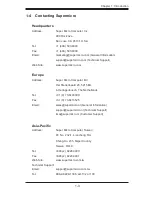
Page 1: ...SC846 CHASSIS SERIES USER S MANUAL 1 0 SC846TQ 900B SUPER...

Page 2: ...ive venue for the resolution of any such disputes Super Micro s total liability for all claims will not exceed the price paid for the hardware product FCC Statement This equipment has been tested and...

Page 3: ...t provides information for the installation and use of the SC846 chassis Installation and maintenance should be performed by experienced technicians only This document lists compatible parts available...

Page 4: ...details on this chassis model including the fans bays air ow shields and other components Chapter 4 System Interface Refer to this chapter for details on the system interface which includes the functi...

Page 5: ...with your chassis For complete information on supported cables and hardware refer to the Supermico Web site at www supermicro com Appendix B Power Supply Speci cations This chapter lists the speci cat...

Page 6: ...ttons 3 2 3 3 Control Panel LEDs 3 2 3 4 Drive Carrier LEDs 3 4 SAS SATA Drives 3 4 SCSI Drives 3 4 Chapter 4 Chassis Setup and Maintenance 4 1 Overview 4 1 4 2 Installation Step 1 Remove the Chassis...

Page 7: ...5 3 Preparing for Setup 5 1 Choosing a Setup Location 5 1 Rack Precautions 5 2 General Server Precautions 5 2 Rack Mounting Considerations 5 3 Ambient Operating Temperature 5 3 Reduced Air ow 5 3 Mech...

Page 8: ...mized cooling for FB DIMM memory modules and twenty four hot swap drive bays offer maximum storage capacity 1 2 Shipping List Part Numbers Please visit the following link for the latest shiping lists...

Page 9: ...o en sure the highest level of professional service and technical support we strongly recommend purchasing exclusively from our Supermicro Authorized Distributors System Integrators Resellers A list o...

Page 10: ...er Micro Computer B V Het Sterrenbeeld 28 5215 ML s Hertogenbosch The Netherlands Tel 31 0 73 6400390 Fax 31 0 73 6416525 Email sales supermicro nl General Information support supermicro nl Technical...

Page 11: ...846 Chassis Manual 1 4 Notes...

Page 12: ...for the rack unit that will hold that chassis It should be situated in a clean dust free area that is well venilated Avoid areas where heat electrical noise and eletromagnetic elds are generated You...

Page 13: ...orking with powered on electrical equipment This is to avoid making a complete circuit which will cause electrical shock Use extreme caution when using metal tools which can easily damage any electric...

Page 14: ...up and secure it to the rack unit with the retention screws after ensuring that all connections have been made 2 6 System Safety Electrostatic discharge ESD is generated by two objects with different...

Page 15: ...only do not touch its components peripheral chips memory modules or contacts When handling chips or modules avoid touching their pins Put the serverboard and peripherals back into their antistatic bag...

Page 16: ...ve carriers to keep you constantly informed of the overall status of the system as well as the activity and health of speci c components Most SC846 models are two buttons on the chassis control panel...

Page 17: ...servicing Reset The reset button is used to reboot the system 3 2 Control Panel Buttons There are two push buttons located on the front of the chassis These are in order from left to right a reset bu...

Page 18: ...upply units This LED should normally be illuminated when the system is operating HDD Indicates IDE channel activity SAS SATA drive SCSI drive and or DVD ROM drive activity when ashing NIC1 Indicates n...

Page 19: ...s being accessed Red The red LED to indicate an SAS SATA drive failure If one of the SAS SATA drives fail you should be noti ed by your system management software SCSI Drives Each SCSI drive carrier h...

Page 20: ...assis The only tool you will need to install components and perform maintenance is a Phillips screwdriver Print this chapter to use as a reference while setting up your chassis Review the warnings and...

Page 21: ...ce the top cover is released from the locked position slide the cover toward the rear of the chassis Lift the cover off the chassis 1 2 3 Warning Except for short periods of time do NOT operate the se...

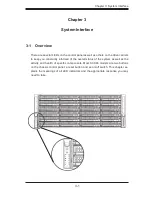
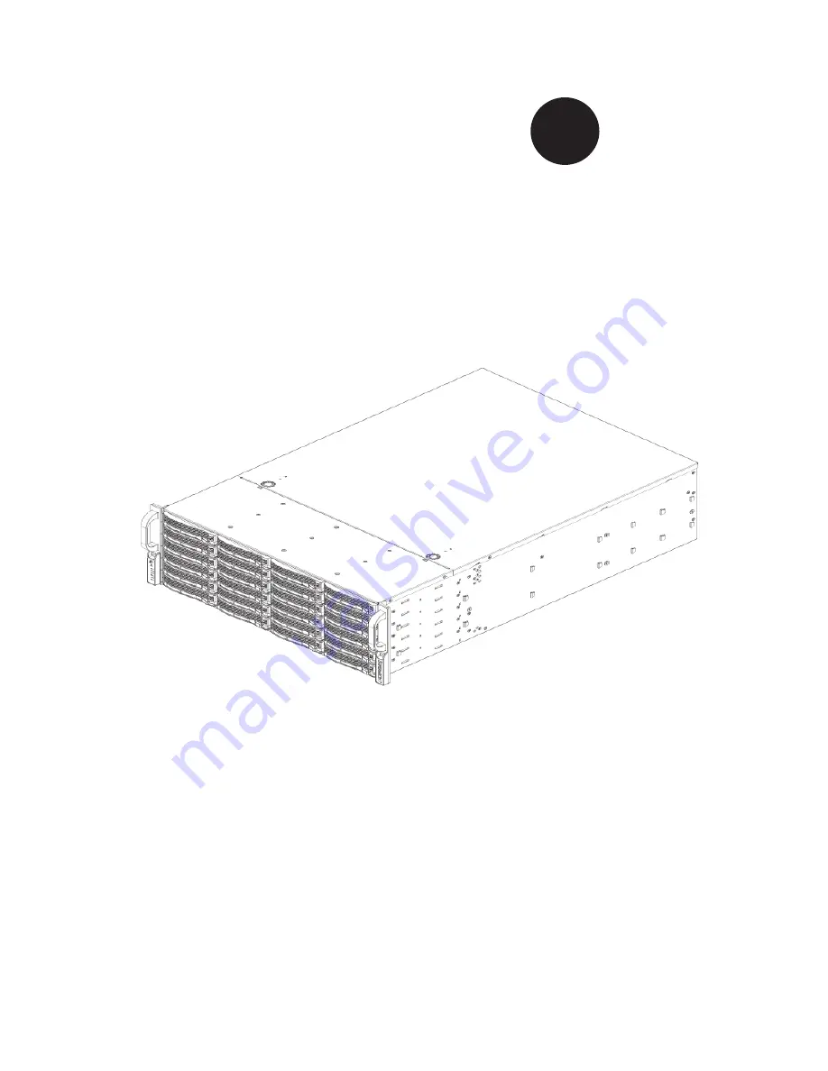
Page 22: ...4 3 Chapter 4 Chassis Setup and Maintenance Figure 4 2 Chassis Cover Removed...

Page 23: ...Step 2 Install Hard Drives To Remove Hard Drive Trays from the Chassis Press the release button on the drive tray This extends the drive bay handle Use the handle to pull the drive out of the chassis...

Page 24: ...assis Drive Tray To Install a Hard Drive to the Hard Drive Tray Remove the two screws securing the dummy drive to the drive tray and remove the dummy drive Place the hard drive tray on a at surface su...

Page 25: ...ng holes in both the drive tray and the hard drive Secure the hard drive to the tray using six screws Replace the drive tray into the chassis Make sure to close the drive tray handle to lock the drive...

Page 26: ...motherboard To Install the I O Shield Review the documentation that came with your motherboard Become familiar with component placement requirements and precautions Open the chassis cover With the il...

Page 27: ...hassis includes permanent standoffs in locations used by most motherboards These standoffs accept the rounded Phillips head screws included in the SC846 accessories packaging Some motherboards require...

Page 28: ...screws Secure the CPU s heatsinks and other components to the motherboard as described in the motherboard documentation 7 Connect the cables between the motherboard backplane chassis front panel and...

Page 29: ...tall Add on and Expansion Cards in SC846 Chassis Disconnect the power supply lay the chassis on a at surface and open the chassis cover Remove the screw holding the cover in place for each add on expa...

Page 30: ...ciency The SC846 chassis air shroud does not require screws to set up Figure 4 12 Air Shroud for SC846LP Chassis To Install the Air Shroud Con rm that your air shroud matches your chassis model Each s...

Page 31: ...e no wires or foreign objects obstruct air ow through the chassis Pull all excess cabling out of the air ow path or use shorter cables The control panel LEDs inform you of system status See Chapter 3...

Page 32: ...eriod of time with the chassis open 2 Turn off the power to the system and unplug the system from the outlet 3 Remove the failed fan s power cord from the serverboard 4 Press the fan release tab to li...

Page 33: ...846 Chassis Manual 4 14 Figure 4 15 Placing the Front System Fan Figure 4 16 Placing the Rear System Fan...

Page 34: ...utomatically sense and operate at a 100v to 240v input voltage An amber light will be illuminated on the power supply when the power is off An illuminated green light indicates that the power supply i...

Page 35: ...east two power mod ules you can leave the server running and remove only one power supply If your server has only one power supply you must power down the server and unplug the power cord 2 Push the r...

Page 36: ...out using the handle provided 4 Change the failed power module with the same model 5 Push the new power supply module into the power bay until you hear a click 6 Plug the AC power cord back into the...

Page 37: ...g Power down the server and remove the plug from the wall socket or power strip Remove all cable connections to the power supply from the motherboard backplane and other components Also remove both po...

Page 38: ...ousing Gently pull the power distributor and houseing from the chassis Carefully guide all the cables through the power distributor housing Remove the power distributor from the housing Slide the new...

Page 39: ...holding the drive into the HDD tray and set them aside These will be needed later to mount the replacement drive into the HDD tray 1 2 3 Note the locations of the CD ROM and DVD ROM and the space for...

Page 40: ...nd set them aside for later use when mounting the replacement HDD tray Remove the drive tray from the chassis Install the replacement HDD tray into the replacement drive tray using the four screws pre...

Page 41: ...acement drive into the replacement drive tray using the four screws and mylar washers previously set aside Using the four drive tray screws previously put aside install the replacement drive and drive...

Page 42: ...area that is well ventilated Avoid areas where heat electrical noise and electromagnetic elds are generated You will also need it placed near a grounded power outlet Be sure to read the Rack and Serv...

Page 43: ...rack You should extend only one component at a time extending two or more si multaneously may cause the rack to become unstable General Server Precautions Review the electrical and general safety prec...

Page 44: ...at the amount of air ow required for safe operation is not compromised Mechanical Loading Equipment should be mounted into a rack so that a hazardous condition does not arise due to uneven mechanical...

Page 45: ...edure will differ slightly You should also refer to the installation instructions that came with the rack unit you are using NOTE This rail will t a rack between 26 and 33 5 deep Identifying the Inner...

Page 46: ...side of the chassis aligning the hooks of the chas sis with the inner rail holes Make sure the rail faces outward so that it will t with the rack s mounting bracket Slide the rail toward the front of...

Page 47: ...the short and long brackets to the proper distance so that the rail ts snugly into the rack Secure the long bracket to the front side of the outer rail with two M5 screws and the short bracket to the...

Page 48: ...5 7 Chapter 5 Rack Installation Figure 5 4 Installing the Outer Rails to the Server Rack 3 3 2...

Page 49: ...n the rack Line chassis rails A and B with the front of the rack rails C Slide the chassis rails into the rack rails keeping the pressure even on both sides you may have to depress the locking tabs wh...

Page 50: ...e at www supermicro com A 2 Cables Included with SC846TQ Chassis SAS SATA SC846TQ R900 Part Type Length Description CBL 0157L Cable 9 8 pin to 8 pin ribbon cable for SGPIO PB free CBL 0087 Ribbon Roun...

Page 51: ...0175L Alt Name Big Four Alternate SAS SATA Cables Some compatible motherboards have different connectors If your motherboard has only one SAS connector that the SAS SATA cables must share use one of t...

Page 52: ...0 pin CBL 0059 7 9 20 CM 8 pin CBL 0062 7 9 20 CM 4 pin CBL 0060 7 9 20 CM Front Panel to the Motherboard The SCxxx chassis includes a cable to connect the chassis front panel to the motherboard If yo...

Page 53: ...M4 x 4 mm 0 157 RAIL Round head M4 x 4 mm 0 157 Flat head M5 x 12 mm 0 472 Washer for M5 DVD ROM CD ROM and FLOPPY DRIVE Flat head 6 32 x 5 mm 0 197 Pan head 6 32 x 5 mm 0 197 Round head M3 x 5 mm 0...

Page 54: ...ndix B Power Supply Speci cations Appendix B SC846 Power Supply Speci cations 900W MFR Part PWS 902 1R Rated AC Volt age 100 240V 50 60Hz 3 4 Amp 5V standby 4 Amp 12V 75 Amp 5V 50 Amp 3 3V 30 Amp 12V...

Page 55: ...SC846 Chassis Manual B 2 Notes...

Page 56: ...to prevent static discharge Touch a grounded metal object before removing a component from the antistatic bag Handle the RAID card by its edges only do not touch its components peripheral chips memor...

Page 57: ...A Note to Users All images and layouts shown in this user s guide are based upon the latest PCB Revision available at the time of publishing The card you have received may or may not look exactly the...

Page 58: ...T_SDOUT 3 JP94 I2CRST_SDOUT 4 2 3 I2C 1 2 SGPIO 1 2 SGPIO 2 3 I2C JP90 CTRL_ID 3 JP103 CTRL_ID 4 1 2 ID 0 2 3 ID 1 JP91 BP_ID 3 JP104 BP_ID 4 REV 1 01 SAS846TQ 4 S A S ACT FAIL C A C A ACT FAIL C A C...

Page 59: ...55 JP107 OH 3 TEMP 1 2 ID 0 2 3 ID 1 1 2 SGPIO 2 3 I2C JP123 BP_ID 5 JP126 BP_ID 6 JP122 CTRL_ID 5 JP125 CTRL_ID 6 ACT_IN 16 23 ACT_IN 8 15 ACT_IN 0 7 JP128 I2CRST_SDOUT 6 JP127 I2CRST_SDOUT 5 1 2 SGP...

Page 60: ...Header The activity LED header designated JP26 JP47 and JP108 is used to indicate the activ ity status of each SAS drive The Activity LED Header is located on the front panel For the Activity LED Hea...

Page 61: ...ed 0 23 Each port is also compatible with SATA drives 7 8 9 Sideband Headers The sideband headers are designated JP66 JP68 JP75 JP77 JP112 and JP114 For SES 2 to work properly you must connect an 8 pi...

Page 62: ...C A ACT FAIL C A C A ACT FAIL C A C A ACT FAIL C A C A ACT FAIL C A C A JP54 JP56 JP58 J22 J26 J29 J14 J16 J25 J23 J24 J30 J32 J39 J42 J48 J46 J40 J47 J41 J38 JP108 JP47 JP26 JP115 JP78 JP69 JP116 JP1...

Page 63: ...an Default 2 3 No Fan FAN 1 JP62 1 2 With Fan Default 2 3 No Fan FAN 2 JP98 1 2 With Fan Default 2 3 No Fan FAN 2 JP63 1 2 With Fan Default 2 3 No Fan FAN 3 JP99 1 2 With Fan Default 2 3 No Fan FAN 3...

Page 64: ...IO is the default mode and can be used without making changes to your jumper The following information details which jumper must be con gured to use SGPIO mode or restore your backplane to I2 C mode S...

Page 65: ...1 JP88 I2CRST_SDOUT 2 JP86 I2CRST 2 2 3 I2C JP83 I2CRST 1 1 2 SGPIO JP102 BP_ID 2 1 2 ID 0 JP85 BP_ID 1 2 3 ID 1 JP84 CTRL_ID 1 JP101 CTRL_ID 2 2 3 I2C 1 2 SGPIO JP74 BPID_SDIN 3 JP76 BPID_SDIN 4 1 2...

Page 66: ...JP77 JP66 5V 12V GND GND 5V 12V GND GND 1 1 3 1 3 1 3 2 3 NO FAN 1 2 WITH FAN JP61 FAN 1 SELECT JP64 FAN 4 SELECT JP63 FAN 3 SELECT JP62 FAN 2 SELECT JP124 I2CRST 6 2 3 I2C JP121 I2CRST 5 1 2 SGPIO J...

Page 67: ...2 D40 D37 SAS 3 D102 D107 SAS 4 D13 D6 SAS 5 D24 D29 SAS 6 D41 D38 SAS 7 D104 D108 SAS 8 D14 D7 SAS 9 D25 D30 SAS 10 D42 D39 SAS 11 D106 D109 SAS 12 D15 D8 SAS 13 D26 D31 SAS 14 D87 D88 SAS 15 D111 D...

Reviews: