background image

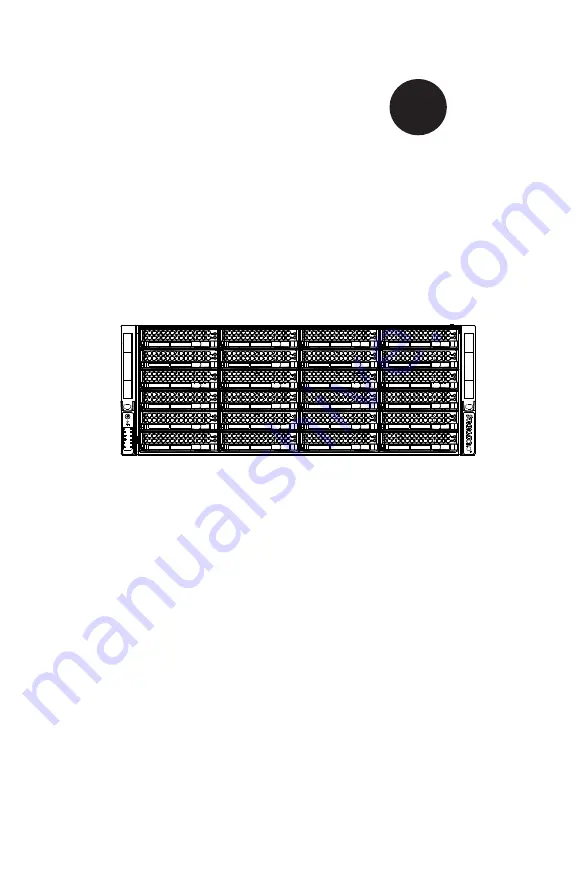
DOUBLE-SIDED STORAGE

SC847 CHASSIS SERIES

USER’S MANUAL 


1.0c


S

UPER

®

SC847A-R1400LPB

SC847A-R1400UB

SC847E1-R1400LPB

SC847E1-R1400UB

SC847E2-R1400LPB

SC847E2-R1400UB

SC847E16-R1400LPB

SC847E16-R1400UB

SC847E26-R1400LPB

SC847E26-R1400UB

SC847A-R1K28WB

SC847E16-R1K28WB

SC847E26-R1K28WB

SC847E16-R1K28LPB

SC847E26-R1K28LPB

Summary of Contents for SC847 Series

Page 1: ...c SUPER SC847A R1400LPB SC847A R1400UB SC847E1 R1400LPB SC847E1 R1400UB SC847E2 R1400LPB SC847E2 R1400UB SC847E16 R1400LPB SC847E16 R1400UB SC847E26 R1400LPB SC847E26 R1400UB SC847A R1K28WB SC847E16 R...

Page 2: ...ARE OR DATA STORED OR USED WITH THE PRODUCT INCLUDING THE COSTS OF REPAIRING REPLACING INTEGRATING INSTALLING OR RECOVERING SUCH HARDWARE SOFTWARE OR DATA Any disputes arising between manufacturer and...

Page 3: ...It provides information for the installation and use of the SC847 chassis Installation and maintenance should be performed by experienced technicians only This manual lists compatible parts available...

Page 4: ...tails on this chassis components including the fans hard drives air shrouds and other components Chapter 4 System Interface Refer to this chapter for details on the system interface which includes the...

Page 5: ...s For complete information on supported cables and hardware refer to the Supermico Web site at www supermicro com Appendix B Power Supply Specifications This chapter lists the specifications of the po...

Page 6: ...pment Installation 2 8 Restricted Area 2 9 Battery Handling 2 10 Redundant Power Supplies 2 12 Backplane Voltage 2 13 Comply with Local and National Electrical Codes 2 14 Product Disposal 2 15 Hot Swa...

Page 7: ...U Universal Output Chassis 5 11 5 8 Installing the Air Shroud 5 12 5 9 Checking the Server Air Flow 5 13 5 10 System Fans 5 14 5 11 Power Supply 5 16 Chapter 6 Rack Installation 6 1 Overview 6 1 6 2 U...

Page 8: ...4 Serial Connectivity for Increased Capacity 7 3 7 5 Serial Connectivity for Redundancy 7 4 7 6 Serial Connectivity for Redundancy Performance with Multiple PCI Buses 7 5 7 7 Supported Cascading Confi...

Page 9: ...se visit supermicro com for the latest shipping lists and part numbers for your chassis model Chapter 1 Introduction 1 1 SC847 Chassis Model HDD I O Slots Power Supply SC847A R1400LPB 36x Server SAS S...

Page 10: ...al If these are no longer available be sure to pack the chassis securely using packaging material to surround the chassis so that it does not shift within the carton and become damaged during shipping...

Page 11: ...dress Super Micro Computer B V Het Sterrenbeeld 28 5215 ML s Hertogenbosch The Netherlands Tel 31 0 73 6400390 Fax 31 0 73 6416525 Email sales supermicro nl General Information support supermicro nl T...

Page 12: ...SC847 Chassis Manual 1 4 Notes...

Page 13: ...nt for assistance Only certified technicians should attempt to install or configure components Read this appendix in its entirety before installing or configuring components in the Supermicro chassis...

Page 14: ...e los riesgos de la corriente el ctrica y familiar cese con los procedimientos est ndar de prevenci n de accidentes Al final de cada advertencia encontrar el n mero que le ayudar a encontrar el texto...

Page 15: ...l kan veroorzaken Voordat u aan enige apparatuur gaat werken dient u zich bewust te zijn van de bij een elektrische installatie betrokken risico s en dient u op de hoogte te zijn van de standaard proc...

Page 16: ...Systems an die Stromquelle die Installationsanweisungen lesen Advertencia Lea las instrucciones de instalaci n antes de conectar el sistema a la red de alimentaci n Attention Avant de brancher le sys...

Page 17: ...ert ist Stellen Sie sicher dass der Nennwert der Schutzvorrichtung nicht mehr als 250 V 20 A betr gt Advertencia Este equipo utiliza el sistema de protecci n contra cortocircuitos o sobrecorrientes de...

Page 18: ...ystemsbestandteile anzubringen oder zu entfernen Warning The system must be disconnected from all sources of power and the power cord removed from the power supply module s before accessing the chassi...

Page 19: ...nentes de sistema Attention Le syst me doit tre d branch de toutes les sources de puissance ainsi que de son cordon d alimentation secteur avant d acc der l int rieur du chassis pour installer ou enle...

Page 20: ...s Installieren Ersetzen oder Bedienen dieser Ausr stung sollte nur geschultem qualifiziertem Personal gestattet werden Advertencia Solamente el personal calificado debe instalar reemplazar o utilizar...

Page 21: ...stallation in Bereichen mit beschr nktem Zutritt vorgesehen Der Zutritt zu derartigen Bereichen ist nur mit einem Spezialwerkzeug Schloss und Schl ssel oder einer sonstigen Sicherheitsvorkehrung m gli...

Page 22: ...uivalent type recommended by the manufacturer Dispose of used batteries according to the manufacturer s instructions Waarschuwing Dit apparaat is bedoeld voor installatie in gebieden met een beperkte...

Page 23: ...ecommand e par le fabricant Jeter les piles usag es conform ment aux instructions du fabricant Advertencia Existe peligro de explosi n si la bater a se reemplaza de manera incorrecta Reemplazar la bat...

Page 24: ...ntes de alimentaci n Para cortar por completo el suministro de energ a deben desconectarse todas las conexiones Attention Cette unit peut avoir plus d une connexion d alimentation Pour supprimer toute...

Page 25: ...ero es peligroso Tenga cuidado cuando lo revise Attention Lorsque le syst me est en fonctionnement des tensions lectriques circulent sur le fond de panier Prendre des pr cautions lors de la maintenanc...

Page 26: ...codes Warnung Die Installation der Ger te muss den Sicherheitsstandards entsprechen Advertencia La instalacion del equipo debe cumplir con las normas de electricidad locales y nacionales Backplane Wa...

Page 27: ...ional laws and regulations Attention L quipement doit tre install conform ment aux normes lectriques nationales et locales Waarschuwing Bij installatie van de apparatuur moet worden voldaan aan de lok...

Page 28: ...odas las leyes y reglamentos nacionales Attention La mise au rebut ou le recyclage de ce produit sont g n ralement soumis des lois et ou directives de respect de l environnement Renseignez vous aupr s...

Page 29: ...dedos los destornilladores y todos los objetos lejos de las aberturas del ventilador Attention Il est possible que les ventilateurs soient toujours en rotation lorsque vous retirerez le bloc ventilat...

Page 30: ...ann zu einer Fehlfunktion oder ein Brand entstehen Elektrische Ger te und Material Safety Law verbietet die Verwendung von UL oder CSA zertifizierte Kabel UL oder CSA auf der Code f r alle anderen ele...

Page 31: ...utres appareils lectriques que les produits d sign s par Supermicro seulement AC AC UL CSA UL CSA UL CSA Supermicro UL CSA AC Electrical Appliance and Material Safety Law UL CSA UL CSA Waarschuwing Bi...

Page 32: ...2 20 SC847 Chassis Manual Notes...

Page 33: ...fers the option of up to four additional internal hard drives Power Supply The redundant power supply choices are 1280 Watt high efficiency 1 1 with PMBus 80 Plus Platinum certified 1400 Watt high eff...

Page 34: ...witch and an optional tray for mounting internal hard drives 3 3 Unpacking the System Inspect the box in which the chassis was shipped and note if it was damaged If the chassis itself shows damage fil...

Page 35: ...anel on the front edgre of the chassis and others on the drive carriers to help monitor the activity and status of the system and com ponents There are two buttons that control the system power This c...

Page 36: ...ning off system power with this button removes the main power but keeps standby power supplied to the system Therefore you must unplug system before servicing 4 2 Control Panel Buttons There are two p...

Page 37: ...ed in the table below Informational LED Status Description Continuously on and red An overheat condition has occured This may be caused by cable congestion Blinking red 1Hz Fan failure check for an in...

Page 38: ...ue LED When illuminated in a solid on state this blue LED on the front of the SAS SATA drive carrier indicates drive activity A connection to the SAS SATA backplane enables this LED to blink on and of...

Page 39: ...g Before performing any chassis setup or maintenance it is recom mended that the chassis be removed from the rack and placed on a stable bench or table For instructions on how to uninstall the chassis...

Page 40: ...If necessary unplug the chassis from any power source 2 Remove the screws securing the cover to the chassis 3 Lift the cover up and off the chassis Caution Except for short periods of time do not oper...

Page 41: ...ing Removable Hard Drives Removing Hard Drive Carriers from the Chassis 1 Press the release button on the drive carrier This extends the drive carrier handle 2 Use the handle to pull the drive carrier...

Page 42: ...Carrier Caution Enterprise level hard disk drives are recommended for use in Supermicro chassis and servers For information on recommended HDDs visit the Supermicro Web site at http www supermicro co...

Page 43: ...holes in both the drive carrier and the hard drive 4 Secure the hard drive to the carrier using six screws 5 Replace the drive tray into the chassis Make sure to close the drive carrier handle to loc...

Page 44: ...On the outside of the chassis remove the two screws securing the mother board tray to the chassis 3 On the inside of the chassis find the spring loaded pin that holds the mother board tray in the cha...

Page 45: ...g Dual 2 5 Hard Drives into the Bracket 1 Align the eight external tooth washers and eight screws with the holes in the hard drives and the holes in the bracket 2 Secure the hard drives to the bracket...

Page 46: ...with the hexagon nut rounded side up Installing the Motherboard 1 Review your motherboard documentation Become familiar with component placement requirements precautions and cable connections 2 Open t...

Page 47: ...ad screws Do not exceed eight inch pounds of torque 6 Secure the CPUs heatsinks and other components to the motherboard as described in the motherboard documentation 7 Connect the cables between the m...

Page 48: ...n card Figure 5 11 SC847 LP model Expansion Slot Setup in LP Low Profile Chassis Installing Expansion cards in an SC847 LP Chassis 1 Power down the system as described in Section 5 2 lay the chassis o...

Page 49: ...tput Card in the SC847 U Model Chassis 1 Power down the system as described in Section 5 2 lay the chassis on a flat surface and open the chassis cover 2 Connect the universal input output to the moth...

Page 50: ...tabs that allow the air shroud to be adjusted to fit a variety of motherboards Installing the Air Shroud 1 Power down the system as described in Section 5 2 and remove the cover 2 Place the air shrou...

Page 51: ...ommended server parts Make sure no wires or foreign objects obstruct air flow through the chassis Pull all excess cabling out of the airflow path or use shorter cables The control panel LEDs inform yo...

Page 52: ...period of time with the chassis cover open 2 Remove the failed fan s power cord from the serverboard 3 Press the fan release tab to lift the failed fan from the chassis and pull it completely out of t...

Page 53: ...5 15 Chapter 5 Chassis Setup and Maintenance Figure 5 14 Placing the System Fan...

Page 54: ...stem New units can be ordered directly from Supermicro see contact information in the Preface Changing the Power Supply 1 Unplug the AC cord from the module to be replaced Since your chassis includes...

Page 55: ...t 6 2 Preparing for Setup Decide on a suitable location for the rack unit that will hold your chassis It should be situated in a clean dust free area that is well ventilated Avoid areas where heat ele...

Page 56: ...ft in place as a precaution in case the test fails In any instance of pulling the system from the rack always use a rack lift and follow all associated safety precautions General Server Precautions Re...

Page 57: ...loading of circuits might have on overcurrent protection and power supply wiring Appropriate consideration of equipment nameplate ratings should be used when addressing this concern Reliable Ground A...

Page 58: ...ck between 26 5 and 36 4 deep Identifying the Sections of the Rack Rails The chassis package includes two rail assemblies in the rack mounting kit Each assembly consists of three sections An inner cha...

Page 59: ...the rack This prevents the server from coming completely out of the rack when when the chassis is pulled out for servicing Releasing the Inner Rail Releasing Inner Rail from the Outer Rails 1 Identify...

Page 60: ...ntified 2 Place the inner rail firmly against the side of the chassis aligning the hooks on the side of the chassis with the holes in the inner rail 3 Slide the inner rail forward toward the front of...

Page 61: ...k as illustrated above 4 Pull out the rear of the outer rail adjusting the length until it fits within the posts of the rack 5 Hang the hooks of the rear portion of the outer rail onto the slots on th...

Page 62: ...l the middle rail out from the front of the outer rail and make sure that the ball bearing shuttle is at the front locking position of the middle rail 4 Align the chassis inner rails with the front of...

Page 63: ...rear of the rack 7 If necessary for security purposes use screws to secure the chassis handles to the front of the rack Optional Quick Installation Method The following quick installation method may b...

Page 64: ...oks of the front of the outer rail into the square holes of one of the adapter brackets 2 Place the hooks of the rear of the outer rail into the square holes of a second adapter bracket 3 Adjust the l...

Page 65: ...SCOKET SEC_J2 SEC_J1 SEC_J0 PRI_J2 PRI_J1 PRI_J0 EC8 EC22 EC20 S_J1 P_J1 L1 SEC_MODE1 PRI_MODE1 SEC_IPMI1 PRI_IPMI1 PRI_I2C1 SEC_I2C1 J25 SEC_FLASH1 PRI_FLASH1 PRI_EXP1 SEC_EXP1 FAN2 FAN1 R227 BUZZER1...

Page 66: ...1 SEC_I2C1 J25 SEC_FLASH1 PRI_FLASH1 PRI_EXP1 SEC_EXP1 FAN2 FAN1 R227 BUZZER1 5V_LED1 OVERHEATFAIL1 FANFAIL1 BUZZER_ENB1 REMOTE_FAN_FAIL_SOCKET1 PWR6 PWR4 PWR5 PWR3 PWR2 PWR1 BAR CODE 2 A C A C A C A...

Page 67: ...R199 R227 R210 BUZZER1 5V_LED1 OVERHEATFAIL1 FANFAIL1 BUZZER_ENB1 REMOTE_FAN_FAIL_SOCKET1 PWR6 PWR4 PWR5 PWR3 PWR2 PWR1 BAR CODE 2 A C A C A C A C 5V 12V GND GND 5V 12V GND GND 5V 12V GND GND 5V 12V...

Page 68: ...WWN DESIGNED IN USA REV 1 01 SAS846EL2 1J24 2 SEC_J2 SEC_J1 SEC_J0 PRI_J2 PRI_J1 PRI_J0 EC8 EC22 EC20 S_J1 P_J1 L1 SEC_MODE1 PRI_MODE1 SEC_IPMI1 PRI_IPMI1 PRI_I2C1 SEC_I2C1 J25 SEC_FLASH1 PRI_FLASH1...

Page 69: ...PRI_EXP1 SEC_EXP1 FAN2 FAN1 R199 R227 R210 BUZZER1 5V_LED1 OVERHEATFAIL1 FANFAIL1 BUZZER_ENB1 REMOTE_FAN_FAIL_SOCKET1 PWR6 PWR4 PWR5 PWR3 PWR2 PWR1 BAR CODE 2 A C A C A C A C 5V 12V GND GND 5V 12V GN...

Page 70: ...n the cables utilized in the preceding cascading configurations Backplane Connectivity Cables Part Number Length Description CBL 0281L 75cm SFF 8087 to SFF 8087 internal backplane cable CBL 0351L LP 8...

Page 71: ...les refer to the manufacturer of the motherboard you are using and our Web site at www supermicro com A 2 Cables Included with SC847 Chassis SAS SATA SC847 Part Type Length Description CBL 0088L Cable...

Page 72: ...0175L Alt Name Big Four Alternate SAS SATA Cables Some compatible motherboards have different connectors If your motherboard has only one SAS connector that the SAS SATA cables must share use one of...

Page 73: ...0 pin CBL 0059 7 9 20cm 8 pin CBL 0062 7 9 20cm 4 pin CBL 0060 7 9 20cm Front Panel to the Motherboard The SC847 chassis includes a cable to connect the chassis front panel to the motherboard If your...

Page 74: ...M4 x 4 mm 0 157 RAIL Round head M4 x 4 mm 0 157 Flat head M5 x 12 mm 0 472 Washer for M5 DVD ROM CD ROM and FLOPPY DRIVE Flat head 6 32 x 5 mm 0 197 Pan head 6 32 x 5 mm 0 197 Round head M3 x 5 mm 0...

Page 75: ...5 13 5A 1400W 180 240V 50 60Hz 7 0 9 5A DC Output 5V Standby 4A DC Output 12V 92A 100 140V 116Ap 180 240V With Distributor 5V 30A 3 3V 24A 12V 0 6Ap Certification 80 Plus Gold level 1280 Watt Redundan...

Page 76: ...SC847 Chassis Manual B 2 Notes...

Page 77: ...ic discharge Touch a grounded metal object before removing a component from the antistatic bag Handle the backplane by its edges only do not touch its components peripheral chips memory modules or gol...

Page 78: ...cs shown in this manual C 4 Introduction to the SAS 826A Backplane The SAS 826A backplane has been designed to utilize the most up to date technol ogy available providing your system with reliable hig...

Page 79: ...2 U24 U41 JP69 JP78 RP1 U2 JP26 JP47 U18 BAR CODE B B SAS IN 1 SAS IN 2 9072 RST 9071 RST ACT4 ACT11 ACT10 ACT9 ACT8 ACT3 ACT2 ACT1 ACT7 ACT6 ACT5 ACT0 2 3 I2C 1 2 SGPIO JP84 MODE C 2 3 55 1 2 50 C C...

Page 80: ...tus of each SAS drive The activity LED headers are located on the front panel For the activity lead headers to work properly connect to them using a 10 pin LED cable This is only used when the activit...

Page 81: ...designated JP10 JP13 and JP46 provide power to the backplane See the table on the right for pin definitions 7 8 9 SAS Ports The SAS ports are used to connect the SAS drive cables The 12 ports are desi...

Page 82: ...DE C 2 3 55 1 2 50 C C OPEN 45 JP45 OH 2 TEMP C C C 2 3 55 1 2 50 OPEN 45 JP25 OH 1 TEMP ALARM 1 ALARM 2 ACT_IN 8 11 ACT_IN 0 7 UPGRADE 2 UPGRADE 1 SAS IN 3 I2C 3 I2C 2 I2C 1 BUZZER RESET REV 1 00 SAS...

Page 83: ...84 1 2 SGPIO mode enable C 3 I2 C mode enable I2 C and SGPIO Modes and Jumper Settings This backplane can utilize I2 C or SGPIO SGPIO is the default mode and can be used without making changes to your...

Page 84: ...6 R132 JP25 1 JP45 1 JP84 JP37 JP95 JP52 U24 U41 JP69 JP78 RP1 U2 JP26 JP47 U18 BAR CODE B B SAS IN 1 SAS IN 2 9072 RST 9071 RST ACT4 ACT11 ACT10 ACT9 ACT8 ACT3 ACT2 ACT1 ACT7 ACT6 ACT5 ACT0 2 3 I2C 1...

Page 85: ...FAIL 0 C 8 Rear Connectors and LED Indicators Rear SAS SATA Connectors Rear Connector SAS Drive Number Rear Connector SAS Drive Number SAS 0 SAS SATA HHD 0 SAS 6 SAS SATA HHD 6 SAS 1 SAS SATA HHD 1 SA...

Page 86: ...C 10 SC847 Chassis Manual Notes...

Page 87: ...revent static discharge Touch a grounded metal object before removing a component from the antistatic bag Handle the backplane by its edges only do not touch its components peripheral chips memory mod...

Page 88: ...wn in this manual D 4 Introduction to the SAS 846A Backplane The SAS 846A backplane has been designed to utilize the most up to date technol ogy available providing your system with reliable high qual...

Page 89: ...NO RESET 1 2 RESET 2 3 NO RESET 1 2 RESET 22 23 20 21 18 19 16 17 14 15 12 13 10 11 8 9 6 7 4 5 3 2 1 0 JP129 9072 3 RESET JP35 9072 1 RESET JP50 9072 2 RESET BUZZER RESET 2 3 NO FAN 1 2 WITH FAN JP6...

Page 90: ...ity LED Header is located on the front panel For the Activity LED Header to work properly connect using a 10 pin LED cable 4 5 6 I2 C Connectors The I2 C Connectors designated JP37 JP95 JP52 JP96 JP11...

Page 91: ...3 JP62 1 3 JP61 JP50 1 3 JP35 1 JP129 1 3 JP107 1 3 JP97 JP98 JP99 JP45 JP25 JP100 JP18 F4 D54 A C D53 A C D36 A C D3 A C D51 A C D49 A C D47 A C D45 A C D89 A C C85 C84 C5 C45 C44 C3 C204 C203 C202...

Page 92: ...No Fan FAN 2 JP63 1 2 With Fan Default 2 3 No Fan FAN 3 JP99 1 2 With Fan Default 2 3 No Fan FAN 3 JP64 1 2 With Fan Default 2 3 No Fan FAN 4 JP100 1 2 With Fan Default 2 3 No Fan FAN 4 I2 C and SGPIO...

Page 93: ...00 JP18 F4 D54 A C D53 A C D36 A C D3 A C D51 A C D49 A C D47 A C D45 A C D89 A C C85 C84 C5 C45 C44 C3 C204 C203 C202 C201 C200 C199 C198 C197 C119 C285 C330 C329 C328 C327 C326 C325 C324 C323 C283 C...

Page 94: ...IL 16 21 20 19 18 12 13 14 15 9 8 7 6 3 2 1 0 SAS SAS SAS SAS SAS SAS SAS SAS SAS SAS SAS SAS SAS SAS SAS SAS FAIL 12 ACT 12 ACT 8 FAIL 8 ACT 4 FAIL 4 ACT 0 FAIL 0 D 8 Rear Connectors and LED Indicato...

Page 95: ...SAS 2 D14 D7 SAS 3 D15 D8 SAS 4 D18 D19 SAS 5 D21 D20 SAS 6 D22 D23 SAS 7 D24 D29 SAS 8 D25 D30 SAS 9 D26 D31 SAS 10 D27 D32 SAS 11 D28 D33 SAS 12 D40 D37 SAS 13 D41 D38 SAS 14 D42 D39 SAS 15 D87 D88...

Page 96: ...D 10 SC847 Chassis Manual Notes...

Page 97: ...D Use a grounded wrist strap designed to prevent static discharge Touch a grounded metal object before removing a component from the antistatic bag Handle the backplane by its edges only do not touch...

Page 98: ...hics shown in this manual E 4 Introduction to the SAS 826EL Backplane The SAS 826EL backplane has been designed to utilize the most up to date technol ogy available providing your system with reliable...

Page 99: ...ailable in EL1 single port backplane E 5 Front Connectors and Jumpers 2 1 1 2 3 1 1 3 A C A C A C 1 GND GND 12V 5V GND GND 12V 5V GND GND 12V 5V BAR CODE WWN SAS826EL REV 1 02 DESIGNED IN USA WWN OVER...

Page 100: ...Connectors The 4 pin connectors designated PWR0 PWR1 and PWR3 provide power to the backplane See the table on the right for pin definitions 5 Fan Connectors The 3 pin connectors designated Fan1 Fan2...

Page 101: ...the backplane jumpers can be used to choose between optional settings Jumpers create shorts between two pins to change the function of the connector Pin 1 is identified with a square solder pad on th...

Page 102: ...gs Socket Socket Setting Note REMOTE_FAN_FAIL_ SOCKET Open Front panel fan fail indicator optional General Jumper Settings Jumper Jumper Settings Note PRI_MODE4 1 2 Factory setting do not change SEC_M...

Page 103: ...is on during normal operation Front LED Indicators Fan Fail LED 2 1 1 2 3 1 1 3 A C A C A C 1 GND GND 12V 5V GND GND 12V 5V GND GND 12V 5V BAR CODE WWN SAS826EL REV 1 02 DESIGNED IN USA WWN OVERHEATFA...

Page 104: ...SAS 11 SAS HDD 11 Rear LED Indicators Rear LED Hard Drive Activity Failure LED SAS 0 ACT 0 FAIL 0 SAS 1 ACT 1 FAIL 1 SAS 2 ACT 2 FAIL 2 SAS 3 ACT 3 FAIL 3 SAS 4 ACT 4 FAIL 4 SAS 5 ACT 5 FAIL 5 SAS 6...

Page 105: ...le and Dual Port Expanders Single Ports SAS 826EL1 backplanes have a single port expander that access all twelve drives and supports cascading Dual Ports SAS 826EL2 backplanes have dual port expanders...

Page 106: ...he system will automatically fail over to Port B Dual Host Bus Adapter In a dual host bus configuration the backplane connects to two host bus adapters Dual Host Bus Adapter Failover If the expander o...

Page 107: ...ascaded configuration the first chassis includes a motherboard and at least one host bus adapter Other servers in this enclosed system include a power card This section describes the supported power c...

Page 108: ...lane The following section lists the most common cables used to connect the HBA to the backplane HBA Host Bus Adapter HBA Host Bus Adapter HBA Host Bus Adapter Single Internal Host Bus Adapter Dual In...

Page 109: ...ength 22 cm 9 inches Part CBL 0110L 02 Length 18 cm 7 inches Description This cable has one SFF 8484 32 pin connector on one end and ipass SFF 8087 Mini SAS connector 36 pins at the other This cable c...

Page 110: ...e in different physical chassis This allows a JBOD Just a Bunch Of Drives configuration from an existing system HBA Host Bus Adapter Power Card Single External Host Bus Adapter HBA Host Bus Adapter Po...

Page 111: ...he following cable if your external HBA has an InfiniBand connector Description This cable has an InfiniBand connector SFF 8470 on one end and an SFF 8088 1X 26 pins at the other end Cable Name SAS In...

Page 112: ...A Host Bus Adapter Power Card Single HBA Configuration Connecting Multiple Backplanes in a Single Channel Environment This section describes the cables used when cascading from a single HBA These conn...

Page 113: ...0166L SFF 8088 1x to SFF 8088 x1 Ports Single or Dual Placement External cable Description Internal cable Connects the backplane to the Host Bus Adapter HBA or external port Used in single port enviro...

Page 114: ...iple Backplanes in a Dual Channel Environment This section describes the cables used when cascading from a single HBA These connections use CBL 0168L internal cables and CBL 0166L external cables Powe...

Page 115: ...o SFF 8088 x2 Ports Dual Placement Internal cable Description External cascading cable Connects ports between servers Use one cable for single port connections and two cables for dual port connections...

Page 116: ...scaded system requires a motherboard and HBA Other servers require a power control card not a motherboard and HBA Other Considerations Cascading supports up to one hundred twenty two hard drives Use t...

Page 117: ...L Backplane Specifications Server System with Dual SAS HBA and Cascading Configuration CBL 0166L External cable CBL 0168L with Dual Port Assembly internal cable Power Card HBA Host Bus Adapter HBA Hos...

Page 118: ...E 22 SC847 Chassis Manual Notes...

Page 119: ...prevent static discharge Touch a grounded metal object before removing a component from the antistatic bag Handle the backplane by its edges only do not touch its components peripheral chips memory mo...

Page 120: ...shown in this manual F 4 Introduction to the SAS 846EL Backplane The SAS 846EL backplane has been designed to utilize the most up to date technol ogy available providing your system with reliable hig...

Page 121: ...FANFAIL1 BUZZER_ENB1 REMOTE_FAN_FAIL_SOCKET1 PWR6 PWR4 PWR5 PWR3 PWR2 PWR1 BAR CODE 2 A C A C A C A C 5V 12V GND GND 5V 12V GND GND 5V 12V GND GND 5V 12V GND GND 5V 12V GND GND 5V 12V GND GND WWN WWN...

Page 122: ...itions Backplane Main Power 4 Pin Connector Pin Definition 1 12V 2 and 3 Ground 4 5V 3 Backplane Main Power Connectors The 4 pin connectors designated PWR1 PWR2 PWR3 PWR4 PWR5 and PWR6 provide power t...

Page 123: ...provide power to the fans See the table on the right for pin definitions Fan Connectors Pin Definition 1 Ground 2 12V 3 Tachometer 8 13 SAS Ports The primary and secondary sets of SAS ports provide e...

Page 124: ...1 R227 BUZZER1 5V_LED1 OVERHEATFAIL1 FANFAIL1 BUZZER_ENB1 REMOTE_FAN_FAIL_SOCKET1 PWR6 PWR4 PWR5 PWR3 PWR2 PWR1 BAR CODE 2 A C A C A C A C 5V 12V GND GND 5V 12V GND GND 5V 12V GND GND 5V 12V GND GND 5...

Page 125: ...d Front Panel Fan Fail indicator Optional General Jumper Settings Jumper Jumper Settings Note PRI_MODE1 1 2 Factory Setting Do not change SEC_MODE1 1 2 Factory Setting Do not change Front Panel LEDs L...

Page 126: ...ACT4 ACT5 ACT7 ACT8 ACT9 ACT10 ACT11 ACT12 ACT13 ACT14 ACT15 FAIL4 FAIL5 FAIL6 FAIL7 FAIL8 FAIL9 FAIL10 FAIL11 FAIL12 FAIL13 FAIL14 FAIL0 FAIL1 FAIL2 FAIL3 FAIL15 J23 J22 J21 J18 J19 J20 J17 J16 J13 J...

Page 127: ...FAIL 4 SAS 5 ACT 5 FAIL 5 SAS 6 ACT 6 FAIL 6 SAS 7 ACT 7 FAIL 7 SAS 8 ACT 8 FAIL 8 SAS 9 ACT 9 FAIL 9 SAS 10 ACT 10 FAIL 10 SAS 11 ACT 11 FAIL 11 SAS 12 ACT 12 FAIL 12 SAS 13 ACT 13 FAIL 13 SAS 14 ACT...

Page 128: ...L1 backplanes have a single port expander that access all twenty four drives and supports cascading Dual Ports SAS 846EL2 backplanes have dual port expanders that access all twenty four drives These d...

Page 129: ...Bus Adapter Failover If the expander or data path in Port A fails the system automatically switches to Port B Figure F 7 Single HBA Failover PRI_J0 PRI_J1 PRI_J2 SEC_J0 SEC_J1 SEC_J2 J17 WWN SAS HBA...

Page 130: ...a cascaded configuration the first chassis includes a motherboard and at least one Host Bus Adapter HBA Other servers in this enclosed system include a power card This section describes the supported...

Page 131: ...orted Internal HBA Cables Use the following listed cables to create connections between the internal HBA and SAS 846EL backplane The cables required depend on the HBA connector HBA Host Bus Adapter PR...

Page 132: ...FF 8087 mini SAS connector 36 pins at each end It connects from the HBA to the SAS 846EL backplane Cable Name iPass mini SAS to iPass mini SAS Part CBL 0108L 02 Length 39 cm 15 inches Part CBL 0109L 0...

Page 133: ...configura tion system to connect to the other system that has a HBA HBA Host Bus Adapter Power Card HBA Host Bus Adapter Dual External Host Bus Adapter CBL 0200L External HBA Cables HBA Host Bus Adapt...

Page 134: ...if your external HBA has an InfiniBand connector Description This cable has an InfiniBand connector SFF 8470 on one end and an SFF 8088 1X 26 pins at the other end Cable Name SAS InfiniBand to Mini S...

Page 135: ...J17 WWN Port B Expander 2 Power Card PRI_J0 PRI_J1 PRI_J2 SEC_J0 SEC_J1 SEC_J2 J17 WWN Port B Expander 2 Port A Expander 1 Connecting Multiple Backplanes in a Single Channel Environment This section d...

Page 136: ...8088 x1 Ports Single or Dual Placement External cable Description Internal cable Connects the backplane to the Host Bus Adapter HBA or external port Used in single port environments Cable Name SAS EL2...

Page 137: ...nder 2 Power Card PRI_J0 PRI_J1 PRI_J2 SEC_J0 SEC_J1 SEC_J2 J17 WWN Port A Expander 1 Port B Expander 2 Cable 0168L with Single Port Assembly Internal cable Connecting Multiple Backplanes in a Dual Ch...

Page 138: ...ual Placement Internal cable Description External cascading cable Connects ports between servers Use one cable for single port connections and two cables for dual port connections Cable Name SAS EL2 E...

Page 139: ...information see the SC846 Chassis Manual available at www supermicro com F 12 Supported Cascading Configurations Cable 0167L internal cable Cable 0166L external cable Single Port Cable Assembly HBA H...

Page 140: ...Card PRI_J0 PRI_J1 PRI_J2 SEC_J0 SEC_J1 SEC_J2 J17 WWN Port A Expander 1 Power Card PRI_J0 PRI_J1 PRI_J2 SEC_J0 SEC_J1 SEC_J2 J17 WWN Port A Expander 1 Power Card PRI_J0 PRI_J1 PRI_J2 SEC_J0 SEC_J1 S...

Page 141: ...B Expander 2 Power Card PRI_J0 PRI_J1 PRI_J2 SEC_J0 SEC_J1 SEC_J2 J17 WWN Port A Expander 1 Power Card PRI_J0 PRI_J1 PRI_J2 SEC_J0 SEC_J1 SEC_J2 J17 WWN Port A Expander 1 Cable 0168L internal cable Du...

Page 142: ...Ex 2 Port A Ex 1 Power Card Port B Ex 2 Port A Ex 1 Power Card Port B Ex 2 Port A Ex 1 Port A Ex 1 Power Card Port B Ex 2 Port A Ex 1 Power Card Port B Ex 2 Port A Ex 1 Figure F 25 Dual SAS HBA with C...

Page 143: ...ESD Use a grounded wrist strap designed to prevent static discharge Touch a grounded metal object before removing a component from the antistatic bag Handle the backplane by its edges only do not tou...

Page 144: ...liable high quality performance This manual reflects BPN SAS2 826EL Revision 1 01 the most current release available at the time of publication Always refer to the Supermicro Web site at www supermicr...

Page 145: ...8 503 8008 SILKSCREEN PRIMARY SIDE SUPER R SUPER SUPER SUPER SUPER SUPER SUPER SUPER SUPER SUPER SUPER SUPER SUPER SUPER SUPER SUPER SUPER SUPER R R R R R R R R R R WWN WWN AB AA DESIGNED IN USA REV 1...

Page 146: ...definitions Fan Connectors Pin Definition 1 Ground 2 12V 3 Tachometer 2 Primary and Secondary Expander Chips This primary and secondary expander chips allow the backplane to support dual port cas cad...

Page 147: ...IMENSIONS UNLESS OTHERWISE XXX XX X 010 03 1 TOLERANCES DECIMAL ARE IN INCHES Teddy Ben DESINGER DATE 2009 12 15 PROJECT NAME SAN JOSE CA 95131 DESIGNED BY SUPERMICRO U S A www supermicro com TEL 408...

Page 148: ...N_MONITOR_DIS ABLE Open Enabled Default Closed Disabled Enables the fan speed monitor reporting FANFAIL_LED_DIS ABLE Open Enabled Default Closed Disabled Enables the FANFAIL1 LED BUZZER_ENB1 Open Disa...

Page 149: ...6 MH5 MH4 4 1 FAN1 4 FAN2 1 FAN3 1 8 J18 1 8 5 Y E 20 R K 10 15 AE 25 28 AH 5 E 20 R K 10 15 AE 25 28 AH SEC_MODE1 1 3 1 SEC_MODE2 1 3 Y2 1 4 EXPDBG1 1 EXPDBG2 1 4 UART_S1 1 4 UART_P1 PRI_MODE1 PRI_MO...

Page 150: ...R S U P E R S U P E R S U P E R S U P E R S U P E R S U P E R S U P E R S U P E R S U P E R S U P E R S U P E R S U P E R R R R R R R R R R R G 10 Rear Connectors and LED Indicators Rear SAS Connector...

Page 151: ...DISABLE 1 BUZZER_ENB1 1 MDIO1 MDIO2 1 ACTLED1 FAN_MONITOR_DISABLE 1 MH9 MH8 MH7 MH6 MH5 MH4 4 1 FAN1 4 FAN2 1 FAN3 1 8 J18 1 8 5 Y E 20 R K 10 15 AE 25 28 AH 5 E 20 R K 10 15 AE 25 28 AH SEC_MODE1 1 3...

Page 152: ...408 503 8008 SILKSCREEN PRIMARY SIDE SUPER R SUPER SUPER SUPER SUPER SUPER SUPER SUPER SUPER SUPER SUPER SUPER SUPER SUPER SUPER SUPER SUPER SUPER R R R R R R R R R R WWN WWN AB AA DESIGNED IN USA RE...

Page 153: ...5 C353 C352 C134 C133 C132 C121 C120 C119 EC19 R167 2 1 J16 J19 PRI_J1 PRI_J0 SEC_J0 SEC_J1 BC8 BC518 C157 C395 1 FANFAIL_LED_DISABLE 1 BUZZER_ENB1 1 MDIO1 MDIO2 1 ACTLED1 FAN_MONITOR_DISABLE 1 MH9 MH...

Page 154: ...escribes the supported power card for the BPN SAS2 826EL backplane system C38 Q1 BUZZER1 J1 1 12 13 24 R31 R24 R22 R23 R19 R4 R14 R11 R1 R2 R12 R16 R13 R7 R3 R15 R5 R6 R8 R17 R92 R93 R94 R18 R20 R21 R...

Page 155: ...R R R R R WWN WWN AB AA DESIGNED IN USA REV 1 01 BPN SAS2 826EL2 HBA HBA HBA Q9 F1 FANFAIL1 A C OVERHEATFAIL1 A C 5V_LED1 A C 12V_LED1 A C ACT18 A C ACT17 A C C367 C366 C365 C353 C352 C134 C133 C132 C...

Page 156: ...9 inches Part CBL 0110L 02 Length 18 cm 7 inches Description This cable has one SFF 8484 32 pin connector on one end and one iPass SFF 8087 Mini SAS connector 36 pin at the other This cable connects f...

Page 157: ...SUPER SUPER SUPER R R R R R R R R R R WWN WWN AB AA DESIGNED IN USA REV 1 01 BPN SAS2 826EL2 Single External Host Bus Adapter HBA Power Card Q9 F1 FANFAIL1 A C OVERHEATFAIL1 A C 5V_LED1 A C 12V_LED1...

Page 158: ...if your external HBA has an InfiniBand connector Description This cable has an InfiniBand connector SFF 8470 on one end and an SFF 8088 1X 26 pin connector at the other end Cable Name SAS InfiniBand...

Page 159: ...CRO U S A www supermicro com TEL 408 503 8000 FAX 408 503 8008 SILKSCREEN PRIMARY SIDE SUPER R SUPER SUPER SUPER SUPER SUPER SUPER SUPER SUPER SUPER SUPER SUPER SUPER SUPER SUPER SUPER SUPER SUPER R R...

Page 160: ...088 1x to SFF 8088 x1 Ports Single or Dual Placement External cable Description Internal cable Connects the backplane to the host bus adapter or external port Used in single port environments Cable Na...

Page 161: ...ER SUPER SUPER SUPER SUPER SUPER SUPER SUPER SUPER SUPER SUPER SUPER SUPER SUPER SUPER SUPER R R R R R R R R R R WWN WWN AB AA DESIGNED IN USA REV 1 01 BPN SAS2 826EL2 HBA HBA Q9 F1 FANFAIL1 A C OVERH...

Page 162: ...ts Dual Placement Internal cable Description External cascading cable Connects ports between servers Use one cable for single port connections and two cables for dual port connections Cable Name BPN S...

Page 163: ...19 PRI_J1 PRI_J0 SEC_J0 SEC_J1 BC8 BC518 C157 C395 1 FANFAIL_LED_DISABLE 1 BUZZER_ENB1 1 MDIO1 MDIO2 1 ACTLED1 FAN_MONITOR_DISABLE 1 MH9 MH8 MH7 MH6 MH5 MH4 4 1 FAN1 4 FAN2 1 FAN3 1 8 J18 1 8 5 Y E 20...

Page 164: ...187 JP1 1 4 C408 BCA115 BCA121 C265 C72 R305 C128 C130 C362 EC6 EC10 EC11 EC12 EC13 EC14 EC18 EC7 EC8 EC9 5V 12V GND GND PWR1 5V 12V GND GND PWR2 5V 12V GND GND PWR3 SAS CODE BAR CODE 1 00 REV BPN SAS...

Page 165: ...prevent static discharge Touch a grounded metal object before removing a component from the antistatic bag Handle the backplane by its edges only do not touch its components peripheral chips memory m...

Page 166: ...viding your system with reliable high quality performance This manual reflects SAS2 846EL1 and SAS2 846EL2 PCB Revision 1 10 the most current release available at the time of publication Always refer...

Page 167: ...GND PWR1 1 01 REV BPN SAS2 846EL2 MACH FINISH 30 ANGLE SPECIFIED DIMENSIONS UNLESS OTHERWISE XXX XX X 010 03 1 TOLERANCES DECIMAL ARE IN INCHES Minh Max DESINGER DATE 2009 12 09 PROJECT NAME SAN JOSE...

Page 168: ...nitions Backplane Main Power 4 Pin Connector Pin Definition 1 12V 2 and 3 Ground 4 5V 2 Backplane Main Power Connectors The 4 pin connectors designated PWR1 PWR2 PWR3 PWR4 PWR5 and PWR6 provide power...

Page 169: ...ght for pin defini tions Fan Connectors Pin Definition 1 Ground 2 12V 3 Tachometer 7 13 SAS Connectors The primary and secondary sets of SAS connectors provide expander features in cluding cascading a...

Page 170: ...WR2 5V 12V GND GND PWR1 1 01 REV BPN SAS2 846EL2 MACH FINISH 30 ANGLE SPECIFIED DIMENSIONS UNLESS OTHERWISE XXX XX X 010 03 1 TOLERANCES DECIMAL ARE IN INCHES Minh Max DESINGER DATE 2009 12 09 PROJECT...

Page 171: ...nnector Not present on SAS2 847E2 JP1 No jumper required Buzzer connector BUZZER_ENB1 Open Disabled Default Closed Enabled Buzzer settings ACTLED1 Open Disabled Default Closed Enabled Activity LED set...

Page 172: ...3 ACT 2 FAIL 2 ACT 7 FAIL 7 ACT 6 FAIL 6 1 SAS 0 SAS 6 SAS 7 SAS 13 SAS SAS 12 ACT 12 FAIL 12 FAIL 13 ACT 13 ACT 18 FAIL 18 ACT 19 FAIL 19 SAS 18 SAS 19 ACT 23 FAIL 23 ACT 22 FAIL 22 ACT 21 FAIL 21 FA...

Page 173: ...FAIL 4 SAS 5 ACT 5 FAIL 5 SAS 6 ACT 6 FAIL 6 SAS 7 ACT 7 FAIL 7 SAS 8 ACT 8 FAIL 8 SAS 9 ACT 9 FAIL 9 SAS 10 ACT 10 FAIL 10 SAS 11 ACT 11 FAIL 11 SAS 12 ACT 12 FAIL 12 SAS 13 ACT 13 FAIL 13 SAS 14 ACT...

Page 174: ...BUZZER_ENB1 1 REMOTE_FAN_FAIL_SCOKET 1 MDIO2 1 MDIO1 F3 F1 FANFAIL1 A C OVERHEATFAIL1 A C 12V_LED A C 5V_LED A C ACT25 A C ACT24 A C D7 BCA376 C367 C125 Q9 PRI_MODE1 1 3 SEC_MODE1 3 SEC_MODE2 1 3 PRI...

Page 175: ...SAS2 846EL2 backplane has two expanders which allow effective failover H 11 Failover Single Host Bus Adapter Failover If the expander or data path in the primary ports fails the system automati cally...

Page 176: ...scribes the supported power card for the SAS2 846EL series backplanes C38 Q1 BUZZER1 J1 1 12 13 24 R31 R24 R22 R23 R19 R4 R14 R11 R1 R2 R12 R16 R13 R7 R3 R15 R5 R6 R8 R17 R92 R93 R94 R18 R20 R21 R70 F...

Page 177: ...FAIL1 1 BUZZER_ENB1 1 REMOTE_FAN_FAIL_SCOKET 1 MDIO2 1 MDIO1 F3 F1 FANFAIL1 A C OVERHEATFAIL1 A C 12V_LED A C 5V_LEDA C ACT25 A C ACT24 A C D7 BCA376 C367 C125 Q9 PRI_MODE1 1 3 SEC_MODE1 3 SEC_MODE2 1...

Page 178: ...m 15 inches Part CBL 0109L 02 Length 22 cm 9 inches Part CBL 0110L 02 Length 18 cm 7 inches Supported External HBA to Backplane Cable Use the following cable if your external HBA has an InfiniBand con...

Page 179: ...guration the HBA and the backplane are in different physical chassis This allows a JBOD configura tion system to connect to the other system that has a HBA Power Card Dual External Host Bus Adapter CB...

Page 180: ...iption External cascading cable Connects ports between servers With most connectors use one cable for single port connections and two cables for dual port connections Cable Name SAS EL2 EL1 Cascading...

Page 181: ...8 R228 R4635 R4631 C391 BCA375 BCA265 EC9 EC8 EC7 EC6 EC5 EC4 EC3 EC29 EC28 EC27 EC26 EC25 EC24 EC23 EC22 EC21 EC2 EC15 EC14 EC13 EC12 EC11 EC10 EC1 EC30 L150 L148 L149 U7 BUZZER1 1 ACTLED1 1 REMOTE_F...

Page 182: ...8088 x1 Ports Single or Dual Placement External cable Description Internal cable Connects the backplane to the Host Bus Adapter HBA or external port Used in single port environments Cable Name SAS EL2...

Page 183: ...C4 EC3 EC29 EC28 EC27 EC26 EC25 EC24 EC23 EC22 EC21 EC2 EC15 EC14 EC13 EC12 EC11 EC10 EC1 EC30 L150 L148 L149 U7 BUZZER1 1 ACTLED1 1 REMOTE_FAN_FAIL1 1 BUZZER_ENB1 1 REMOTE_FAN_FAIL_SCOKET 1 MDIO2 1 M...

Page 184: ...he backplane to the HBA or external port Used in dual port environments Cable Name SAS Dual port Cable Assembly 68 76 cm Part CBL 0168L Ports Dual Placement Internal cable Dual HBA Configuration Cable...

Page 185: ...E2 1 3 RA225 R606 C2973 C2971 C2925 EC16 EC17 EC18 EC31 C872 C865 C864 C863 C862 C861 PRI_J0 PRI_J1 PRI_J2 SEC_J0 SEC_J1 SEC_J2 MH5 MH7 MH6 MH4 MH8 MH3 MH14 MH13 MH12 MH11 MH15 MH10 4 1 FAN1 4 1 FAN2...

Page 186: ...C_J0 SEC_J1 SEC_J2 MH5 MH7 MH6 MH4 MH8 MH3 MH14 MH13 MH12 MH11 MH15 MH10 4 1 FAN1 4 1 FAN2 4 1 FAN3 J24 1 8 1 8 U8 5 Y E 20 R K 10 15 AE 25 28 AH U4 5 Y E 20 R K 10 15 AE 25 28 AH U5 SEC_FLASH PRI_FLA...

Page 187: ...H 23 Appendix H SAS2 846EL Backplane Specifications Notes...

Page 188: ...reasonably expected to result in significant injury or loss of life or catastrophic property damage Accordingly Supermicro disclaims any and all liability and should buyer use or sell such products fo...

Reviews: