background image

SC848 CHASSIS SERIES

USER’S MANUAL 


1.0b


S

UPER

®

SC848A-R1K62B

SC848E16-R1K62B
SC848E26-R1K62B

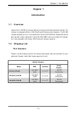
Summary of Contents for SC848 Series

Page 1: ...SC848 CHASSIS SERIES USER S MANUAL 1 0b SUPER SC848A R1K62B SC848E16 R1K62B SC848E26 R1K62B...

Page 2: ...RDWARE SOFTWARE OR DATA STORED OR USED WITH THE PRODUCT INCLUDING THE COSTS OF REPAIRING REPLACING INTEGRATING INSTALLING OR RECOVERING SUCH HARDWARE SOFTWARE OR DATA Any disputes arising between manu...

Page 3: ...It provides information for the installation and use of the SC848 chassis Installation and maintenance should be performed by experienced technicians only This manual lists compatible parts available...

Page 4: ...on the system interface which includes the functions and information provided by the control panel on the chassis as well as other LEDs located throughout the system Chapter 4 Chassis Setup and Maint...

Page 5: ...ifications This chapter lists the specifications of the power supplies provided with your chas sis For additional information refer to the Supermicro website at www supermicro com Appendix C BPN SAS 8...

Page 6: ...Definition 2 1 Installation Instructions 2 4 Circuit Breaker 2 5 Power Disconnection Warning 2 6 Equipment Installation 2 8 Restricted Area 2 9 Battery Handling 2 10 Redundant Power Supplies 2 12 Bac...

Page 7: ...s 4 17 4 8 Power Supply 4 19 4 9 Changing the Power Distributor Board 4 21 4 10 Configuring the Peripheral Drawer 4 24 Removing the Peripheral Drawer 4 25 Installing 2 5 and 3 5 Drives in the Peripher...

Page 8: ...Releasing the Inner Rail 5 5 Installing The Inner Rails on the Chassis 5 6 Installing the Outer Rails on the Rack 5 7 Standard Chassis Installation 5 8 Optional Quick Installation Method 5 9 Appendix...

Page 9: ...d design The chassis is equipped with two 1620 Watt high efficiency power supplies The SC848 chassis supports up to 2 1 redundancy for a total of 3240 Watts High performance fans provide ample optimiz...

Page 10: ...To en sure the highest level of professional service and technical support we strongly recommend purchasing exclusively from our Supermicro Authorized Distributors System Integrators Resellers A list...

Page 11: ...ss Super Micro Computer B V Het Sterrenbeeld 28 5215 ML s Hertogenbosch The Netherlands Tel 31 0 73 6400390 Fax 31 0 73 6416525 Email sales supermicro nl General Information support supermicro nl Tech...

Page 12: ...ust be mailed when service is complete For faster service RMA authorizations may be requested online http www supermicro com support rma Whenever possible repack the chassis in the original Supermicro...

Page 13: ...nt for assistance Only certified technicians should attempt to install or configure components Read this appendix in its entirety before installing or configuring components in the Supermicro chassis...

Page 14: ...s riesgos de la corriente el ctrica y familiar cese con los procedimientos est ndar de prevenci n de accidentes Al final de cada advertencia encontrar el n mero que le ayudar a encontrar el texto trad...

Page 15: ...k letsel kan veroorzaken Voordat u aan enige apparatuur gaat werken dient u zich bewust te zijn van de bij een elektrische installatie betrokken risico s en dient u op de hoogte te zijn van de standaa...

Page 16: ...stems an die Stromquelle die Installationsanweisungen lesen Advertencia Lea las instrucciones de instalaci n antes de conectar el sistema a la red de alimentaci n Attention Avant de brancher le syst m...

Page 17: ...ert ist Stellen Sie sicher dass der Nennwert der Schutzvorrichtung nicht mehr als 250 V 20 A betr gt Advertencia Este equipo utiliza el sistema de protecci n contra cortocircuitos o sobrecorrientes de...

Page 18: ...emsbestandteile anzubringen oder zu entfernen Warning The system must be disconnected from all sources of power and the power cord removed from the power supply module s before accessing the chassis i...

Page 19: ...nentes de sistema Attention Le syst me doit tre d branch de toutes les sources de puissance ainsi que de son cordon d alimentation secteur avant d acc der l int rieur du chassis pour installer ou enle...

Page 20: ...stallieren Ersetzen oder Bedienen dieser Ausr stung sollte nur geschultem qualifiziertem Personal gestattet werden Advertencia Solamente el personal calificado debe instalar reemplazar o utilizar este...

Page 21: ...stallation in Bereichen mit beschr nktem Zutritt vorgesehen Der Zutritt zu derartigen Bereichen ist nur mit einem Spezialwerkzeug Schloss und Schl ssel oder einer sonstigen Sicherheitsvorkehrung m gli...

Page 22: ...alent type recommended by the manufacturer Dispose of used batteries according to the manufacturer s instructions Waarschuwing Dit apparaat is bedoeld voor installatie in gebieden met een beperkte toe...

Page 23: ...ecommand e par le fabricant Jeter les piles usag es conform ment aux instructions du fabricant Advertencia Existe peligro de explosi n si la bater a se reemplaza de manera incorrecta Reemplazar la bat...

Page 24: ...s de alimentaci n Para cortar por completo el suministro de energ a deben desconectarse todas las conexiones Attention Cette unit peut avoir plus d une connexion d alimentation Pour supprimer toute te...

Page 25: ...ero es peligroso Tenga cuidado cuando lo revise Attention Lorsque le syst me est en fonctionnement des tensions lectriques circulent sur le fond de panier Prendre des pr cautions lors de la maintenanc...

Page 26: ...des Warnung Die Installation der Ger te muss den Sicherheitsstandards entsprechen Advertencia La instalacion del equipo debe cumplir con las normas de electricidad locales y nacionales Backplane Waars...

Page 27: ...ional laws and regulations Attention L quipement doit tre install conform ment aux normes lectriques nationales et locales Waarschuwing Bij installatie van de apparatuur moet worden voldaan aan de lok...

Page 28: ...s las leyes y reglamentos nacionales Attention La mise au rebut ou le recyclage de ce produit sont g n ralement soumis des lois et ou directives de respect de l environnement Renseignez vous aupr s de...

Page 29: ...dedos los destornilladores y todos los objetos lejos de las aberturas del ventilador Attention Il est possible que les ventilateurs soient toujours en rotation lorsque vous retirerez le bloc ventilat...

Page 30: ...zu einer Fehlfunktion oder ein Brand entstehen Elektrische Ger te und Material Safety Law verbietet die Verwendung von UL oder CSA zertifizierte Kabel UL oder CSA auf der Code f r alle anderen elektri...

Page 31: ...utres appareils lectriques que les produits d sign s par Supermicro seulement AC AC UL CSA UL CSA UL CSA Supermicro UL CSA AC Electrical Appliance and Material Safety Law UL CSA UL CSA Waarschuwing Bi...

Page 32: ...2 20 SC848 Chassis Notes...

Page 33: ...ep you constantly informed of the overall status of the system as well as the activity and health of specific components Most SC848 models have two buttons on the chassis control panel a reset button...

Page 34: ...removes the main power but keeps standby power supplied to the system Therefore it is critical that you unplug the power cord prior to servicing 3 2 Control Panel Buttons There are two push buttons lo...

Page 35: ...ED indicates when illuminated and any corrective action you may need to take Power Indicates that full power is being supplied to the system by power supply units from standby power status This LED sh...

Page 36: ...t condition has occured This may be caused by cable congestion Blinking red 1Hz Fan failure check for an inoperative fan Blinking red 0 25Hz Power failure check for a non operational power supply Soli...

Page 37: ...solid on state this blue LED on the front of the SAS SATA drive carrier indicates that the drive is present A connection to the SAS SATA backplane enables this LED to blink on and off when that parti...

Page 38: ...SC848 Chassis Manual 3 6 Notes...

Page 39: ...ing up your chassis Review the warnings and precautions listed in the manual before setting up or servicing this chassis These include information in Chapter 2 Standardized Warning Statements for AC S...

Page 40: ...e present 3 Simultaneously press the release tabs to free the top cover from the locked position 4 Slide the top cover toward the rear of the chassis 5 Lift the top cover off the chassis Warning Excep...

Page 41: ...ive carriers which may be removed from the chassis without powering down the server Removing Hard Drive Carriers from the Chassis 1 Press the release button on the drive carrier This extends the drive...

Page 42: ...Installing a Hard Drive to the Hard Drive Carrier 1 Remove the two screws securing the dummy drive to the drive carrier and remove the dummy drive Place the hard drive carrier on a flat surface such a...

Page 43: ...es in both the drive carrier and the hard drive 4 Secure the hard drive to the carrier using six screws 5 Install the drive carrier back into the chassis Make sure to close the drive carrier handle to...

Page 44: ...move the cords from the back of the power sup plies and remove the chassis top cover as described in Section 4 2 2 With the illustrations facing the outside of the chassis place the shield into the sp...

Page 45: ...ard if necessary and lift the middle fan bracket up and out of the chassis Figure 4 8 Chassis Standoffs Figure 4 9 Removing the Middle Fan Bracket Permanent and Optional Standoffs Standoffs prevent sh...

Page 46: ...sis and tighten the standoff with a wrench 5 Lay the motherboard on the chassis aligning the permanent and optional standoffs 6 Secure the motherboard to the chassis using the rounded Phillips head 6...

Page 47: ...g the guide brackets to the chassis walls and set them aside Reattach the guide brackets in the optional fan bracket position using the screws previously set aside 10 Carefully slide the middle fan br...

Page 48: ...heatsinks may vary with different motherboards Typically heatsinks will be secured to the motherboard with screws and may be installed without remov ing the motherboard After powering down the system...

Page 49: ...chassis top cover 2 Remove the screw holding the cover in place for each expansion card slot you want to use Keep this screw for later use 3 Simultaneously insert the expansion card into the PCI slot...

Page 50: ...marked 32 DIMM and the left outer side piece 32 DIMM Remove all pieces marked 16 DIMM and the left inner side piece Air Shroud Part No Description MCP 310 84802 0B Mylar air shroud for AMD H8Q mother...

Page 51: ...ards Remove the two posts X9QR7 TF Motherboard Keep the two posts X8QB6 F and X8QB6 LF Motherboards Installing the Air Shroud 1 Power down the system remove the cords from the back of the power sup pl...

Page 52: ...SC848 Chassis Manual 4 14 X9QR7 TF JBOD X9QR7 TF X8Q Series H8Q Series Figure 4 16 Air Shrouds for Various Motherboards...

Page 53: ...ecommended server parts 3 Make sure no wires or foreign objects obstruct air flow through the chassis Pull all excess cabling out of the airflow path or use shorter cables The control panel LEDs infor...

Page 54: ...n 2 Power down the system unplug the cords from the back of the power sup plies and remove the chassis top cover 3 Press the fan release tab to lift the failed fan from the chassis and pull it complet...

Page 55: ...al System Fan 1 Power down the system unplug the cords from the back of the power sup plies and remove the chassis cover 2 If you are installing an external fan for the first time locate the external...

Page 56: ...e 1 3 5 Bring the external fan cage to an upright position against the rear of the chas sis and secure it with two screws as illustrated Open the breakable cover next to the fan and pass the fan conne...

Page 57: ...e SC848 chassis includes 1 1 redundant up to 2 1 redundant power supply modules Any one of the three power supply modules may be removed and new units added without having to power down the server The...

Page 58: ...SC848 Chassis Manual 4 20 3 Push the new power supply module or dummy cover into the power bay until it clicks into the locked position Figure 4 26 Installing the Power Supply 1 3...

Page 59: ...distributor board cables from the motherboard backplane and other components and remove all power supplies 4 Locate the power distributor board bracket underneath the chassis floor between the power...

Page 60: ...e front of the power distributor board bracket as described in figure 4 28 Plug the 24 pin and 8 pin motherboard connector cables to the HDD backplane from the side of the power distributor board brac...

Page 61: ...the motherboard evenly before replacing the middle bracket Make sure the wires passing through the gates of the bracket are not being squeezed 13 Return the power supplies to their bays in the chassi...

Page 62: ...Dual 2 5 HDD MCP 220 00044 0N 3 Dummy Cover MCP 290 11101 0B 4 Slim USB MCP 220 00065 0B 5 Slim 2 5 HDD MCP 220 00066 0B 6 Slim FDD MCP 220 00067 0B 7 Slim DVD MCP 220 00068 0N Location Peripheral De...

Page 63: ...riph eral drawer to other system components Including the motherboard and the power distributor board 4 Reach beneath the underside of the chassis floor Pull the peripheral drawer release button while...

Page 64: ...p to two 3 5 HDDs four 2 5 HDDs or a combination of one 3 5 and two 2 5 HDDs in the peripheral drawer Installing HDDs into the Peripheral Drawer 1 Secure the drive into the peripheral drawer using one...

Page 65: ...eral Drawer Installing Peripheral Devices in the Peripheral Drawer Installing Peripheral Devices 1 Remove the dummy covers from the front of the peripheral device bays on the front of the peripheral d...

Page 66: ...ving Peripheral Devices 1 Press the release latch on the back of the peripheral device bay towards the wall of the drawer Figure 4 38 Peripheral Device Release Latches Figure 4 39 Removing Peripheral...

Page 67: ...ted in the diagram below 4 Push the drawer back into the chassis while simultaneously pulling the cables which lead to the drawer without breaking or disconnecting the cables until the drawer clicks i...

Page 68: ...the power cords from the back of the power supply and remove the chassis cover 2 Pull all of the existing hot swappable hard drives half way out of their drive bays in the front of the chassis 3 Disco...

Page 69: ...use Remove Five Lower Screws Remove Six Screws Along the Middle of the Backplane Remove Five Screws Along the Bottom of the Backplane 7 Gently ease the backplane and backplane housing up and out of th...

Page 70: ...en screws previ ously used 2 Gently slide the backplane with its housing back into position in the chassis 3 Replace the five lower screws which secure the backplane housing to the chassis base 4 Repl...

Page 71: ...which secure the backplane housing to the chassis 6 Reconnect all cables to the backplane 7 Plug the power cords into the rear of the power supplies replace the chassis cover and power up the system...

Page 72: ...SC848 Chassis Manual 4 34 Notes...

Page 73: ...nerated The system needs to be placed near a grounded power outlet Be sure to read the Rack and Server Precautions in the next section 5 3 Preparing for Setup The box your chassis was shipped in shoul...

Page 74: ...he rack to become unstable General Server Precautions Review the electrical and general safety precautions that came with the com ponents you are adding to your chassis Determine the placement of each...

Page 75: ...possible overloading of circuits might have on overcurrent protection and power supply wiring Appropriate consideration of equipment nameplate ratings should be used when addressing this concern Relia...

Page 76: ...ck between 26 5 and 36 4 deep Identifying the Sections of the Rack Rails The chassis package includes two rail assemblies in the rack mounting kit Each assembly consists of three sections An inner cha...

Page 77: ...the rack This prevents the server from coming completely out of the rack when when the chassis is pulled out for servicing Releasing the Inner Rail Releasing Inner Rail from the Outer Rails 1 Identify...

Page 78: ...of the chassis aligning the hooks on the side of the chassis with the holes in the inner rail 3 Slide the inner rail forward toward the front of the chassis until the rail clicks into the locked posi...

Page 79: ...essary use screws to secure the outer rails to the rack as illustrated above 4 Pull out the rear of the outer rail adjusting the length until it fits within the posts of the rack 5 Hang the hooks of t...

Page 80: ...le rails keeping the pressure even on both sides until the locking tab of the inner rail clicks into the front of the middle rail locking the chassis into the fully extended position 6 Depress the loc...

Page 81: ...is onto a rack Installing the Chassis into a Rack 1 Install the whole rail assembly onto the rack as described on page X 7 2 Release the inner rail without retracting the middle rail 3 Install the inn...

Page 82: ...SC848 Chassis Manual 5 10 Notes...

Page 83: ...eb site at www supermicro com A 2 Cables Included with SC848 Chassis SAS SATA SC848A R1K62B SC848E16 R1K62B SC848E26 R1K62B Part Type Length Description CBL 0174L Cable 6 US power cord 14 AWG CBL 0071...

Page 84: ...ers Number of Pins Cable Part Length 24 pin CBL 0042 7 9 20 cm 20 pin CBL 0059 7 9 20 cm 8 pin CBL 0062 7 9 20 cm 4 pin CBL 0060 7 9 20 cm Front Panel to the Motherboard The SC836 chassis includes a c...

Page 85: ...m 0 157 RAIL Round head M4 x 4 mm 0 157 Flat head M5 x 12 mm 0 472 Washer for M5 DVD ROM CD ROM and FLOPPY DRIVE Flat head 6 32 x 5 mm 0 197 Pan head 6 32 x 5 mm 0 197 Round head M3 x 5 mm 0 197 Pan h...

Page 86: ...SC848 Chassis Manual A 4 Notes...

Page 87: ...62B SC848E26 R1K62B 1620W up to 2 1 for a total of 4860W MFR Part PWS 1K62P 1R AC Input 1000W Output 100 120V 12 10A 50 60Hz 1200W Output 120 140V 12 10A 50 60Hz 1620W Output 180 240V 10 5 8A 50 60Hz...

Page 88: ...SC848 Chassis Manual B 2 Notes...

Page 89: ...prevent static discharge Touch a grounded metal object before removing a component from the antistatic bag Handle the RAID card by its edges only do not touch its components peripheral chips memory m...

Page 90: ...wn in this manual C 4 Introduction to the SAS 846A Backplane The SAS 846A backplane has been designed to utilize the most up to date technol ogy available providing your system with reliable high qual...

Page 91: ...ESET 2 3 NO RESET 1 2 RESET 2 3 NO RESET 1 2 RESET 22 23 20 21 18 19 16 17 14 15 12 13 10 11 8 9 6 7 4 5 3 2 1 0 JP129 9072 3 RESET JP35 9072 1 RESET JP50 9072 2 RESET BUZZER RESET 2 3 NO FAN 1 2 WITH...

Page 92: ...the front panel For the Activity LED Header to work properly connect using a 10 pin LED cable 4 5 6 I2 C Connectors The I2 C Connectors designated JP37 JP95 JP52 JP96 JP116 and JP117 are used to moni...

Page 93: ...C D89 A C C85 C84 C5 C45 C44 C3 C204 C203 C202 C201 C200 C199 C198 C197 C119 C285 C330 C329 C328 C327 C326 C325 C324 C323 C283 C229 C20 C193 C19 C173 C318 1 16 49 64 U73 U40 U19 I2C 2 CH 20 23 CH 12...

Page 94: ...s 2 3 No Fan FAN 2 JP63 Pins 1 2 With Fan Default Pins 2 3 No Fan FAN 3 JP99 Pins 1 2 With Fan Default Pins 2 3 No Fan FAN 3 JP64 Pins 1 2 With Fan Default Pins 2 3 No Fan FAN 4 JP100 Pins 1 2 With Fa...

Page 95: ...P25 JP100 JP18 F4 D54 A C D53 A C D36 A C D3 A C D51 A C D49 A C D47 A C D45 A C D89 A C C85 C84 C5 C45 C44 C3 C204 C203 C202 C201 C200 C199 C198 C197 C119 C285 C330 C329 C328 C327 C326 C325 C324 C323...

Page 96: ...IL 16 21 20 19 18 12 13 14 15 9 8 7 6 3 2 1 0 SAS SAS SAS SAS SAS SAS SAS SAS SAS SAS SAS SAS SAS SAS SAS SAS FAIL 12 ACT 12 ACT 8 FAIL 8 ACT 4 FAIL 4 ACT 0 FAIL 0 C 8 Rear Connectors and LED Indicato...

Page 97: ...SAS 2 D14 D7 SAS 3 D15 D8 SAS 4 D18 D19 SAS 5 D21 D20 SAS 6 D22 D23 SAS 7 D24 D29 SAS 8 D25 D30 SAS 9 D26 D31 SAS 10 D27 D32 SAS 11 D28 D33 SAS 12 D40 D37 SAS 13 D41 D38 SAS 14 D42 D39 SAS 15 D87 D88...

Page 98: ...C 10 SC848 Chassis Manual Notes...

Page 99: ...to prevent static discharge Touch a grounded metal object before removing a component from the antistatic bag Handle the backplane by its edges only do not touch its components peripheral chips memory...

Page 100: ...shown in this manual D 4 Introduction to the SAS 846EL Backplane The SAS 846EL backplane has been designed to utilize the most up to date technol ogy available providing your system with reliable hig...

Page 101: ...ATFAIL1 FANFAIL1 BUZZER_ENB1 REMOTE_FAN_FAIL_SOCKET1 PWR6 PWR4 PWR5 PWR3 PWR2 PWR1 BAR CODE 2 A C A C A C A C 5V 12V GND GND 5V 12V GND GND 5V 12V GND GND 5V 12V GND GND 5V 12V GND GND 5V 12V GND GND...

Page 102: ...itions Backplane Main Power 4 Pin Connector Pin Definition 1 12V 2 and 3 Ground 4 5V 3 Backplane Main Power Connectors The 4 pin connectors designated PWR1 PWR2 PWR3 PWR4 PWR5 and PWR6 provide power t...

Page 103: ...N3 provide power to the fans See the table on the right for pin definitions Fan Connectors Pin Definition 1 Ground 2 12V 3 Tachometer 8 13 SAS Ports The primary and secondary sets of SAS ports provide...

Page 104: ...BUZZER1 5V_LED1 OVERHEATFAIL1 FANFAIL1 BUZZER_ENB1 REMOTE_FAN_FAIL_SOCKET1 PWR6 PWR4 PWR5 PWR3 PWR2 PWR1 BAR CODE 2 A C A C A C A C 5V 12V GND GND 5V 12V GND GND 5V 12V GND GND 5V 12V GND GND 5V 12V...

Page 105: ...SEC_MODE1 Pins 1 2 Factory Setting Do not change BUZZER_ENB1 Open Disable Closed Enable Buzzer Enable Front Panel LEDs LED State Specification OVERHEATFAIL1 On Overheat Drive Failure LED Indicator Red...

Page 106: ...5 D 3 6 D 3 7 D 6 8 D 3 2 D 3 1 D 3 0 D 2 9 D 2 8 D 2 7 D 2 6 A C T 1 6 A C T 1 7 A C T 1 8 A C T 1 9 A C T 2 0 A C T 2 1 A C T 2 2 A C T 2 3 F A I L 1 8 F A I L 1 9 F A I L 2 0 F A I L 2 1 F A I L 2...

Page 107: ...4 FAIL 4 SAS 5 ACT 5 FAIL 5 SAS 6 ACT 6 FAIL 6 SAS 7 ACT 7 FAIL 7 SAS 8 ACT 8 FAIL 8 SAS 9 ACT 9 FAIL 9 SAS 10 ACT 10 FAIL 10 SAS 11 ACT 11 FAIL 11 SAS 12 ACT 12 FAIL 12 SAS 13 ACT 13 FAIL 13 SAS 14 A...

Page 108: ...ngle Ports SAS 846EL1 backplanes have a single port expander that access all twenty four drives and supports cascading Dual Ports SAS 846EL2 backplanes have dual port expanders that access all twenty...

Page 109: ...17 WWN SAS HBA Port A Expander 1 Port B Expander 2 Figure D 6 Single HBA The SAS 846EL2 backplane has two expanders which allow effective failover D 10 Failover PRI_J0 PRI_J1 PRI_J2 SEC_J0 SEC_J1 SEC_...

Page 110: ...tion to all drives Figure D 9 Dual HBA Failover D 11 Failover with RAID Cards and Multiple HBAs The SAS 836EL backplane may be configured for failover with multiple HBAs using either RAID controllers...

Page 111: ...figuration the first chassis includes a motherboard and at least one Host Bus Adapter HBA Other servers in this enclosed system include a power card This section describes the supported power card for...

Page 112: ...tween the internal HBA and SAS 846EL backplane The cables required depend on the HBA connector HBA Host Bus Adapter PRI_J0 PRI_J1 PRI_J2 SEC_J0 SEC_J1 SEC_J2 J17 WWN Connecting an Internal Host Bus Ad...

Page 113: ...has an iPass SFF 8087 mini sas connector 36 pins at each end It connects from the HBA to the SAS 846EL backplane Cable Name iPass mini SAS to iPass mini SAS Part CBL 0108L 02 Length 39 cm 15 inches Pa...

Page 114: ...dapter Power Card HBA Host Bus Adapter Dual External Host Bus Adapter CBL 0200L External HBA Cables HBA Host Bus Adapter Power Card CBL 0200L External HBA Cable PRI_J0 PRI_J1 PRI_J2 SEC_J0 SEC_J1 SEC_...

Page 115: ...ollowing cable if your external HBA has an InfiniBand connector Description This cable has an InfiniBand connector SFF 8470 on one end and an SFF 8088 1X 26 pins at the other end Cable Name SAS Infini...

Page 116: ...B Expander 2 Power Card PRI_J0 PRI_J1 PRI_J2 SEC_J0 SEC_J1 SEC_J2 J17 WWN Port B Expander 2 Port A Expander 1 Connecting Multiple Backplanes in a Single Channel Environment This section describes the...

Page 117: ...088 1x to SFF 8088 x1 Ports Single or Dual Placement External cable Description Internal cable Connects the backplane to the Host Bus Adapter HBA or external port Used in single port environments Cabl...

Page 118: ...r 1 Port B Expander 2 Cable 0168L with Single Port Assembly internal cable Connecting Multiple Backplanes in a Dual Channel Environment This section describes the cables used when cascading from dual...

Page 119: ...ual Placement Internal cable Description External cascading cable Connects ports between servers Use one cable for single port connections and two cables for dual port connections Cable Name SAS EL2 E...

Page 120: ...see the SC846 Chassis Manual available at www supermicro com D 13 Supported Cascading Configurations Cable 0167L internal cable Cable 0166L external cable Single Port Cable Assembly HBA Host Bus Adap...

Page 121: ...xpander 1 Power Card PRI_J0 PRI_J1 PRI_J2 SEC_J0 SEC_J1 SEC_J2 J17 WWN Port A Expander 1 Power Card PRI_J0 PRI_J1 PRI_J2 SEC_J0 SEC_J1 SEC_J2 J17 WWN Port A Expander 1 Power Card PRI_J0 PRI_J1 PRI_J2...

Page 122: ...xpander 1 Power Card PRI_J0 PRI_J1 PRI_J2 SEC_J0 SEC_J1 SEC_J2 J17 WWN Port A Expander 1 Cable 0168L internal cable Dual Port Cable Assembly Figure D 24 Dual SAS HBA with Cascaded Configuration Dual S...

Page 123: ...er Card Port B Ex 2 Port A Ex 1 Port A Ex 1 Power Card Port B Ex 2 Port A Ex 1 Power Card Port B Ex 2 Port A Ex 1 Figure D 25 Dual SAS HBA with Cascaded Configuration and Branching Dual SAS HBA and Ca...

Page 124: ...reasonably expected to result in significant injury or loss of life or catastrophic property damage Accordingly Supermicro disclaims any and all liability and should buyer use or sell such products fo...

Reviews: