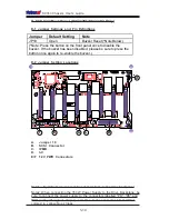
background image

1.1b

SC743 CHASSIS

USER'S  GUIDE

Summary of Contents for Supero SC743

Page 1: ...1 1b SC743 CHASSIS USER S GUIDE...

Page 2: ...Y TO USE THIS PRODUCT OR DOCUMENTATION EVEN IF ADVISED OF THE POSSIBILITY OF SUCH DAMAGE IN PARTICULAR THE VENDOR SHALL NOT HAVE LIABILITY FOR ANY HARDWARE SOFTWARE OR DATA STORED OR USED WITH THE PRO...

Page 3: ...ents of the Accessory Kit 2 1 B Chassis Front View and the Front Control Panel 2 2 C Chassis Rear View and the Back Panel 2 4 2 2 Chassis Installation 2 6 A Important Safety Guidelines 2 6 B Tools Nee...

Page 4: ...C13 type female connector zBe sure to disconnect the power supply before accessing the SC743 or its components zPlug the Power cord s into a socket that is properly grounded before turning on the pow...

Page 5: ...o the manufacturer s instructions CD ROM Laser CAUTION Do not open the enclosures of power supplies or CD ROM to avoid injury 1 2 General Safety Guidelines Warning Follow the guidelines below to avoid...

Page 6: ...odules avoid touching their pins Put the motherboard and peripherals back into their antistatic bags when not in use For grounding purposes make sure your computer chassis provides excel lent conducti...

Page 7: ...and fasteners to remove the cover or components 2 Save all the screws and fasteners for later use If necessary label these screws or fasteners for easy identification 3 Follow the instruction given i...

Page 8: ...rack assembly must provide sufficient airflow to the chassis for proper cooling 1 5 Product Compliance Information The SC743 Chassis is compliant with the following safety standards requirements Prod...

Page 9: ...SE PT17 B IDE Drive Carriage SC743i only 2 CSE PT31 B 80mm Hot Swap Chassis Fan 4 FAN 0072 80mm Rear Chassis Fan Hot Swap 2 Fan 0073 650W Power Supply 1 PWS 0056 8 port SCSI Single channel w SAF TE Ba...

Page 10: ...A 743S1 Fan Shroud Rev B 1 CSE PT54 SCSI Cable 9 SC743S1 only 1 CBL 033 U320 Component Quantity Part Number SCA 1 Drive Tray SC743S1 only 8 CSE PT17 B IDE Drive Carriage SC743i only 2 CSE PT31 B 80mm...

Page 11: ...3 Fan Shroud 1 CSE PT54 Component Qty Part Number SCA 1 Drive Trays 8 CSEPT17 B 80mm Hot Swap Chassis Fan 4 FAN 0072 80mm Hot Swap Rear Chassis Fan 2 FAN 0073 650W Power Supply 1 PWS 0056 8 port SATA...

Page 12: ...ty Part Number SCA 1 Drive Trays 8 CSEPT17 B 80mm Hot Swap Chassis Fan 4 FAN 0074 645W Power Supply 1 PWS 0060 8 port SATA Backplane 1 CSE SATA 743 Fan Shroud Rev B 1 CSE PT54 1 7B Packing List Chassi...

Page 13: ...nput frequency 50 60 Hz Rated input current 14A 115V 8A 230V Rated output power 760W Maximum rated BTU 4350 BUTs Hr Nominal DC output 3 3V 36A 5V 36A 12V 50A combined 12V 1A 5V Standby 3 5A Note When...

Page 14: ...er Setting Locations A B C D E F Note1 By default we connect four chassis fans to the drive backpanel Note2 When connecting the 760W Power Supply to the Drive Backplane be sure to connect the power su...

Page 15: ...ermicro Setup CD is in 8 Choose Qlogic folder and click on Open 9 System will automatically detect GEM318 and install the drive from this point on or 1 Right click the My Computer icon on your desktop...

Page 16: ...Pin Power Connectors Refer to Table 1 on the right for pin definitions B JP26 HDD Activity Refer to Table 2 on the right for pin definitions C JP25 Overheat Temperatures Refer to Table 3 on the right...

Page 17: ...4 Jumpers Headers Locations A1 A2 C D E D25 D26 D22 D23 D21 D20 D18 D19 B A Pin1 Pin2 Pin3 Pin4 Pin1 Pin2 Pin3 Pin4 Pin5 A1 A2 JP10 JP13 PWR Connectors B JP26 HDD ACT Pin6 Pin7 Pin8 Pin9 Pin10 D15 D8...

Page 18: ...1 18 SC743 Chassis User s Guide Notes...

Page 19: ...hassis Description and Installation Procedures G H F F Flat head M4 x 4 mm 0 157 RAIL I G Round head M4 x 4 mm 0 157 H Flat head M5 x 12 mm 0 472 I Washer for M5 B B Flat head 6 32 x 5 mm 0 197 DRIVE...

Page 20: ...on Definitions A Power Button Chassis Front Panel Front Panel I O Device Definitions K B System Reset C Power Indicator D HDD Activity Indicator E F LAN Indicators H Power Failure Indicator K Hot Swap...

Page 21: ...tion Green On System On Power Off System Off Green Blink HDD Activity HDD Activity Off No Activity Green On Linked Blink LAN Activity LAN Indicators Off Disconnected Red On System Overheat Overheat Fa...

Page 22: ...C Chassis Rear View and the Back Panel SC743 Chassis Rev A Rear View Back Panel Devices A Power Supply Module B Back Panel I O Ports C Rear System Fans A B C D D Full size PCI Expansion Slots SC743 C...

Page 23: ...eo Ports H LAN1 LAN2 K Parallel Port Power Module LED Descriptions Note The actual I O Configuration of your system might be different from the one shown above E F G H I Color Condition Description Gr...

Page 24: ...e power supply connected to the SC743 2 Unplug all power cords from the system or the wall outlets 3 Disconnect all the cables and label the cables for easy identification 4 Use a grounded wrist strap...

Page 25: ...assis Procedures 1 Unlock and open the drive tray door as shown below 2 Press the release tab located on the drive tray door to release the drive tray from its locking position 3 Pull the drive tray d...

Page 26: ...ling any components replacing chassis fans or accessing the motherboard you will first need to remove the side cover Procedures 1 Press the release tab to unlock the side cover 2 Once the release tab...

Page 27: ...ssing the release tab pull the fan module from the chassis Note When installing the fan module into the chassis be sure to push the fan module into the fan module slot until you hear the click The cli...

Page 28: ...ick 2 Press the release tab on the back side of the rear chassis fan to loosen it as shown above 3 Once the release tab is loosened pull the air shroud from the chassis Note When installing the air sh...

Page 29: ...n below Push the release tab down to unlock the rear chassis fan 2 Once the rear chassis fan is unlocked you can remove the fan from the chassis as shown above Note When installing the fan module into...

Page 30: ...right to release the power supply from its locking position as shown below 3 Once the power supply module is released from its locking position remove it from the chassis Warning Do not open the casin...

Page 31: ...he motherboard before installing the motherboard into the chassis Refer to Chapter 1 for Safety Guidelines Procedures Note the motherboard shown above is for reference only The mother board is not inc...

Page 32: ...g For proper cooling please make sure that the air shroud and all the chassis covers are installed before you operate the system Out of warranty damage can occur if this rule is not strictly followed...

Page 33: ...or cables into this area Procedures 1 Remove the two screws as shown in the picture below 2 Remove the three screws on the bottom of the bracket between the Back Panel and the Mid plane 3 Use a screw...

Page 34: ...ing PCI cards please follow the instructions below to access the PCI slot brackets 3 Once the PCI slot bracket is unlocked pull the release tab upward and remove the PCI slot bracket from the chassis...

Page 35: ...also accommodate up to five 3 5 devices To configure the module for the use of 3 5 devices you need to rotate the module 90 degrees as shown on the next page 3 You can also simply rotate the storage m...

Page 36: ...ver to unlock it Once it is unlocked push the top cover out of the chassis 2 Remove the screw from each chassis foot 3 Use a flat head screw driver to gently pry the chassis foot out of the chassis Pr...

Page 37: ...Instructions 4 5 4 Locate the release tab on top of the storage module as shown below Press the release tab to unlock the storage module 5 Once the storage module is unlocked push the module out of th...

Page 38: ...he storage module to support 3 5 devices or Mobile Racks 3 Remove the storage module from its housing and then remove the screws and module brackets from the storage module 4 Install 3 5 devices into...

Page 39: ...hroud with the guide rails and gently push the air shroud into the chassis until both rear release tab and the front release tab are seated properly and you hear the click Warning For proper cooling p...

Page 40: ...lug the AC power cord s 3 Remove all external devices and connectors 2 Install the inner rails onto the chassis by tightening the screws provided Make sure that the rails are flush against the edge of...

Page 41: ...another set of outer rail assembly onto another side of the racks 4 Insert the inner rails which are attached to the SC743 chassis into the openings of the outer rail assemblies and gently push the ch...

Page 42: ...2 24 SC743 Chassis User s Guide Notes...

Page 43: ...Mobile Rack Installing the CSE M34S CSE M34T Addendum A...

Page 44: ...sis User s Guide A 2 Table of Contents 1 Packaging List 3 2 Technical Specifications 3 3 Jumper Settings 4 4 Hardware Installation Procedures 6 5 SCSI Super GEM Drive Installation Instructions for Win...

Page 45: ...counts of 6 32 hex washer head screws Eight 8 counts of M3 washer head screws Eighteen 18 counts of Pan head screws Drive Carrier Four 4 CSE PT10 beige only For the CSE M34T only Serial ATA Backplane...

Page 46: ...mper Description Setting JP14 Delay Start Closed Enable Open Disable Default JP18 Buzzer Reset Closed Enable Open Disable Default JP25 Overheat Temperature Open 50o C 1 2 55o C Default 2 3 60o C JP21...

Page 47: ...JP25 Overheat Temperature Open 45O C 1 2 50O C Default 2 3 55O C JP28 Fan Sense 1 2 Enabled if a fan is not present the alarm will sound Default 2 3 Disabled JP26 Common Act 1 Act 4 Connect this heade...

Page 48: ...s See the previous section for SCSI ID jumper settings 2 SCSI termination is enabled by default on the SCSI backplane 3 To install the CSE M34 Mobile Rack into the SC743 chassis please refer to Chapte...

Page 49: ...hown below Remove the screws Access the backplane 2 Pull out the rear fan bracket as shown below The CSE M34T SATA Model The CSE M34S SCSI Model Pull out the rear fan bracket B Accessing the Drive Bac...

Page 50: ...item Specify a location and choose Next 7 Click on Browse and choose D drive or wherever Supermicro Setup CD is in 8 Choose Qlogic folder and click on Open 9 System will automatically detect GEM318 a...

Page 51: ...Mobile Rack Installing the CSE M35S CSE M35T1 Addendum B...

Page 52: ...SC743 Chassis User s Guide B 2 Table of Contents 1 Packaging List 3 2 Technical Specifications 4 3 Jumper Settings 5 4 Installation Procedures 7...

Page 53: ...320 160 Hard drives which provide configuration flexibility and maximum data integrity 1 Packing List Please check to see if you have received all the items listed below CSE M35S CSE M35T1 Mobile Rac...

Page 54: ...eceptacle Connectors SATA hot swap hard drives CSE M35T 1 only Cooling Subsystem One 1 9cm Exhaust Fan System Monitoring Fan Fail Detection LED and Alarm Overheat LED indication Drive Fail Alarm and I...

Page 55: ...t Closed Enable Open Disable Default JP21 SCSI Termination Closed Enable Default Open Disable JP24 SCSI ID Selection 1 2 SCSI Ids 0 1 2 3 4 Default 2 3 SCSI Ids 9 10 11 12 13 JP29 GEM 318 IDs 1 2 ID6...

Page 56: ...ivity LEDs Pin Definitions Act LED 1 Act LED 2 Act LED 3 Act LED 4 Act LED 5 Channel 1 Channel 2 Channel 3 Channel 4 Channel 5 Jumper Description Setting JP18 Buzzer Reset Closed Enable Open Disable D...

Page 57: ...te For the CSE M35S 1 SCSI IDs are assigned automatically by the backplane Do not set IDs manually on the drives See the previous section for SCSI ID jumper settings 2 SCSI termination is enabled by d...

Page 58: ...SC743 Chassis User s Guide B 8 3 Mount a drive in a carrier as shown below 2 Swing the handle outward and pull out the unit as shown below...

Page 59: ...on both sides of the unit as shown be low 2 Pull out the fan as shown below Note For the SC 743 Chassis the CSE M35 Rear Exhaust Fan should not be used Instead the hot swap 120mm Chassis Fans include...

Page 60: ...Chassis User s Guide B 10 C Accessing the Drive Backplane 1 Unscrew the screw located on the side of the unit as shown below 2 Pull out the Rear Bracket as shown below 3 Access the Backplane as shown...

Reviews: