
MODELS:
_________
MS-65
MS-90
MS-150
MS-225
MS-300
MS-400
IMPORTANT NOTE
:
As you follow these instructions, you will notice warning and caution symbols. This blocked information is important for the
safe and efficient installation and operation of this generator.
These are two types of potential hazards that may occur during this installation and operation:
!
WARNING
!
CAUTION
Table of Contents: . . . . . .
Page
Before Installing . . . . . . . . . . . . . . . . . . . . . 1
Steam Room Requirements . . . . . . . . . . . . 1
Locating the Steam Generator Unit . . . . . . 2
Typical Installation . . . . . . . . . . . . . . . . . . . 2
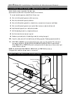
MS Super 4, 5, 6 Typical Installation. . . . . . 3
Installation . . . . . . . . . . . . . . . . . . . . . . . . . 4
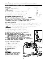
Plumbing
Water Supply
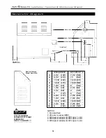
Generator Dimensions . . . . . . . . . . . . . . . . 5
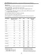
Electrical Specifications . . . . . . . . . . . . . . . 6
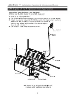
Input Power Wiring . . . . . . . . . . . . . . . . . . 7
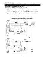
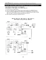
Wiring Diagrams . . . . . . . . . . . . . . . . . . 8- 10
Optional Autoflush Feature . . . . . . . . . . . 11
Check Out & Operation . . . . . . . . . . . . . . 12
Major Electrical Systems Test . . . . . . . . . . 12
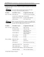
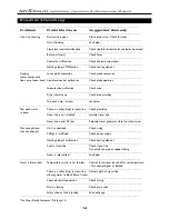
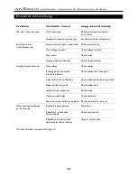
Trouble Shooting . . . . . . . . . . . . . . . . 13- 15
Five Easy Steps to Properly Size . . . . . . . . 16
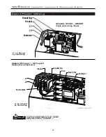
Replacement Parts Diagram . . . . . . . . . . . 17
Replacement Parts List . . . . . . . . . . . . . . . 18
Warranty . . . . . . . . . . . . . . . . . . . . . . . . . 19
states a hazard may cause serious
injury or death if precautions are
not followed.
signals a situation where minor
injury or product damage may occur
if you do not follow instructions.
IMPORTANT NOTE
:
This highlights information that is especially
relevant to a problem-free installation.
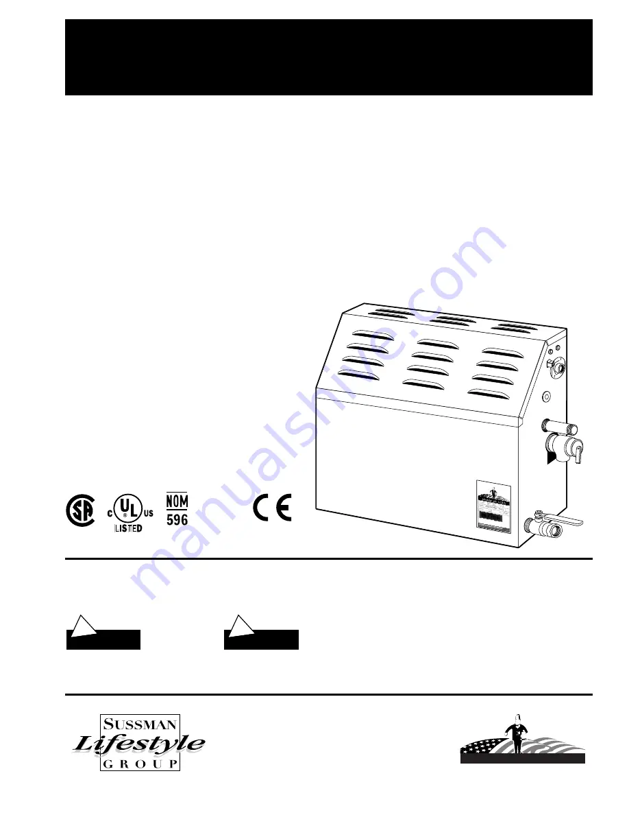
MrSteam
PUR 101289 Rev. 4/01
MrSteam
®
Residential Steambath Generator Systems
Installation,Operation & Maintenance Manual
A Division of Sussman-Automatic Corporation
43-20 34th Street, Long Island City, NY 11101 • (718) 937-4500
1-800-767- 8326 • Fax: (718) 472-3256 • www.mrsteam.com
Western Regional Offices
9410 S. La Cienega Blvd., Inglewood CA 90301
1-800 72 STEAM (1-800 727-8326) • Fax: (310) 216-2944
Steam Outlet
Steam Head
Made in USA
Listed Steam Bath
Generator 777D
ANSI
Drain
Safety Valve
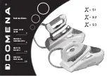
MS-SUPER 1
MS-SUPER 2
MS-SUPER 3
MS-Super 4
MS-Super 5
MS-Super 6
MODEL____________ Serial No._________________