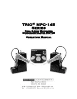
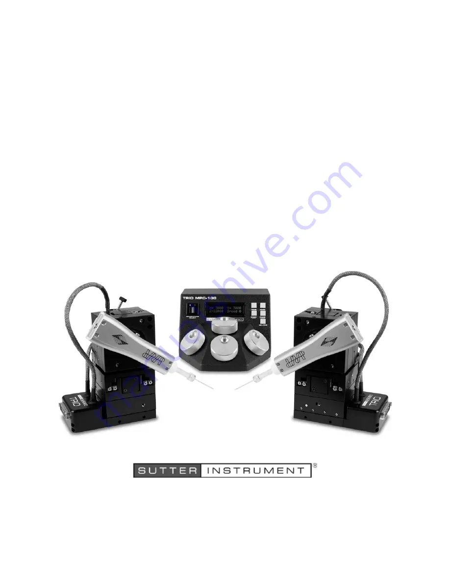
background image


One Digital Drive 

Novato, CA 94949 


Voice:  415-883-0128  Web:  www.sutter.com 

Fax: 

415-883-0572  Email: info@sutter.com 


TRIO

 MPC-145 

Series 


Dual 3-Axis Motorized 

Micromanipulator System 

With Synthetic Fourth Diagonal Axis  


Operation Manual 

Rev. 2.62c (20191001) (FW v2.62) 

Summary of Contents for TRIO MP-845 Series

Page 1: ...4949 Voice 415 883 0128 Web www sutter com Fax 415 883 0572 Email info sutter com TRIO MPC 145 Series Dual 3 Axis Motorized Micromanipulator System With Synthetic Fourth Diagonal Axis Operation Manual...

Page 2: ...00 ROE controller and two TRIO MP 845M micromanipulators one right handed and the other left handed The Sutter Instrument dPatch Headstage shown mounted on each micromanipulator are not included in th...

Page 3: ......

Page 4: ......

Page 5: ...electrical noise and mechanical vibration Surge suppression is always recommended NOTE There are no user replaceable fuses in the TRIO MPC 100 system The TRIO MPC 100 system s power supply consists of...

Page 6: ...result in damage to the motors Never touch any part of the micromanipulator electromechanical device while it is in operation and moving Doing so can result in physical injury e g fingers can be caugh...

Page 7: ...45 MP 845S 13 2 INSTALLATION 15 2 1 Mounting Instructions 15 2 1 1 Mounting the MP 845 Series to the Stand or Platform 15 2 2 Headstage Mounting 16 2 3 Other Accessories 16 2 4 Electrical Connections...

Page 8: ...e Version K Command 29 4 6 2 Change Active Device I Command 30 4 6 3 Get Current Position and Angle c or C Command 30 4 6 4 Move to Controller Defined HOME Position h Command 31 4 6 5 Move to Controll...

Page 9: ...5 Maximum positive values 22 Figure 3 6 Moving to Home position screen is amber while moving 23 Figure 3 7 Factory default Home position 23 Figure 3 8 Example Home position defined and saved 23 Figur...

Page 10: ...Move to specified Work position W command 32 Table 4 11 Straight line move to specified position S command 32 Table 4 12 Straight Line Move S Command Speeds 33 Table 4 13 Interrupt a straight line mov...

Page 11: ...e and other maintenance and Chapter 6 Reconfiguration describes the reconfiguration possibilities of the TRIO MPC 100 ROE controller 1 2 Components of the TRIO MPC 145 System Carefully remove all comp...

Page 12: ...e TRIO MPC 145 system Figure 1 2 The TRIO MPC 145 2 system TRIO MPC 100 ROE CONTROLLER MP 845 SERIES ELECTROMECHANICAL MICROMANIPULATOR E G A RIGHT HANDED MP 845 SERIES ELECTROMECHANICAL MICROMANIPULA...

Page 13: ...Universal mounting system for headstage or pipette holder 1 6 3 Description Based on the original Sutter Instrument TRIO motorized 3 axis micromanipulator the TRIO MPC 100 expands the TRIO s capabili...

Page 14: ...ply are housed within the TRIO MPC 100 ROE and no separate controller or computer is required External computer control of the TRIO MPC 100 is possible via the USB connector mounted on the controller...

Page 15: ...pulator By utilizing a stainless steel with very low coefficient of expansion the MP 845S is simply the lowest drift manipulator available on the market The added mass of the stainless steel body has...

Page 16: ...TRIO MPC 145 SERIES MICROMANIPULATOR SYSTEM OPERATION MANUAL REV 2 62C 20191001 FW V2 62 14 This page intentionally left blank...

Page 17: ...ure reapply 2 to 3 inch pieces of masking tape to the same locations Once the tape has been removed handle the MP 845 with care The mechanisms can be damaged if any of the axes are inadvertently moved...

Page 18: ...s included Figure 2 2 Mounting the MP 845 on the Adapter Plate Once the plate is mounted align the pegs on top of the plate with the holes in the manipulator push the X axis firmly onto the plate and...

Page 19: ...ve the units to allow easy access to the mounting screws 1 With the power switch on the back of the ROE in the OFF 0 position connect the power adapter s 24VDC cable to the POWER receptacle Figure 2 3...

Page 20: ...only MANIPULATOR A and switch bank B likewise for MANIPULATOR B Figure 2 4 Configuration switches on rear of TRIO MPC 100 ROE Controller unit switch positions shown are factory defaults 2 5 2 1 Switch...

Page 21: ...ower On Disabled No calibration occurs on power on Power off position is retained on power on OFF UP Enabled Calibrates to 1 000 m for all axes on power on Power off position is forgotten ON DOWN Fact...

Page 22: ...tch 10 Linear nonlinear manual movement Contact Sutter Instrument technical support for more information Table 2 6 Configuration Switch 10 Linear nonlinear manual movement Switch Definition Setting Po...

Page 23: ...RIO MPC 100 system for the first time or if the HOME position has not yet been defined saved the values of all four axes will be 1 000 micrometers microns Figure 3 2 Startup screen Figure 3 3 Device A...

Page 24: ...following table lists the maximum position value in microns for each axis Table 3 1 Maximum positive position value of each axis Axis Maximum Position Value in microns X 25 000 Y 25 000 Z 25 000 Figur...

Page 25: ...has not yet been defined and saved the Home position values for all axes will default to 1 000 microns as shown in the following figure Figure 3 7 Factory default Home position If the Home position h...

Page 26: ...LATIVE button toggles between Relative and Absolute coordinate systems The default coordinate system on power up is Absolute with the coordinates on the screen shown in green To switch to relative coo...

Page 27: ...nobs are disabled during movements to Home Work or while in Lock Mode display is in red 3 3 12 Pausing Home Movements HOME while moving to Home After Move to Home has been initiated and while the move...

Page 28: ...tte loosen the screw in the center of the rotary dovetail clamp Slide the headstage upward out of the dovetail groove Make any adjustments needed of the headstage and then tighten down but do not over...

Page 29: ...CP device driver VCP mode The first method requires that the VCP device driver not be installed or if installed that it be disabled The second method requires that the VCP be installed and enabled Vir...

Page 30: ...positive 32 bit values long or optionally signed long or unsigned long for C C I32 or U32 for LabVIEW Unsigned means the value is always positive negative values are not allowed The positive only valu...

Page 31: ...ces TRIO MPC 100 Controller with Device Axis Millimeters mm Microns Micrometers m Microsteps steps MP 845 M MP 845S M or MP 245 M micromanipulator X Y Z 0 25 0 25 000 0 266 667 MP 285 M micromanipulat...

Page 32: ...eturned The first contains the device specified as confirmation followed by the completion indicator Table 4 5 Change active device I command Tx Delay Rx Ver Total Bytes Byte Offset Len Value Alt key...

Page 33: ...e controller s HOME button X Z move first angle determines order and simultaneity and Y last Table 4 7 Move to controller defined HOME position h command Tx Delay Rx Ver Total Bytes Byte Offset Len Va...

Page 34: ...Total Bytes Byte Offset Len Value Alt key pad Ctrl char ASCII def char Description Dec Hex Binary Tx All 13 0 87 57 0101 0111 0087 W Command 1 4 X steps 5 4 Y steps 9 4 Z steps Rx All 1 0 13 0D 0000...

Page 35: ...ximum 15 5 0000 5000 0 5000000 0 196850394 100 00 14 4 6875 4687 5 4687500 0 184547244 93 75 13 4 3750 4375 0 4375000 0 172244094 87 50 12 4 0625 4062 5 4062500 0 159940945 81 25 11 3 7500 3750 0 3750...

Page 36: ...5 Move to specified Y axis position y or Y command Tx Delay Rx Ver Total Bytes Byte Offset Len Value Alt key pad Ctrl char ASCII def char Description Dec Hex Binary Tx All 5 0 121 or 91 79 or 5B 0111...

Page 37: ...lete The indicator consists of one 1 byte containing a value of 13 decimal 0D hexadecimal and which represents an ASCII CR Carriage Return 2 Intercommand Delay A short delay usually around 2 ms is rec...

Page 38: ...last to receive Byte order reversal may be required on some platforms Microsoft Windows Intel based Apple Macintosh systems running Mac OS X and most Intel AMD processor based Linux distributions han...

Page 39: ...2187 5 2187500 0 086122047 43 75 5 1 8750 1875 0 1875000 0 073818898 37 50 4 1 5625 1562 5 1562500 0 061515748 31 25 3 1 2500 1250 0 1250000 0 049212598 25 00 2 0 9375 0937 5 937500 0 036909449 18 75...

Page 40: ...TRIO MPC 145 SERIES MICROMANIPULATOR SYSTEM OPERATION MANUAL REV 2 62C 20191001 FW V2 62 38 This page intentionally left blank...

Page 41: ...nspect all cables and connections to make sure that all connections are made well and that all connectors are well and evenly seated 6 RECONFIGURATION 6 1 Changing the Rotary Knob Functions on the ROE...

Page 42: ...TRIO MPC 145 SERIES MICROMANIPULATOR SYSTEM OPERATION MANUAL REV 2 62C 20191001 FW V2 62 40 This page intentionally left blank...

Page 43: ...or consequential damages is intended An extended warranty for up to three additional years can be purchased at the time of ordering or until the original warranty expires For pricing and other inform...

Page 44: ...TRIO MPC 145 SERIES MICROMANIPULATOR SYSTEM OPERATION MANUAL REV 2 62C 20191001 FW V2 62 42 This page intentionally left blank...

Page 45: ...le micron resolution Speed 5 mm sec Long Term Stability 1 micron hour drive mechanism Electrical Power Adapter Meanwell GS60A24 P1J Input mains 100 240 VAC 50 60 Hz 1 4A Output to controller 24V DC 2...

Page 46: ...ight through MP 845 M MP 845S M MP 245 M or MP 285 M Minimum of 26 awg stranded wire with 500 Volt 3 meters approx 10 feet Power Adapter fixed ID 2 1 x OD 5 5 mm Barrel Plug male ROE Controller Cabine...

Page 47: ...ator HOME Move to defined home position Press again to pause resume WORK Move to defined work position Press again to pause resume PULSE ANGLE SET Advances diagonal axis in 2 85 m steps Hold 3 sec for...

Page 48: ...nd it sends ASCII CR back to the host computer indicating that it is ready to receive a new command If a command returns data the last byte returned is the task completed indicator Command Sequence Fo...

Page 49: ...on TRIO MPC 100 Controller with Device From To Units Conversion Factor multiplier MP 845 M MP 845S M or MP 245 M micromanipulator steps m 0 09375 m steps 10 66666666667 MP 285 M micromanipulator 3DMS...

Page 50: ...0 1 2 01 02 0000 0001 0000 0010 A B SOH STX Manipulator value specified 1 13 0D 0000 1101 M CR Completion indicator Get Current Position and Angle c or C Tx All 1 0 99 or 67 63 or 43 0110 0011 or 010...

Page 51: ...n at Specified Speed S Tx All 14 0 83 53 0101 0011 0083 S Command Move all three axes simultaneously in a straight line to specified position see Ranges table 1 1 15 0 0F 00 0000 1111 0000 0000 0015 0...

Page 52: ...ersion table for conversion between steps and microns micrometers m 5 Ranges and Bounds See Ranges and Bounds table for exact minimum and maximum values for each axis of each compatible device that ca...

Page 53: ...her case however an appropriate timeout must be set for the reception of data so that the I O does not time out before the move is made and or the delay expires 11 Movement Speeds All move commands ca...

Page 54: ...TRIO MPC 145 SERIES MICROMANIPULATOR SYSTEM OPERATION MANUAL REV 2 62C 20191001 FW V2 62 52 NOTES...

Page 55: ...is position command 37 movement speeds 40 55 notes 38 position value bit ordering 39 55 position value typing 39 54 positions in microsteps 38 54 protocol and handshaking 29 50 ranges and bounds 38 54...

Page 56: ...rol operations 24 headstage exchange 28 maximum positive position values 24 micropipette exchange 28 mode indications 27 movement knobs disabling and LOCK Mode 27 moving to the Home Position 25 moving...

Page 57: ...TRIO MPC 145 SERIES MICROMANIPULATOR SYSTEM OPERATION MANUAL REV 2 62C 20191001 FW V2 62 55 W warranty 45 WORK button while moving to Work 27 NOTES...

Page 58: ...TRIO MPC 145 SERIES MICROMANIPULATOR SYSTEM OPERATION MANUAL REV 2 62C 20191001 FW V2 62 56 NOTES...

Reviews: