
k
p
q
⋅
=
k
p
q
=
( )
2
COLIBRI Free x
Tomelilla
Sweden
XXX
k = XX
k
p
q
TILLUFT / SUPPLY AIR
TILLUFT / SUPPLY AIR
FRÅ
NLU
FT /
EXTR
ACT AI
R
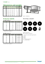
Installation
The air diffuser is normally suspended from the ceiling. An M8
pop nut, i.e. a threaded grommet that facilitates installation, is
in the centre of the top of the air diffuser. On the size 315 and
400 air diffusers, there are two M8 pop nuts for more stable
mounting, see figure 2 and 3.
Commissioning
Commissioning should be carried out with the diffuser face
mounted. Pull the measuring tubes and the damper adjustment
cords out of the air diffuser through one disc in the diffuser
face. Then connect the manometer to the correct measuring
tube(s): two blue tubes for supply air and one transparent tube
for extract air. The rated coefficient of performance of the air
register can be used in a calculation to determine the required
commissioning pressure. Conclude commissioning by adjusting
the damper to the correct blade position, tie a commissioning
knot in the damper cords to indicate the damper position. See
Figure 2. The K-factor is specified on the product’s identification
label and last in these instructions.
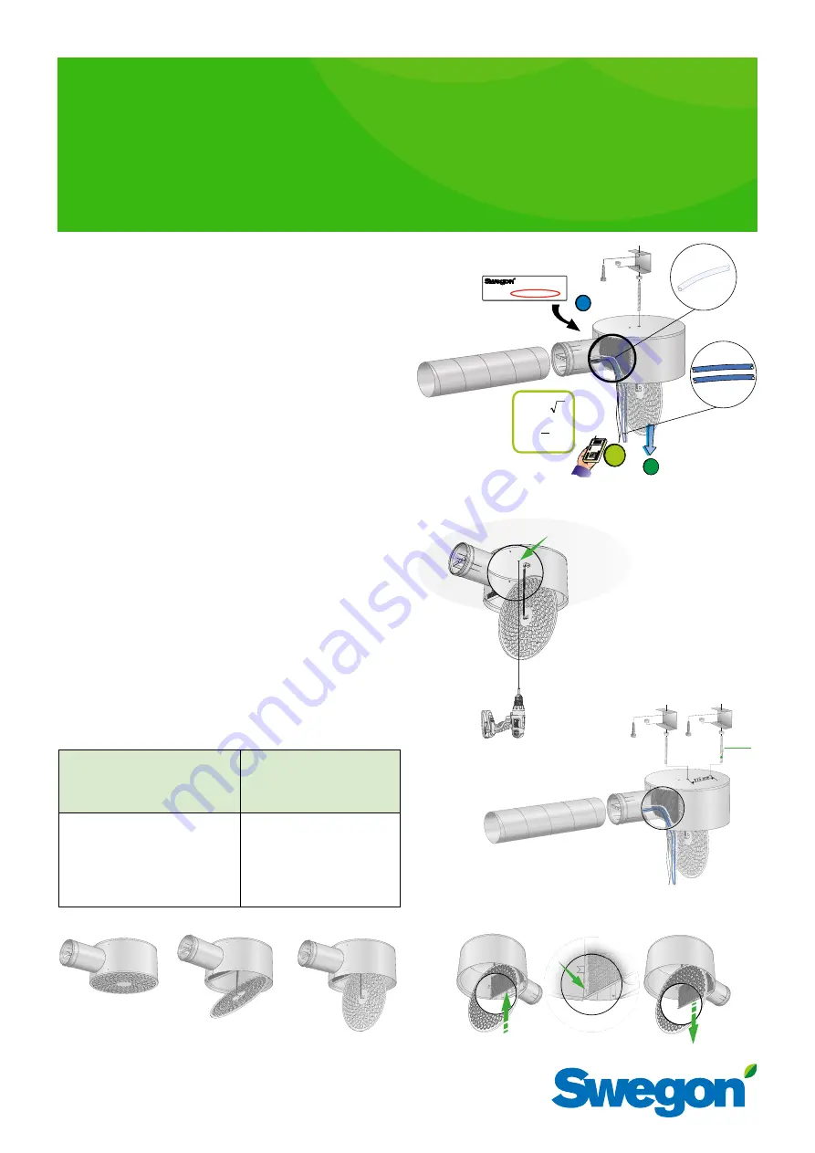
Maintenance
•
Clean the air diffuser if needed with lukewarm water and
dishwashing detergent added.
•
The duct system can be accessed and lightly pulling the
spring-loaded diffuser front downwards and then tilting,
see figure 1.
•
Dismantle the perforated air distribution plate located on
the inlet as shown in figure 4.
•
Loosen the damper in the inlet from its bayonet fastening
by rotating to the side.
Length of straight duct
Type of obstruction upstream of
Length of straight duct
upstream of the COLIBRI
Free
COLIBRI Free
m
2
= 5%
m
2
= 10%
One 90° bend
3 ·Ød
2 ·Ød
Two 90°bends in the same plane
4 ·Ød
2 ·Ød
Two 90° bends in alignment at
right angles to one another.
4 ·Ød
2 ·Ød
One 45° damper
6 ·Ød
3 ·Ød
One T-piece
4 ·Ød
3 ·Ød
m
2
= accuracy of the method according to NVG’s report T32:1982
Figur 1. Spring-loaded diffuser front.
Figure 4. Dismantling of the perforated air distribution plate.
Figure 3a. Alternative installation.
k-factor
q
= flow reading l/s
p
= current pressure reading (Pa)
k
= commissioning factor
Figure 2. Installation. Commissioning. Maintenance.
Applies only for
size 315 & 400
Figure 3b. Extra M8 pop nut, size 315 and 400.
COLIBRI
Free a
Installation – Commissioning – Maintenance
20181004


