background image

SERVICE MANUAL

20" COLOR TV/DVD

6520FDE

EWC20D4

MSD520FE

Summary of Contents for 6520FDE

Page 1: ...SERVICE MANUAL 20 COLOR TV DVD 6520FDE EWC20D4 MSD520FE ...

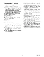
Page 2: ...he possible hazardous consequences of each way Consequently Funai has not undertaken any such broad evalua tion Accordingly a servicer who uses a service procedure or tool which is not recommended by Funai must first use all precautions thoroughly so that nei ther his safety nor the safe operation of the equipment will be jeopardized by the service method selected TABLE OF CONTENTS Specifications ...

Page 3: ...e worst condition that still might be considered acceptable In no case should a unit fail to meet limit specifica tions Description Condition Unit Nominal Limit 1 Over Scan 90 2 Linearity Horizontal 18 Vertical 10 3 High Voltage kV 25 Description Condition Unit Nominal Limit 1 Misconvergence Center m m 0 4 Corner m m 2 1 Side m m 1 4 2 Tint Control Range deg 30 3 Contrast Control Range dB 12 6 4 B...

Page 4: ... All Items are measured without pre emphasis unless otherwise specified 2 Power supply AC120 V 60 Hz 3 Load imp 100 K ohm 4 Room ambient temperature 25 C ITEM CONDITIONS UNIT NOMINAL LIMIT 1 Coaxial Digital Out 75 ohm load mVpp 500 100 ...

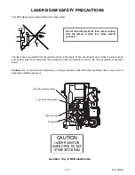
Page 5: ...ocation shown in the figure When checking the laser diode be sure to keep your eyes at least 30cm away from the pickup lens when the diode is turned on Do not look directly at the laser beam Caution Use of controls and adjustments or doing procedures other than those specified herein may result in hazardous radiation exposure Do not look directly at the laser beam coming from the pickup or allow i...

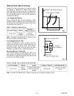
Page 6: ...rongs tied together and touch the other ohmme ter lead in turn to each tuner antenna input ex posed terminal screw and if applicable to the coaxial connector If the measured resistance is less than 1 0 megohm or greater than 5 2 mego hm an abnormality exists that must be corrected before the instrument is returned to the customer Repeat this test with the instrument AC switch in the off position d...

Page 7: ...ted to the ground side of the AC power source To confirm that the AC power plug is inserted correctly with an AC volt meter measure between the chassis and a known earth ground If a voltage reading in excess of 1 0V is obtained remove and reinsert the AC power plug in the opposite polarity and again measure the voltage potential between the chassis and a known earth ground b Some TV receiver chass...

Page 8: ...not contact sharp edged or pointed parts H When a power cord has been replaced check that 5 6 kg of force in any direction will not loosen it I Also check areas surrounding repaired locations J Be careful that foreign objects screws solder droplets etc do not remain inside the set K Crimp type wire connector When replacing the power transformer in sets where the connections between the power cord ...

Page 9: ...er cord plug prongs and externally exposed accessible parts RF terminals antenna terminals video and audio input and output terminals microphone jacks earphone jacks etc Measuring Method Power ON Insert load Z between B earth ground power cord plug prongs and exposed accessible parts Use an AC voltmeter to measure across both terminals of load Z See Fig 2 and following table Table 2 Leakage curren...

Page 10: ...pe around the Flat Pack IC to protect other parts from dam age Fig S 1 2 3 The Flat Pack IC on the CBA is affixed with glue so be careful not to break or damage the foil of each pin or solder lands under the IC when removing it 1 Removal With Hot Air Flat Pack IC Desoldering Machine a Prepare the Hot Air Flat Pack IC Desoldering Machine then apply hot air to Flat Pack IC about 5 6 seconds Fig S 1 ...

Page 11: ...lder from the foil of each pin of the Flat Pack IC on the CBA so you can install a replacement Flat Pack IC more easily b The I mark on the Flat Pack IC indicates pin 1 See Fig S 1 6 Make sure this mark matches the 1 on the CBA when positioning for installation Then pre solder the four corners of the Flat Pack IC See Fig S 1 7 c Solder all pins of the Flat Pack IC Make sure that none of the pins h...

Page 12: ...arged on the body Ground for Work Bench Be sure to place a conductive sheet or copper plate with proper grounding 1MΩ on the work bench or other surface where the semiconductors are to be placed Because the static electricity charge on the clothing will not escape through the body grounding band be careful to avoid contacting semiconductors to clothing Fig S 1 6 Example Pin 1 of the Flat Pack IC i...

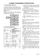
Page 13: ... Ground Wire before removing the Anode Cap 1 Disconnect the following Anode Cap CN1801 CN1802 CN505 CRT CBA CN1601 and CN1571 Then remove Tray Chassis Unit CAUTION 2 Electrostatic breakdown of the laser diode in the optical system block may occur as a potential difference caused by electrostatic charge accumulated on cloth human body etc during unpacking or repair work To avoid damage of pickup fo...

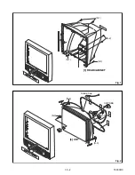
Page 14: ...1 5 2 T9000DC Fig 1 S 1 S 1 S 1 S 2 1 REAR CABINET Fig 2 S 3 S 3 3 CRT S 3 S 3 Anode Cap CRT CBA ...

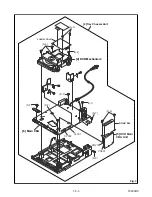
Page 15: ...1 5 3 T9000DC Fig 3 6 Main CBA 4 DVD Mechanism 5 DVD Main CBA Unit Loader Cover Shield Box 2 Tray Chassis Unit S 4 S 4 S 6 CN301 CN201 S 5 S 7 S 7 S 7 S 7 S 7 CL002 CL001 S 8 ...

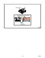
Page 16: ...1 5 4 T9000DC A Short the three short lands by soldering Either of two places Connector View for A Fig 4 DVD Mechanism ...

Page 17: ...1 5 5 T9000DC T Fig 5 SCREEN FOCUS CN505 CL501A CRT CBA DVD MAIN CBA UNIT CL002 CL001 CN1802 CN1601 CN1801 CL501B CN1571 T1571 AC CORD CN201 CN301 CNB1 CNA1 MAIN CBA ANODE CR GND SPEAKER SPEAKER ...

Page 18: ...0UD 6520FDE Part No NE221UD EWC20D4 Part No NE224UD MSD520FE Remove 4 screws from the back lid Fig 1 1 2 Remote control unit Part No NE220UD 6520FDE Part No NE221UD EWC20D4 Part No NE224UD MSD520FE Cut off pin 10 of the remote control microprocessor and short circuit pins 10 and 17 of the microproces sor with a jumper wire How to Set up the Service mode Service mode 1 Use the service remote contro...

Page 19: ...mote control unit so that the value of TINT TNT be comes 57 V TINT V TNT 1 Press PICTURE button on the service remote control unit Then select V TINT V TNT display 2 Press CH o p buttons on the service remote control unit so that the value of V TINT V TNT becomes 56 Note BRIGHT data value does not need to be adjust ed at this moment 3 1 C Trap Adjustment Purpose To get minimum leakage of the color...

Page 20: ... ser vice remote control unit seven times to show C ANG on the display 3 Y DL Time TV Adjustment Select 2 by pressing CH o p buttons on the service remote control Y DL Time EXT Adjustment Select 2 by press ing CH o p buttons on the service remote con trol Y SW LPF Adjustment Select 0 by pressing CH o p buttons on the service remote control Black Stretch Off Adjustment Select OFF by pressing CH o p...

Page 21: ...nd V P cyclically when 9 button is pressed 5 Press CH o p buttons on the service remote control unit so that the top and bottom of the mono scope pattern will be equal of each other 6 Turn the power off and on again using the main power button on the TV unit 6 H Position Adjustment Purpose To obtain correct horizontal position of screen image Symptom of Misadjustment If H Position is incor rect ho...

Page 22: ... Adjustment until the Hori zontal Line becomes pure white 10 Turn off and on again to return to normal mode Re ceive APL 100 white signal and Check Chroma temperatures become 9200K x 286 y 294 3 Note Confirm that Cut Off Adj is correct after this adjustment and attempt Cut Off Adj if needed 8 Sub Brightness Adjustment Purpose To get proper brightness Symptom of Misadjustment If Sub Brightness is i...

Page 23: ...Service remote control unit 1 Connect Frequency Counter to R1583 and ground 2 Set the unit to the VIDEO mode which is located be fore CH2 and no input is necessary Enter the Ser vice mode See page 1 6 1 3 Operate the unit for at least 20 minutes 4 Press 2 button on the Service remote control unit and select H ADJ mode 5 Press CH o p button on the Service remote con trol unit so that the display wi...

Page 24: ...hen done with steps 4 5 and 6 the horizontal line should be pure white if not then attempt the Cut off adjust ment again The following 2 adjustments normally are not attempted in the field They should be done only when replacing the CRT then adjust as a preparation 12 Purity Adjustment Purpose To obtain pure color Symptom of Misadjustment If Color Purity Adjust ment is incorrect large areas of col...

Page 25: ... at the center of the screen by rotating RB G C P Magnet See Fig 10 4 Fix the C P Magnets by tightening the Ring Lock 5 Remove the DY Wedges and slightly tilt the Deflec tion Yoke horizontally and vertically to obtain the best overall convergence 6 Fix the Deflection Yoke by carefully inserting the DY Wedges between CRT and Deflection Yoke Test point Adj Point Mode Input C P Magnet RB C P Magnet R...

Page 26: ... mode or press POWER button on the unit to turn the power off 8 Press SELECT or DVD PLAY button on the remote control unit to put the DVD player into DVD mode again 9 Press 1 2 3 4 and DISPLAY buttons on the remote control unit in that order Fig g appears on the screen 10 Press CLEAR button on the remote control unit Fig h appears on the screen When OK appears on the screen the factory default wil...

Page 27: ...NA1 TO AUDIO BLOCK DIAGRAM P ON H CL001 P DOWN Q1285 KEY 1 KEY 0 REMOTE RS1201 IC1202 MEMORY SCL 6 SDA 5 MAIN CBA TV MICON VIDEO CHROMA DEFLECTION SP MUTE 79 SP MUTE DVD A MUTE DVD A MUTE 65 78 59 60 61 64 12 67 66 70 7 CS 57 I2C OPEN RESET CS 11 SDATA 12 SCLK 10 DVD REMOTE 13 DVD MAIN POWER DVD MAIN POWER 77 28 18 40 69 AFT 76 EXT L EXT L AFT SDA SCL TO IF VIDEO BLOCK DIAGRAM 5 7V REG MCV 5 7V RE...

Page 28: ...MICON VIDEO CHROMA DEFLECTION SPOT KILL 72 WF2 WF17 WF18 CL002 DVD Y 1 DVD C 3 TP1733 DVD Y TP1734 DVD C TP1301 VIDEO OUT TO DIGITAL SIGNAL PROCESS BLOCK DIAGRAM DVD SECTION CNB1 CF1031 CF1032 VCO F B IC1001 IF SIGNAL PROCESS SAW FILTER VIF AMP VIDEO DET VCO 4 5MHz FILTER LPF IF AGC DET EQ AMP RF AGC AMP AFT 4 5MHz TRAP FM DET 16 11 13 18 6 17 4 2 7 1 9 TU1001 SF1001 IF AGC SDA SCL EXT CLK 1 11 5 ...

Page 29: ...1201 41 34 27 19 21 TUNER TUNER LINE LINE DVD DVD L CH R CH SPDIF 9 DVD AUDIO R 7 DVD AUDIO L 6 DVD A MUTE 5 TO DVD AUDIO BLOCK DIAGRAM DVD SECTION CNB1 TO SYSTEM CONTROL BLOCK DIAGRAM CL002 AUDIO R IN JK1702 AUDIO L IN JK1703 WF19 WF20 IC1801 AUDIO AMP SP MUTE TP1402 AUDIO R OUT AMP TP1401 AUDIO L OUT DVD A MUTE TP1403 DVD L OUT TP1404 DVD R OUT TO IF VIDEO BLOCK DIAGRAM TU AUDIO 6 1 2 IC1802 AUD...

Page 30: ...BA CRT CBA R G B HEATER ANODE GND V501 CRT GND FOCUS SCREEN JK501 HEATER 1 1 CN505 CL501A CL501B VIDEO SIGNAL TUNER LINE CN1571 160V 3 3 TO IF VIDEO BLOCK DIAGRAM 11 S F HV FOCUS VR SCREEN VR TO POWER SUPPLY BLOCK DIAGRAM H OUTPUT 1 3 5 4 5 4 3 1 WF8 WF7 WF14 WF15 WF13 WF10 WF11 WF9 WF12 RED AMP WF3 WF4 WF5 DVD VIDEO SIGNAL 7 7 RED 6 6 GREEN 8 8 BLUE ACL H DRIVE AFC V DRIVE V RAMP F B BLUE GREEN R...

Page 31: ...wn check to see that all components in the power supply circuit are not defective before you connect the AC plug to the AC power supply Otherwise it may cause some components in the power supply circuit to fail P ON 12V P ON 8V P ON 5V 2 5V SWITCHING Q1616 SWITCHING Q1606 Q1607 Q1612 1 2V REGULATOR IC1602 DVD MAIN POWER P ON H BACK UP P DOWN CL001 CNA1 AUDIO 5V TO SYSTEM CONTROL BLOCK DIAGRAM TO C...

Page 32: ...TUATOR DRIVE 147 TRAY IN SLD 75 SPDL 76 TRACKING DRIVE 148 FOCUS DRIVE 66 TO DIGITAL SIGNAL PROCESS BLOCK DIAGRAM FS FS TS TS TO DVD AUDIO BLOCK DIAGRAM 57 ADAC MD 56 ADAC MC 86 ADAC ML ADAC MC ADAC ML PCM SCLK 88 A MUTE ADAC MD A MUTE 163 PCM SCLK TRAY IN 3 SP 4 SP 5 TRAY IN 6 GND 7 SL 8 SL VREF RESET TO SYSTEM CONTROL BLOCK DIAGRAM TV SECTION CL001 73 RESET IC462 1 3 3 3V IC202 OP AMP 15 16 14 1...

Page 33: ... RAM INTERRUPT CONTROLLER WATCH DOG TIMER CPU I F TIMER DECODER I F CPU I F READ MEMORY DATA RAM DSP DECODER I O PROCESSOR INST ROM DATA RAM INST ROM SERIAL D A GENERAL I O INTERRUPT CONTROLLER TIMER WATCH DOG TIMER REMOTE CONTROL 32BIT CPU STREAM I F EXTERNAL MEMORY I F SDRAM ECC UMAC 114 115 116 117 132 131 134 133 129 130 126 124 125 123 83 DEBUG BCU INST RAM DATA RAM D A TO IF VIDEO BLOCK DIAG...

Page 34: ...4X 8X OVERSAMPLING DIGITAL FILTER FUNCTION CONTROLLER ENHANCED MULTI LEVEL DELTA SIGMA MODULATOR DAC LPF AMP L CH Q1004 R CH LPF AMP DAC SYSTEM CLOCK PCM BCK SPDIF PCM DATA PCM LRCLK ADAC MD ADAC MC ADAC ML PCM SCLK DVD MAIN CBA UNIT DATA AUDIO SIGNAL A MUTE 9 SPDIF 6 DVD AUDIO L 7 DVD AUDIO R 5 DVD A MUTE TO AUDIO BLOCK TV SECTION CL002 DVD AUDIO SIGNAL BUFFER Q1005 AMP T9000BLAD ...

Page 35: ...identified by the mark in the schematic diagram and the parts list Before replacing any of these components read the parts list in this manual carefully The use of substitute replacement parts that do not have the same safety characteristics as speci fied in the parts list may create shock fire or other hazards Capacitor Temperature Markings Capacitors and transistors are represented by the fol lo...

Page 36: ...se only original replacement parts which are listed with their part numbers in the parts list section of the service manual 4 Mode SP REC 5 Voltage indications on the schematics are as shown below Plug the TV power cord into a standard AC outlet 6 How to read converged lines 7 Test Point Information 2 3 1 5 0 2 5 0 TV mode Power on TV mode Power off DVD mode TV Section Unit Volts 5 0 The same volt...

Page 37: ...SIGNAL DVD VIDEO SIGNAL DVD AUDIO SIGNAL AUDIO TV LINE SIGNAL DATA AUDIO SIGNAL Main 1 6 Schematic Diagram TV Section 1 9 3 1 9 4 T9000SCM1 MAIN 1 6 Ref No Position IC1201 B 2 Q1285 B 1 Q1301 E 1 Q1303 D 1 Q1304 E 2 Q1305 D 4 TP1301 D 1 TP1304 E 4 TP1305 E 4 TP1501 E 4 TP1502 E 4 TP1503 F 4 IC TRANSISTORS TEST POINTS ...

Page 38: ... H1 H2 H3 H4 I1 I2 I3 I4 J1 J2 J3 J4 K1 K2 K3 K4 L1 L2 L3 L4 VIDEO TV LINE SIGNAL AUDIO TV LINE SIGNAL 1 9 5 1 9 6 T9000SCM2 Main 2 6 Schematic Diagram TV Section MAIN 2 6 Ref No Position IC1001 J 2 IC1202 J 2 ICS ...

Page 39: ... SIGNAL AUDIO TV LINE SIGNAL DATA AUDIO SIGNAL 1 9 7 1 9 8 T9000SCM3 Main 3 6 Schematic Diagram TV Section MAIN 3 6 Ref No Position IC1801 O 3 IC1802 N 3 CL002 R 2 CN1801 M 3 CN1802 M 4 TP1401 Q 2 TP1402 Q 2 TP1403 P 2 TP1404 P 2 TP1405 P 2 TP1732 Q 3 TP1733 O 1 TP1734 O 1 ICS CONNECTORS TEST POINTS ...

Page 40: ...25V 4A 125V CAUTION Fixed voltage or Auto voltage selectable power supply circuit is used in this unit If Main Fuse F1601 is blown check to see that all components in the power supply circuit are not defective before you connect the AC plug to the AC power supply Otherwise it may cause some components in the power supply circuit to fail MAIN 4 6 Ref No Position IC1601 T 2 Q1601 S 2 Q1602 T 2 Q1604...

Page 41: ... AA2 AA3 BB1 BB2 BB3 CC1 CC2 CC3 1 9 11 1 9 12 T9000SCM5 Main 5 6 Schematic Diagram TV Section MAIN 5 6 Ref No Position IC1602 Z 2 IC1603 AA 3 IC1604 Z 2 Q1609 Z 1 Q1615 BB 3 Q1619 AA 3 CL001 CC 3 ICS TRANSISTORS CONNECTOR ...

Page 42: ... 1 9 13 1 9 14 T9000SCM6 Main 6 6 CRT Schematic Diagram TV Section MAIN 6 6 Ref No Position IC1551 DD 3 Q1571 FF 2 Q1572 EE 3 Q1591 EE 2 CL501B GG 2 CN1571 EE 3 J2002 FF 2 TRANSISTORS CONNECTORS TEST POINT IC CRT Ref No Position Q511 HH 1 Q521 HH 2 Q531 HH 2 CN505 II 1 CL501A GG 2 CONNECTORS TRANSISTORS ...

Page 43: ...O AUDIO SIGNAL 1 9 15 1 9 16 T9000SCD1 DVD Main 1 3 Schematic Diagram DVD Section DVD MAIN 1 3 Ref No Position IC201 C 1 IC202 E 4 IC301 D 3 IC461 F 1 IC462 E 1 Q251 C 2 Q252 B 2 Q253 C 2 Q254 B 2 Q1001 E 2 Q1002 E 2 Q1003 F 2 CN201 A 3 CN301 A 1 CNA1 F 3 CONNECTORS ICS TRANSISTORS ...

Page 44: ...3 H4 I1 I2 I3 I4 J1 J2 J3 J4 K1 K2 K3 K4 L1 L2 L3 L4 DVD VIDEO SIGNAL DATA VIDEO AUDIO SIGNAL DATA AUDIO SIGNAL 1 9 17 1 9 18 T9000SCD2 DVD Main 2 3 Schematic Diagram DVD Section DVD MAIN 2 3 Ref No Position IC101 G 4 IC ...

Page 45: ...63 0 0 95 127 2 3 2 3 32 64 0 0 96 128 1 7 1 7 PIN NO PLAY STOP PIN NO PLAY STOP PIN NO PLAY STOP PIN NO PLAY STOP 129 2 3 2 3 161 3 4 3 4 193 225 3 4 3 4 130 2 3 2 3 162 0 0 194 226 131 2 3 2 3 163 1 8 1 8 195 227 132 2 4 2 3 164 0 0 196 3 4 3 4 228 133 2 4 2 4 165 1 7 1 8 197 229 0 0 134 2 4 2 4 166 1 7 1 7 198 230 135 2 3 2 3 167 3 4 3 4 199 231 3 4 3 4 136 2 3 2 3 168 0 0 200 232 1 3 1 6 137 2...

Page 46: ... Q4 R1 R2 R3 R4 DVD AUDIO SIGNAL DATA AUDIO SIGNAL DVD VIDEO SIGNAL 1 9 21 1 9 22 T9000SCD3 DVD Main 3 3 Schematic Diagram DVD Section DVD MAIN 3 3 Ref No Position IC103 N 3 IC501 N 4 IC502 Q 4 IC601 O 1 Q1004 Q 1 Q1005 Q 2 CNB1 R 1 ICS CONNECTOR TRANSISTORS ...

Page 47: ... used in this unit If Main Fuse F1601 is blown check to see that all components in the power supply circuit are not defective before you connect the AC plug to the AC power supply Otherwise it may cause some components in the power supply circuit to fail MAIN CBA Ref No Position Ref No Position IC1001 D 4 Q1615 D 2 IC1201 B 4 Q1616 D 4 IC1202 B 3 Q1619 C 3 IC1551 D 1 IC1601 E 3 CL001 B 1 IC1602 D ...

Page 48: ...ROUBLESHOOTING THIS TYPE POWER SUPPLY CIRCUIT A VARIABLE ISOLATION TRANSFORMER IS REQUIRED NOTE The voltage for parts in hot circuit is measured using hot GND as a common terminal CAUTION FOR CONTINUED PROTECTION AGAINST RISK OF FIRE REPLACE ONLY WITH SAME TYPE 4A 125V FUSE ATTENTION UTILISER UN FUSIBLE DE RECHANGE DE MÊME TYPE DE 4A 125V 4A 125V 1 9 25 BT9000F01011 CAUTION Fixed voltage or Auto v...

Page 49: ...Q521 Base WF13 Q531 Collector Q531 Base WF5 WF15 WF3 WF14 WF4 1 9 27 1 9 28 CRT CBA Top View TV Section CRT CBA Bottom View TV Section BT9000F01011 CRT CBA Ref No Position Q511 A 1 Q521 A 2 Q531 B 2 CN505 B 1 CL501A B 2 TRANSISTORS CONNECTORS ...

Page 50: ... WF7 GND 1DIV 5V 20µs Q1571 Base WF8 1DIV 20V 20µs Q531 Collector WF13 1DIV 0 2V 20µs CL002 Pin 1 WF17 1DIV 20V 20µs Q521 Collector WF15 1DIV 1V 0 5ms CL002 Pin 6 WF19 1DIV 1V 0 1µs CL002 Pin 9 WF20 1DIV 0 2V 20µs TU1001 Pin 8 WF16 GND WF1 WF20 Waveforms to be observed at Waveform check points Shown in Schematic Diagram Input NTSC Color Bar Signal with 1kHz Audio Signal WF1 WF16 DVD Video Power on...

Page 51: ...1B T1571 FBT CRT 1 2 3 4 5 CN1571 ANODE CL501A 7 6 4 4 3 2 1 W1601 AC CORD SP1802 SPEAKER L CH CN1801 SP1801 SPEAKER R CH CN1802 CL1802 CL1801 1 SP L 2 SP GND 1 SP R 2 SP GND GND 2 HEATER 1 160V 3 GND 4 8V 5 GREEN 6 RED 7 MAIN CBA BT9000F01011 CRT CBA BT9000F01011 BLUE 8 GND HEATER 160V GND 8V GREEN RED 8 BLUE CN301 3 4 TRAY IN GND SL 5 6 SP 7 SP 8 SL TRAY IN DRIVE CBA M SLED MOTOR M SPINDLE MOTOR...

Page 52: ...OL TIMING CHARTS Tray IN TL221 Sled Drive TP303 Disc Drive TP301 Focus Drive TP304 Tracking Drive TP302 0V 3 3V 0V 1 65V 0V 0V 0V 1 65V 1 65V 1 65V Tray Close Play Play Tray Open Tray Close Disc Rotation Play Disc Stop Tray Open ...

Page 53: ...al 31 V REG VCC DC 8 7V Input 32 FSC OUT Clock Output 3 58MHz 33 N U Not Used 34 AUDIO ATT OUT L Audio Output L 35 AUDIO ATT FILTER Audio Filter 36 AUX1 R IN DVD Audio Input R 37 V RAMP F B V Ramp Feed Back 38 V RAMP OUT Vertical Output 39 V RAMP CAP V Ramp OSC Capacitor 40 8 7V REG OUT 8 7V Output 41 AUDIO ATT OUT R Audio Output R 42 H VCO F B H Vco Feed Back 43 AFC FILT Horizontal AFC Filter 44 ...

Page 54: ...ed 72 SPOT KILL Spot Countermeasure 73 P SAFETY 1 Power Supply Protection 74 P SAFETY 2 Power Supply Protection 75 P SAFETY 3 Power Supply Protection 76 EXT L Switching External Input 77 DVD MAIN POWER Power On Signal to High for DVD 78 P ON H Output for P ON H 79 SP MUTE Audio Mute Signal 80 ACL CONT ACL Control Signal Pin No Signal Name Function ...

Page 55: ...4L02F WE2 CAT24WC02JI M24C02 WMN6 PQ070XF01SZ KIA431 AT 2SC2785 F H J 2SC3400 BA1F4M T BN1F4M T KRA103M KRC103M KTA1266 GR KTC3199 GR KTC3203 Y 2SA1015 GR TPE2 2SA1175 F 2SA950 O Y 2SC1627Y TPE2 2SC1815 GR TPE2 2SC2120 O TPE2 2SC2120 Y TPE2 2SC2482 TPE6 2SD400 E F KTA1267 GR KTA1271 Y KTC3198 GR AN15524A LA78040A TT2140LS YB11 2SC5885000RF M61273M8 062FP Note A Anode K Cathode E Emitter C Collecto...

Page 56: ... 7 A1 5 A1 6 A5 A1 1 A1X A1 2 A1 3 TL3 1B1 TB14 TB2 L2 TL4 TL4 TL2 TL1 TL1 TL1 TL1 TL1 TL1 TB10 TB1 TB12 L4 SP1801 CL1801 SP1802 CL1802 L4 B6 L4 L4 B6 A1 8 B2 B2 B2 B2 B1 B4 B4 CLN551 Scotch Tape 880 CRT CBA Scotch Tape 880 A4 V501 DG601 L551 B4 B4 W1601 TL2 TB4 TB5 MAIN CBA DVD MAIN CBA UNIT See Electrical Parts List for parts with this mark 6520FDE 1 15 1 1 15 2 T9000CEX ...

Page 57: ...1 15 3 T9000PEX Packing Packing Tape Packing Tape Packing Tape Packing Tape Packing Tape S1 S15 S3 S6 S14 X3 X4 X2 X7 X1 Tape S2 FRONT Packing Tape S4 S5 EWC20D4 EWC20D4 MSD520FE S4 6520FDE ...

Page 58: ...WX1T7180 005 WX1T7180 005 DG601 DEGAUSSING COIL F 054 LLBH00ZTM054 L1 SCREW P TIGHT 4X18 BIND HEAD GBMP4180 L2 SCREW TAPPING M4X14 DBU14140 L4 SCREW ASSEMBLED 12 M3X12 0EM406746 L7 SCREW P TIGHT 3X10 BIND HEAD GBKP3100 L551 DEFLECTION YOKE LLBY00ZSY010 LLBY00ZSY010 SP1801 SPEAKER S08F02B or DSD0808XQ010 SPEAKER J F097 C5 DSD0808DCP01 SP1802 SPEAKER S08F02B or DSD0808XQ010 SPEAKER J F097 C5 DSD0808...

Page 59: ...1204 CHIP CERAMIC CAP B K 0 015µF 50V CHD1JKB0B153 C1205 CHIP CERAMIC CAP B K 1000pF 50V CHD1JKB0B102 C1206 CHIP CERAMIC CAP B K 220pF 50V CHD1JKB0B221 C1207 FILM CAP P 0 001µF 50V J or CMA1JJS00102 FILM CAP P 0 001µF 50V J CA1J102MS029 C1209 CHIP CERAMIC CAP F Z 0 1µF 25V CHD1EZB0F104 C1214 CERAMIC CAP AX Y M 0 01µF 16V CCA1CMT0Y103 C1215 CHIP CERAMIC CAP F Z 0 01µF 50V CHD1JZB0F103 C1216 CHIP CE...

Page 60: ...GMASTL470 C1580 P P CAP 0 0082µF 1 6K J or CA3C822VC011 PP CAP 0 0082µF 1 6KV J or CT3C822MS039 Ref No Description Part No METALLIZED FILM CAP 0 0082µF 1 6KV J or CT3C822F7004 POLYPROPYLENE FILM CAP 0 0082µF 1 6KV CT3C822HJE16 C1581 CERAMIC CAP BN 1200pF 2KV or CCD3DKA0B122 CERAMIC CAP 1200pF 2KV or CA3D122PAN04 CERAMIC CAP RB 1200pF 2KV CA3D122TE006 C1584 ELECTROLYTIC CAP 1µF 160V M or CE2CMASDL1...

Page 61: ...JG001 CN1601 CONNECTOR BASE 2P TV 50P 02 V3 or J3TVC02TG002 CONNECTOR BASE 2P RTB 1 5 2P J3RTC02JG001 CN1801 STRAIGHT CONNECTOR BASE 00 8283 0212 00 000 or J383C02UG002 STRAIGHT PIN HEADER 2P 173981 2 1770258 Ref No Description Part No CN1802 STRAIGHT CONNECTOR BASE 00 8283 0212 00 000 or J383C02UG002 STRAIGHT PIN HEADER 2P 173981 2 1770258 DIODES D1001 SWITCHING DIODE 1SS133 T 77 or QDTZ001SS133 ...

Page 62: ...D0 6 P10 0 JW10 0T D1640 DIODE 1ZC33 or QDQZ0001ZC33 ZENER DIODE RD33FB QDQZ000RD33F D1641 ZENER DIODE MTZJT 775 6C or QDTC0MTZJ5R6 Ref No Description Part No ZENER DIODE DZ 5 6BSCT265 NDTC0DZ5R6BS D1650 SWITCHING DIODE 1SS133 T 77 or QDTZ001SS133 SWITCHING DIODE 1N4148 NDTZ001N4148 D1652 SWITCHING DIODE 1SS133 T 77 or QDTZ001SS133 SWITCHING DIODE 1N4148 NDTZ001N4148 D1653 SWITCHING DIODE 1SS133 T...

Page 63: ...RANSISTOR KTC3199 GR or NQS10KTC3199 TRANSISTOR KTC3198 GR or NQS40KTC3198 TRANSISTOR 2SC1815 GR TPE2 QQS102SC1815 Q1608 TRANSISTOR KTC3199 GR or NQS10KTC3199 TRANSISTOR KTC3198 GR or NQS40KTC3198 TRANSISTOR 2SC1815 GR TPE2 QQS102SC1815 Q1609 RES BUILT IN TRANSISTOR KRC103M or NQSZ0KRC103M RES BUILT IN TRANSISTOR 2SC3400 or 2SC3400Z RES BUILT IN TRANSISTOR BA1F4M T QQSZ00BA1F4M Q1610 TRANSISTOR 2S...

Page 64: ... R1430 CARBON RES 1 4W J 3 9k Ω RCX4JATZ0392 R1544 CHIP RES 1608 1 10W J 10k Ω RRXAJB5Z0103 R1551 CARBON RES 1 4W J 330 Ω RCX4JATZ0331 Ref No Description Part No R1552 CARBON RES 1 4W J 1 5k Ω RCX4JATZ0152 R1556 CARBON RES 1 4W J 1 Ω RCX4JATZ01R0 R1557 CARBON RES 1 4W J 470 Ω RCX4JATZ0471 R1558 CARBON RES 1 4W J 12k Ω RCX4JATZ0123 R1559 PCB JUMPER D0 6 P5 0 JW5 0T R1560 CARBON RES 1 4W J 2 7k Ω RC...

Page 65: ... CARBON RES 1 4W J 560 Ω RCX4JATZ0561 R1674 CARBON RES 1 4W J 22 Ω RCX4JATZ0220 R1681 CHIP RES 1608 1 10W J 10k Ω RRXAJB5Z0103 Ref No Description Part No R1682 CHIP RES 1608 1 10W J 22k Ω RRXAJB5Z0223 R1686 CARBON RES 1 4W J 4 7 Ω RCX4JATZ04R7 R1687 CARBON RES 1 4W G 5 6k Ω RCX4GATZ0562 R1688 CARBON RES 1 4W G 15k Ω RCX4GATZ0153 R1689 CARBON RES 1 4W G 18k Ω RCX4GATZ0183 R1690 CARBON RES 1 4W G 56...

Page 66: ...7 001 JYSL010RP002 PS1602 THERMISTOR ZPB45BL3R0A QNBZ45BL3R0A RS1201 REMOCON RECEIVE UNIT PIC 37042SR or USESJRSKK034 REMOCON RECEIVE UNIT PIC 26042SR 2 USESJRSKK032 SA1601 SURGE ABSORBER JVR 07N471K or NVQZVR07N471 SURGE ABSORBER CNR 10D471K or NVQZR10D471K Ref No Description Part No SURGE ABSORBER CNR 07D471K or NVQZR07D471K SURGE ABSORBER PVR 07D471KB NVQZ07D471KB SF1001 SAW FILTER SAFHM45M7VAA...

Page 67: ...CX4JATZ0152 R520 METAL OXIDE FILM RES 1W J 15k Ω or RN01153ZU001 METAL OXIDE FILM RES 1W J 15k Ω RN01153DP003 R521 CHIP RES 1608 1 10W J 33 Ω RRXAJB5Z0330 R522 CARBON RES 1 4W J 5 6k Ω RCX4JATZ0562 R525 CARBON RES 1 4W J 560 Ω RCX4JATZ0561 R526 CARBON RES 1 4W J 1 5k Ω RCX4JATZ0152 R527 CARBON RES 1 4W J 1 5k Ω RCX4JATZ0152 R530 METAL OXIDE FILM RES 1W J 15k Ω or RN01153ZU001 METAL OXIDE FILM RES ...

Page 68: ...6520FDE EWC20D4 MSD520FE T9000UA T9004UE T9008UJ 2004 03 31 ...

Reviews: