background image

TEHX-C &

TFHX SERIES

USER’S MANUAL

LCD CONTROLLER TYPE

TEHX-C &

TFHX SERIES

M-EFHX-LCD-04-E

(2003 .07)

Summary of Contents for TFHX Series

Page 1: ...TEHX C TFHX SERIES USER S MANUAL LCD CONTROLLER TYPE TEHX C TFHX SERIES M EFHX LCD 04 E 2003 07...

Page 2: ...PERATION BASICS DATA SETTING EMBROIDERY SETTING DESIGN DATA MANAGEMENT MANUAL OPERATION PARAMETER SETTING OUTLINE OF FUNCTIONS ELECTRO COMPONENT PARTS TROUBLESHOOTING MAINTENANCE APPENDIX Regarding op...

Page 3: ...njury fracture of a bone etc that leads to aftereffects or an injury that necessitates hospitalization or visits to a hospital over a long period 2 An injury that does not necessitate hospitalization...

Page 4: ...ATION 19 7 PANEL SOFTWARE INSTALLATION 20 8 OPERATION FLOW 22 9 VALUE INPUT 23 10 INPUT OF CHARACTERS 23 11 EXPLANATION ON THE SCREEN SCREEN 1000 24 12 EXPLANATION ON THE SCREEN SCREEN 1100 24 13 INSP...

Page 5: ...EXPLANATION ON THE SCREEN SCREEN 1400 66 2 THREAD TRIMMING TRACE 67 3 MANUAL OFFSET DESIGN START POSITION 68 4 FRAME ORIGIN MEMORY TFHX II TFHX IIC 69 5 FRAME ORIGIN MEMORY TEHX C TFHX TFHX C 70 6 PO...

Page 6: ...RING 89 42 BORING STEP 89 43 CORDING 89 45 NETWORK 89 46 SERIAL SPEED BPS 90 48 TABLE UP DOWN 90 49 BACKLASH X AXIS MM 90 50 BACKLASH Y AXIS MM 90 51 TOTAL STITCH COUNTER 91 52 DISPLAY OF M SHAFT STOP...

Page 7: ...LY SPECIFICATION 103 3 OPERATION PANEL BOX 104 CHAPTER 11 TROUBLESHOOTING 1 WHEN THE MACHINE STOPPED DURING OPERATION 106 2 IF TROUBLE OCCURS 109 CHAPTER 12 MAINTENANCE 1 WARNINGS AND CAUTIONS 112 2 C...

Page 8: ...CHAPTER 1 IMPORTANT WARNING ITEMS FOR SAFE OPERATION 1 CHAPTER 1 IMPORTANT WARNING ITEMS FOR SAFE OPER ATION GC02...

Page 9: ...d direct sunlight If the machine is exposed to direct sunlight over an extended period of time the machine body may be discol ored or deformed Put curtains or shades to the site to pre vent the machin...

Page 10: ...te the machine Only the persons who are sufficiently trained for the operation must operate the machine Do not have children access to vicinity of the machine The rear of the machine is not a working...

Page 11: ...nternal circuits causing fire electric shock and other troubles If water or other chemi cals enter a control unit shut off the power at the primary power source and contact your local distributor Duri...

Page 12: ...labels Do not detach the warning labels nor make them illegible by painting etc If a warning label is missed or damaged please consult your local distributor Sticking position of the warning labels Fo...

Page 13: ...tion No waterer las cabarets de saturated in power las manes etc circa de las pizzas en movement minters la maturing EST en functionaries WARNING ATENCION Exposed needles can cause severe injury Las a...

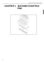
Page 14: ...CHAPTER 2 MACHINE CONSTRUCTION 7 CHAPTER 2 MACHINE CONSTRUC TION GC07...

Page 15: ...240 000 stitches Alternatively a 2HD floppy disk can hold up to 223 designs with approxi mately 480 000 stitches EDIT OF DESIGN DATA Design can be edited modified inserted deleted in 1 stitch units F...

Page 16: ...dery frame 8 Tension base switch 9 Thread breakage indicator lamp 10 Machine table 11 Main shaft motor 12 Stand 13 Bar switch box 14 Thread trimming cam box 15 Bar switch 16 Needle bar case 17 X axis...

Page 17: ...tch 8 Thread breakage indicator lamp 9 Machine table 10 Main shaft motor 11 Stand 12 Thread trimming cam box 13 Needle bar case 14 X axis motor 15 Power supply driver box 16 Power switch 17 Inverter 1...

Page 18: ...e 7 Y axis motor 8 Tension base switch 9 Thread breakage indicator lamp 10 Machine table 11 Main shaft motor 12 Stand 13 Thread trimming cam box 14 Needle bar case 15 X axis motor 16 Power supply driv...

Page 19: ...CAUTION If using the machine deviating from the conditions trouble may occur Model Superficial electrical power Electricity TFHX II TFHX IIC 1 3kVA 700W TFHX TFHX C 1 7kVA 920W TEHX C 2 5kVA 1 5kW Vol...

Page 20: ...speed Frame travel speed switching key switches manual frame travel speed to low speed mid dle speed When pressing the key at high speed speed will become low speed JOG REMOTE CONTROLLER It moves the...

Page 21: ...rt with all heads Switch at the bottom Needle bar does not move Embroidery is not performed Thread breakage indicator lamp During normal operation Green lit When upper thread breakage is detected Red...

Page 22: ...CHAPTER 3 OPERATION BASICS 15 CHAPTER 3 OPERATION BASICS GC02...

Page 23: ...turn it ON 2 EMERGENCY STOP SWITCH Pressing the emergency stop switch will cause the machine to stop at the fixed posi tion to turn OFF the power To perform cancellation follow the next procedure Rota...

Page 24: ...sed with 11 stitches and more the motion still continues and stops when moving it to the left again Hold it to the right Operation starts with inching Usual operation is performed when releasing it GC...

Page 25: ...a cleaning disk sold in the market If the head is dirty it could cause bad movement of reading writing of floppy disk Do not open the shutter To prevent the stored data from being erased slide the tab...

Page 26: ...beginning When turning ON the power separate your finger from the frame travel key 3 Installation Installation will start automatically and the screen for installation will appear When installation i...

Page 27: ...Just before End Code 30 Language 1 2 No Yes 0 6 0 8 0 999999 st 0 99999 cm 0 999 Designs 0 99 10000 st No Yes English Japanese Other Yes 0 8 0 0 0 0 No English 22 Return Stitches ATH 23 Tie Stitches...

Page 28: ...operation panel will be in a state as if it stopped for a few seconds Do not operate the panel in this moment Oth erwise installation may not be performed normally GC07 Screen 3000 6 12 2C 61 Max Revo...

Page 29: ...Screen 2000 Needle bar selection p 34 Data conversion repeat offset p 41 Data input from floppy disk p 29 Data input from serial connection p 30 Select the memory design When inputting data from an ex...

Page 30: ...n by frame travel key or jog remote controller that coordinate position will be displayed as value 10 INPUT OF CHARACTERS Treat it the same as key board Press this icon to register input characters It...

Page 31: ...sign of which data was converted Data conversion p 41 GC02 During stop During operation Screen 2000 Embroidery setting Screen 3000 Parameter Screen 1400 Manual operation Screen 1300 Color change Scree...

Page 32: ...vere injury Inspecting item Condition Action to take Cover Cover s depart from the machine Attach to the machine Thread Thread comes off Set thread Thread is broken Needle Needle s are bent Change the...

Page 33: ...CHAPTER 3 OPERATION BASICS 26...

Page 34: ...CHAPTER 4 DATA SET 27 CHAPTER 4 DATA SET GC02 Free Space...

Page 35: ...y area of memory designs and 16 and after designs are displayed at the next page 16 and after designs are stored at P2 Page switching icons will be added by the number of designs stored in memory It i...

Page 36: ...more will cause the design to be displayed 4 Completion of input After the input the data will be stored in the smallest value among vacant memory num bers of the screen 2000 GC02 Free Space 1 Screen...

Page 37: ...ut of characters p 23 3 Completion of input After the input the data will be stored in the smallest value among vacant memory num bers of the screen 2000 CAUTION Turn ON the switch of the external dev...

Page 38: ...sign When setting embroidery conditions press needle bar setting and data conversion to make setting Needle bar setting p 34 Data conversion p 41 2 Data set 3 Confirm GC02 Free Space 1 Screen 2000 Fre...

Page 39: ...CHAPTER 4 DATA SET 32...

Page 40: ...CHAPTER 5 EMBROIDERY SETTING 33 CHAPTER 5 EMBROIDERY SETTING GC02 1 2 3 1 2 3...

Page 41: ...the screen 2000 GC02 Free Space 1 2 3 7 8 12 Select the design to be set Deletion of needle bar step Setting of needle bar color Register Needle bar number key Needle bar step Needle bar number and ne...

Page 42: ...g selected will blink 2 Select the target needle bar number to be changed It is also possible to change other needle bars as the same way Selecting the target needle bar number will also change color...

Page 43: ...hen it is deleted the following needle bar steps will be moved up 3 Register Since the needle bar steps will be deleted by 1 step the machine will embroider the last step with the first step GC02 Free...

Page 44: ...copy the needle bar step being selected to insert It is possible to perform insertion up to the number of steps set in the stitch data 2 Register Change the inserted needle bar step to the needle numb...

Page 45: ...of needle bar steps will cause the following steps to be invalid and the machine will repeat steps before repeat in order 3 Register To cancel repeat of needle bar steps set a needle number to the ste...

Page 46: ...will not move Automatic offset p 47 2 Set offsetting at automatic color change Setting offsetting at automatic color change will cause the frame to move to the setting position of automatic offset wh...

Page 47: ...lect needle bar color and needle bar number key It is also possible to change other needle bars as the same way In addition it is possible to perform setting in reversed order of needle bar color and...

Page 48: ...0 GC02 100 100 0 1 1 X 0 0 0 0 Select the design to be set pp p To return to the screen 2000 Repeat information Automatic offset Numerical key Register Scale ratio in X direction Scale ratio in Y dire...

Page 49: ...Setting value 50 to 200 Pressing scale ratio of the Y direction will become the same value as the scale ratio of the X direction It is possible to change the scale ratio by inputting a value as it is...

Page 50: ...ut of value It is possible to input value by 1 degree unit Rotation by 45 unit Mirror image reversion Every pressing M will switch direction GC02 100 100 0 1 1 X 0 0 0 0 Select the design to be set pp...

Page 51: ...by the symbol of amount of design interval Unit of design interval mm 3 The number of designs to be arranged to Y direction GC02 100 100 0 1 1 X 0 0 0 0 Select the design to be set pp p 2 4 6 8 1 3 5...

Page 52: ...on Every pressing the icon will switch direction of priority X Y 6 Register GC02 7 8 100 100 0 4 2 X 75 5 58 2 pp q Screen 6000 9 100 100 0 4 2 Y 75 5 58 2 pp q Screen 6000 X priority 1 2 3 4 5 6 7 8...

Page 53: ...is mirror image conversion 180 rotation GC02 100 100 0 1 1 X 0 0 0 0 Select the design to be set pp p 100 100 0 5 2 X 40 5 58 2 pp q Screen 6000 1 2 1 2 3 4 5 6 7 8 9 10 100 100 0 5 2 X 40 5 58 2 pb q...

Page 54: ...frame type is changed the current set ting will be reset Offsetting at automatic color change p 39 It makes the frame move to the offset posi tion at color change points when the machine performs embr...

Page 55: ...set 1 per form registration once more without frame travel 3 Input and registration of offset 2 Registration of offset 2 will cause offset 1 become a middle position at frame travel Registration of of...

Page 56: ...CHAPTER 6 DESIGN DATA MANAGEMENT 49 CHAPTER 6 DESIGN DATA MANAGE MENT GC02...

Page 57: ...2200 How to call the screen Design data management screen Editing the design data that has been set the data set will be canceled GC02 Floppy disk writing Previous state Overwriting of design name De...

Page 58: ...FLOPPY DISK WRITING How to call the screen 1 Insert the floppy disk 2 Select the floppy disk writing 3 Input a file name Input of characters p 23 4 Confirm GC02 Select the design to edit 1 Screen 2200...

Page 59: ...OF DESIGN NAME How to call the screen 1 Select the overwriting of design name 2 Overwriting of design name Input of characters p 23 3 Completion GC02 Select the design to edit 1 Screen 2200 Screen A00...

Page 60: ...GN DATA MANAGEMENT 53 4 DELETION OF MEMORY DESIGN How to call the screen 1 Select deletion of design 2 Confirm 3 Completion GC02 Selecting the design to delete 1 Screen 2200 Screen 2200 OK 2 Screen 20...

Page 61: ...APTER 6 DESIGN DATA MANAGEMENT 54 5 DELETION OF ALL DESIGNS How to call the screen 1 Select the deletion of all designs 2 Confirm 3 Completion GC02 1 Screen 2200 Screen 2200 OK 2 Screen 2000 Free Spac...

Page 62: ...be removed to prevent thread com ing off or thread breakage 2 Cleanup processing Applicable cleanup stitch lengths are 0 4 to 0 9 mm As this function searches a corre sponding stitch and makes the pr...

Page 63: ...code the machine will search data existing near for ward or backward of the function code to display Scroll Data by 10 stitches of forward backward will be displayed GC02 0 1 2 3 4 5 6 7 8 9 0 12 1 1...

Page 64: ...OW Low speed revolution HIGH High speed revolution JUMP Jump STOP Stop color change Stitch GC02 Select the design to edit 0 1 2 3 4 5 6 7 8 9 0 12 1 11 11 11 11 12 12 9 0 6 15 9 5 5 5 2 11 1 0 1 Scree...

Page 65: ...0 will be inserted GC02 Select the design to edit 0 1 2 3 4 5 6 7 8 9 0 12 1 11 11 11 11 12 12 9 0 6 15 9 5 5 5 2 11 1 0 Screen 8000 0 1 2 3 4 5 6 7 8 9 0 12 1 11 11 11 11 12 12 9 0 6 15 9 5 5 5 2 11...

Page 66: ...e following ones will be moved up GC02 Select the design to edit 0 1 2 3 4 5 6 7 8 9 0 12 1 11 11 11 11 12 12 9 0 6 15 9 5 5 5 2 11 1 0 Screen 8000 0 1 2 3 4 5 6 7 8 9 0 12 1 11 11 11 11 12 12 9 0 6 1...

Page 67: ...code p 57 GC02 Select the design to edit 0 1 2 3 4 5 6 7 8 9 0 12 1 11 11 11 11 12 12 9 0 6 15 9 5 5 5 2 11 1 0 Screen 8000 0 1 2 3 4 5 6 7 8 9 0 12 1 11 11 11 11 12 12 9 0 6 15 9 5 5 5 2 11 1 1 12 Sc...

Page 68: ...E 4274st T G004 STARS 568st G005 MOON 10205st G007 LILY 4401st T T G001 DOG 1233st T G006 CAR01 8976st G002 FLAG 879st T G003 HORSE 4274st T G004 STARS 568st G005 MOON 10205st G007 LILY 4401st T T Sel...

Page 69: ...t T T G001 DOG 1233st T Screen 4000 G001 DOG 1233st T G006 CAR01 8976st G002 FLAG 879st T G003 HORSE 4274st T G004 STARS 568st G005 MOON 10205st G007 LILY 4401st T T 1 Free Space Screen 4000 G001 DOG...

Page 70: ...07 LILY 4401st T T 1 Free Space BC1 Message The disk is not formatted Format the disk OK G001 DOG 1233st T G006 CAR01 8976st G002 FLAG 879st T G003 HORSE 4274st T G004 STARS 568st G005 MOON 10205st G0...

Page 71: ...CHAPTER 6 DESIGN DATA MANAGEMENT 64...

Page 72: ...CHAPTER 7 MANUAL OPERATION 65 CHAPTER 7 MANUAL OPERATION GC03 Xa 43 2 Ya 276 1...

Page 73: ...ing on models and specifications Thread trimming Trace Manual offset Design start position Frame origin memory Power resume Automatic lubrication option Table up down TEHX C multi head machine Sequin...

Page 74: ...0 WARNING When performing this operation do not put your hands under the needle or on the machine table If your hands are under the needle or on the machine table you may be injured by the needle or t...

Page 75: ...8 Design start position The frame will move to start position of design WARNING When performing this operation do not put your hands under the needle or on the machine table If your hands are under th...

Page 76: ...is not possible to use jog remote control ler 3 Memorize the origin When the position of the origin is searched will switch to o When the origins of both axes are searched make the machine memorize t...

Page 77: ...turning off the power 2 Execute Execution of frame origin memory will cause the frame to move automatically to search the origin When the machine memorizes the origin the frame will return to the ori...

Page 78: ...es are searched make the machine memorize the positions When the machine memorizes the origin the frame will return to the position where the power was shut off WARNING When performing this operation...

Page 79: ...ame will return to the position where the power was shut off and power resume operation will finish WARNING When performing this operation do not put your hands under the needle or on the machine tabl...

Page 80: ...ION SYSTEM OPTION How to call the screen 1 Select automatic lubrication system It activates the automatic lubrication system to supply oil to the machine 2 Execute GC03 Xa 43 2 Ya 276 1 Screen 1400 1...

Page 81: ...l be dis played p 106 2 Up down operation Move up down the table using frame travel key It is not possible to use jog remote control ler 3 End WARNING When performing this operation do not put your ha...

Page 82: ...When performing this operation do not put your hands under the needle or on the machine table If your hands are under the needle or on the machine table you may be injured by the needle or the moving...

Page 83: ...n of amount of moving stitches Every pressing of stop code searching will search the next stop code It is also possible to input the number of stitches by numerical keys Execution will perform frame b...

Page 84: ...lor change set the parameter 1 Auto Color Change to No When Yes is set needle bar will return to the original needle bar at start of embroidery even if performing manual color change p 81 1 Select the...

Page 85: ...CHAPTER 7 MANUAL OPERATION 78...

Page 86: ...Change AC 2 Auto Start AS 3 A S in the Same Color 4 A S after Auto Data Set 5 Main Shaft Inching 6 M Shaft Inching after ATH 7 Auto Jump mm 8 Jump Convert No Yes No Yes No Yes No Yes 0 1 2 3 4 5 6 7 8...

Page 87: ...ce will display P4 P5 Pressing P5 twice will ADJ pressing ADJ twice will display INF 1 Auto Color Change AC 2 Auto Start AS 3 Auto Start in the Same Color 4 A S after Auto Data Set 5 Main Shaft Inchin...

Page 88: ...and after color change automatic start will be per formed It is possible to make setting when Yes is set to 2 Auto Start Yes Automatic start is performed No Automatic start is not performed Yes Yes No...

Page 89: ...the number of set times and more consecutively it converts the con secutive jump codes to frame stepping Frame stepping moves the frame with the main shaft kept stopping No does not make jump conversi...

Page 90: ...17 Under T Detection Unit 0 2 4 6 8 18 Under T D Step Ratio 40 50 60 70 80 19 ATH No Yes 20 Picker Timing Tail Length 340 359 0 60 deg When starting the machine after frame back make the machine stop...

Page 91: ...Picker Timing Tail Length 340 359 0 60 deg It adjusts sensitivity of thread breakage detection When the setting value becomes bigger the sensitivity will become higher 40 50 60 70 80 No No No 600 2 4...

Page 92: ...0 Yes 0 8 0 0 0 0 No Japanese 21 Select Under T Trimming mm 0 5 10 20 30 A 22 Return Stitches ATH 1 2 23 Tie Stitches No Yes 24 Tie Return Stitch Length mm 0 6 0 8 25 Preset Halt Stitch 0 999999 st 2...

Page 93: ...d at stop of the machine 0 makes no stop It is effective when 36 Lubrication is set to No 0 99 10000st 0 Yes 0 8 0 0 0 0 No Japanese 21 Select Under T Trimming mm 0 5 10 20 30 A 22 Return Stitches ATH...

Page 94: ...origin at the end of embroidery Yes To move No Not to move Yes No Yes 1 0 0 Yes 200 250 No 0 No No No 31 F B F F Stitch Unit st 1 3 5 32 Satin Stitch Data to add mm 1 0 1 0 33 Auto Origin Return No Y...

Page 95: ...equipped with the machine or not It is not displayed in TFHX C TFHX 2C and TEHX C Yes Equipped No Not equipped No 1 0 0 Yes 200 250 No 0 No No No 31 F B F F Stitch Unit st 1 3 5 32 Satin Stitch Data...

Page 96: ...Backlash X Axis mm 0 5 0 5 50 Backlash Y Axis mm 0 5 0 5 Select whether cording device is equipped with the machine or not Yes Equipped No Not equipped Yes No No No Step1 No No 38400 No 0 0 0 0 41 Bor...

Page 97: ...Boring No Yes 42 Boring Step Step1 Step3 43 Cording No Yes 45 Network No Yes 46 Serial Speed bps 9600 19200 38400 48 Table Up Down No Yes 49 Backlash X Axis mm 0 5 0 5 50 Backlash Y Axis mm 0 5 0 5 Ye...

Page 98: ...edle Position 54 PANEL Software Install No Yes 56 Stop at Lower D Point No Yes 57 Frame Travel Key 4 8 58 Adjust M Shaft Stop Position 5 5 Display the needle position 465 0 No No 4 0 51 Total Stitch C...

Page 99: ...top Position 53 Display of Needle Position 54 PANEL Software Install No Yes 56 Stop at Lower D Point No Yes 57 Frame Travel Key 4 8 58 Adjust M Shaft Stop Position 5 5 Perform adjustment when stop pos...

Page 100: ...ot applied 1000 15 6 2C Auto No 61 Max Revolution rpm 500 1200 64 Number of Needles 3 6 9 12 15 18 65 Number of Heads 2 3 4r 4d 5 6 7 8 66 Model 2 2C L LC N NC 67 Frame Drive Mode Auto 210 69 CPU Soft...

Page 101: ...ual frame drive mode and type to reduce looping It is not possible to perform setting in Auto Usual frame drive mode 210 200 Frame drive mode to reduce loop ing 200 Max 850rpm Upper limit to low speed...

Page 102: ...CHAPTER 9 OUTLINE OF FUNCTIONS 95 CHAPTER 9 OUTLINE OF FUNCTIONS GC02...

Page 103: ...EVERSION It is possible to make reversion based on Y axis GC02 X 150 Y 180 Design start position When all of enlargement reduction rotation and mirror image reversion are set the data processing will...

Page 104: ...ft illustra tion is minus direction X direction priority Y direction priority 4 5 6 1 2 3 2 4 6 1 3 5 GC02 Converted arrangement arranges and repeats the design as it is set as the initial setting in...

Page 105: ...osition A B A GC07 When there is no middle position C the frame will move directly to the offset start position D This function moves the embroidery frame forward automatically at the end posi tion of...

Page 106: ...ondition Offsetting at automatic color change is set automatic offset is set Yes is set to Automatic color change AC automatic start AS and ATH of parameter B A Middle position B Color change point C...

Page 107: ...stance b Stitch width c 1 2 of the setting value GC02 This function makes the frame move along the outer circumference of the design that has been set Trace makes the frame move to each apex of the ou...

Page 108: ...CHAPTER 10 ELECTRO COMPONENT PARTS 101 CHAPTER 10 ELECTRO COMPONENT PARTS GC02...

Page 109: ...the machine to mal function 1 Y axis driver Driver card 3 pieces LED on each card 2 X axis driver Driver card 3 pieces LED on each card 3 LED A lamp that indicates condition of the driver Lights in g...

Page 110: ...screws 1 6 spots and take out the front cover 2 of the power supply driver box Remove the connector 3 of the fan motor located at the box cover 2 Short connector Slide the position of the short connec...

Page 111: ...not change setting of the DIP switch 1 DIP switch SW1 2 FDD 3 Backlight inverter 4 CPU E card 5 Touch panel cable extension card 6 Frame travel switch card 7 RISC card 8 Touch panel 9 Regulator card...

Page 112: ...CHAPTER 11 TROUBLESHOOTING 105 CHAPTER 11 TROUBLESHOOTING GC02 228...

Page 113: ...the frame to the rearmost 251 Lubrication pump oil is insufficient Supply oil to the tank 281 The target needle position is not detected even after 15 seconds after start of color change Return the n...

Page 114: ...osition sensor 383 There was no needle position signal during rotation of the main shaft Check the potentiometer needle position sensor 3A1 There is abnormality in thread trimming driver Check the joi...

Page 115: ...machine 1B2 Stop due to a stop code 1B3 Stop due to stop code 1 1B4 Stop due to thread trimming code 1B6 Stop due to an automatic free setting offset code 1C1 Stop due to the bar switch stop switch P...

Page 116: ...eration panel Jump error Incorrect positioning of parts related to needle bar drive system Adjust the attaching position of the needle bar reciprocator set with the upper dead point stopper Design dis...

Page 117: ...ROUBLE OCCURRED This work cuts off head where trouble occurred as a temporary measure Procedure of works 1 Remove the tension base cover 1 2 Remove the connector 3 from the tension base card 2 3 Conne...

Page 118: ...CHAPTER 12 MAINTENANCE 111 CHAPTER 12 MAINTENANCE GC02...

Page 119: ...which were removed for maintenance operation CAUTION Perform daily maintenance in the specified schedule If the daily maintenance is not observed the machine may fail to operate correctly Since the lo...

Page 120: ...intenance operation attach all covers etc which were removed for maintenance operation CAUTION If the slits of the power supply driver box and or the filter of the main shaft motor is clogged temperat...

Page 121: ...use only Tajima s genuine SF oil or equivalent 150 spindle oil ISO viscosity grade VG18 Lubrication Points Lubricating Cycle 1 Rail section of rotary hook Every 3 to 4 hours of operation 2 Needle bar...

Page 122: ...e recommended goods mineral oil based lithium grease or equivalent Greasing spot Greasing cycle 1 Presser foot cam 2 Take up lever drive cam 3 Roller of take up lever 4 Bevel gear Once 3 months 5 Case...

Page 123: ...en performing the repairs of the machine Before starting the work be sure to disconnect the primary power supply to the machine Before disconnecting the primary power supply turn OFF the power switch...

Page 124: ...TERMINOLOGY TERMINOLOGY FD11...

Page 125: ...ME A kind of embroidery frames It holds cut cloth material of some extent of size to be stretched BORING DEVICE A device that makes hole s on the cloth material by knife attached to the needle bar to...

Page 126: ...DSW The abbreviation of Dual in Package Switch Refer to the DIP switch EMBROIDERY FRAME A general term of frames that hold material to be embroidered such as cloth leather etc END CODE There are the c...

Page 127: ...tion of Intelligent Machine Management 2 card It mainly controls movements of the machine INCHING Very slow rotation of the main shaft when the machine starts or before it stops JUMP Not to activate n...

Page 128: ...NUMERICAL KEYS Numerical keys of 0 to 9 OFFSET START POSITION A free setting position that makes the embroidery frame wait temporarily in offset setting ORIGIN The position where start or frame forwa...

Page 129: ...n X or Y data at the same time TAJIMA TWO WAY NETWORK SYSTEM System that performs centralized control of plural machines using a personal computer It can transmit design data or receive running condit...

Page 130: ...e embroidery frame move to right and left directions against the front of the embroidery machine Y DATA The data that makes the embroidery frame move front rear direction Y direction by the Y axis dri...

Page 131: ...TERMINOLOGY...

Page 132: ...ELECTRO RELATIVE DRAWING ELECTRO RELATIVE DRAWING GC02...

Page 133: ...H card TFHX C L spec M C TFHX L spec M C Power supply driver box Emergency stop switch Touch panel CPU E card RISC card Inverter X axis motor Start switch Stop switch ATH solenoid Thread trimming sole...

Page 134: ...Main shaft motor Surge Inverter CN3 Brake resistor Line noise Filter Terminal protector Noise Filter Power Emergency stop switch In case of single phase 26V 26V 26V 26V Breaker Electro component part...

Page 135: ...d B Head card I F card A ATH card TFHX C TFHX Start switch Stop switch Power supply driver box Emergency stop switch Touch panel CPU E card RISC card Inverter X axis motor Y axis motor Start switch St...

Page 136: ...resistor Line noise filter 3 Terminal protector Noise filter Power Emergency stop Switch In case of single phase 26V 26V 26V 26V Breaker Electro component parts box Upper thread Upper thread Upper thr...

Page 137: ...ch Table up down unit Emergency stop switch Color change motor Touch panel Inverter Stop switch Tension base card CPU E card RISC card X axis motor Y axis motor Joint card Head card I F card A ATH car...

Page 138: ...ieces 14 head M C 3 pieces 16 head M C 4 pieces 18 head M C 5 pieces 20 head M C 6 pieces 5 3 phase M C and Standard M C M spec M C of single phase Upper thread Upper thread Upper Upper thread Upper t...

Page 139: ...ELECTRO RELATIVE DRAWING...

Page 140: ...anual without our permission is prohibited Manufactured by Tokai Industrial Sewing Machine Co Ltd NO 1800 Ushiyama cho Kasugai Aichi pre 486 0901 Japan Telephone 568 33 1161 Fax 568 33 1191 Distribute...

Reviews: