background image

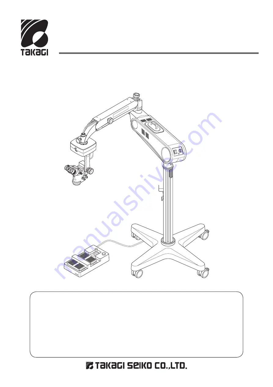
Operating Microscope

MODEL OM-8

Instruction Manual

IM(OM-8)E Rev.1

We would like to thank you for purchasing our Operating Microscope.  Read 

this manual thoroughly before use, understand the contents, and handle this 

instrument safely and correctly
● Do not use this instrument in any other way than described in this manual.

● Keep this manual handy for future reference.

● Contact our distributor or our Sales Department if this manual is lost or 

damaged.

OM8-T01

Summary of Contents for OM-8

Page 1: ...roscope Read this manual thoroughly before use understand the contents and handle this instrument safely and correctly Do not use this instrument in any other way than described in this manual Keep th...

Page 2: ......

Page 3: ...lies where the instrument is used in an appropriate environment and where it is serviced and maintained as prescribed Disposal If disposing of the projection lamps and fuses do so in accordance with t...

Page 4: ...nee is not in discomfort 3 Where any abnormality is found in the instrument or the examinee take necessary actions such as making sure that the examinee is safe and turning the instrument off 4 During...

Page 5: ...sunlight 4 in a place exposed to corrosive gas 5 on an unstable surface 6 near thermal appliances Install the instrument on a level surface Notes Before Use Check that the instrument operates normall...

Page 6: ...and Their Functions 10 16 Installation 17 25 Installing the Main Unit Connecting the Power Cable Changing the Pedal Layout of the Type I Foot Controller Preparations for Operation 26 29 Adjusting the...

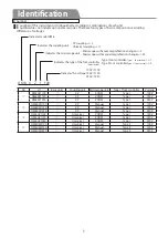
Page 7: ...ion changer Z Microscope with manual magnification changer M Type I Foot controller Type Foot switch 1 Type II Foot controller Type Foot switch 2 100V 100 120V 120 230V 230 No Basic units Coupling uni...

Page 8: ...1230 100V OM8XM1100 120V OM8XM1120 230V OM8XM1230 100V OM8UZ1100 120V OM8UZ1120 230V OM8UZ1230 100V OM8UM2100 120V OM8UM2120 230V OM8UM2230 OM8 T02 Basic units Note voltage needs to be selected Select...

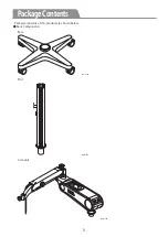
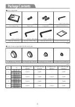
Page 9: ...3 PackageContents Package contents of this product are shown below Basic Components OM8 T03 Base Post OM8 T04 Arm unit OM8 T05...

Page 10: ...croscope unit Manual microscope unit OM8 T07 Foot controller unit Foot switch unit Type I Foot controller unit Type Foot switch unit OM8 T08 OM8 T09 Type Foot controller unit Type Foot switch unit Cou...

Page 11: ...nts User s choice components Disinfectant caps Disinfectant caps Z01019 OM8 T13 Disinfectant caps Z01020 Disinfectant caps O09079 Disinfectant caps O04065 1 No Disinfectant caps Z01019 Disinfectant ca...

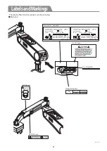
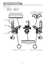
Page 12: ...sandMarkings The labels affixed on this product are shown below Main unit OM8 T14 Manufacturer s Nameplate CAUTION Label Fuse Rating Label Voltage Rating Label Light Heavy CAUTION CAUTION Label WARNIN...

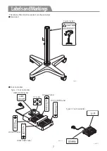
Page 13: ...5 LOCK EACH HANDLES AND FOLD THE COUNTER BALANCED ARM TO MOVE THE UNIT AS SHOWN BELOW CAUTION Caution label OM8 T16 LAMP ON OFF X Y FOCUS UP Label FOCUS DOWN Label ZOOM DOWN Label ZOOM UP Label LAMP O...

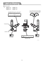
Page 14: ...O N RE D RE FLE X O F F RE D RE FLE X Magni cation power and scale of the diopter setting engraved Scale of the PD interpupillary distance setting engraved Stroke mark Center mark Objective lens ON l...

Page 15: ...D interpupillary distance setting engraved Stroke mark Center mark Objective lens ON label OFF label OM8XM1100 OM8XM1120 OM8XZM230 OM8UM1100 OM8UM1120 OM8UM1230 ID O FF RED REF LEX O N RED REF LEX RE...

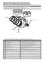
Page 16: ...Mounting ring To be loosened to remove or replace the eyepiece 4 Diopter adjustment ring To be rotated to adjust the diopter 5 Eye caps Can be folded where required e g where examiner wears spectacles...

Page 17: ...itch To return the shaft to the center 11 Weight To bring the unit into balance 12 Microscope rotation lock handle To adjust and fix the rotation torque for the microscope 13 Level indicator Shows the...

Page 18: ...llumination ON OFF lever The red reflex illumination is applied when the lever is pushed The illumination is blocked when the lever is pulled out 20 Objective lens Can be replaced by other objective l...

Page 19: ...ed when the lever is pushed The illumination is blocked when the lever is pulled out 20 Objective lens Can be replaced by other objective lenses with each focal length 22 Set screw To fix the binocula...

Page 20: ...stment handle 28 Lamp unit 29 Light intensity control knob 30 Lamp ON OFF switch 31 Power plug 32 Fuse No 1 33 Fuse No 2 34 Power socket for foot switch 35 Voltage switch 36 Arm shaft 37 Lamp arm swiv...

Page 21: ...e No 2 Fuse for the lamp 34 Power socket for foot switch To connect with the power connector for the foot switch 35 Voltage switch To select the input voltage 36 Arm shaft Inserts in the stand pole 37...

Page 22: ...part 44 Caster with stopper Two casters with stoppers in the rear 45 Base To insert and fix the pole in 46 Caster Two casters without a stopper in the front 47 Hanger Hangs the foot switch on the lowe...

Page 23: ...e adjustment handle as that could upset the adjustment ofthecounter balancedarmandadverselyaffectthefunctioningoftheunit When installing the microscope unit do not turn the balance adjustment handle a...

Page 24: ...18 Installation 2 Insert the bottom of the post into the base s boss OM8 T27 Insert 3 Using the accessory 6 mm hexagonal wrench tighten the fastening bolt securing the post in the base OM8 T28 Tighten...

Page 25: ...se the arm unit will possibly be dropped OM8 T29 Insert OM8 T30 Screws Tighten 2 Using the accessory 4 mm hexagonal wrench tighten the two screws in the post OM8 T31 Tighten Installing the Coupling Un...

Page 26: ...on its upper side 3 Tighten the two locking screws with accessory 1 5 mm hexagonal wrench securing the X Y coupling unit in place OM8 T31 Tighten Installing the Microscope Unit Use the microscope uni...

Page 27: ...same direction Then tighten the two hexagonal bolts with the 4 mm hexagonal wrench securing the suspension arm OM8 T36 Tighten Alignment screw Insert Installing the Binocular 1 Align the binocular un...

Page 28: ...es Removing the counter balanced arm s cover 1 Turn the vertical movement lock handle counterclockwise remove the handle 2 Remove the four screws on the arm s cover with a screwdriver 3 Remove the arm...

Page 29: ...able holders OM8 T42 Connecting the cables 1 Remove the bottom cover by removing the two screws Remove two screws OM8 T43 2 Put the cables through the counter balanced arm s boss Pass through OM8 T44...

Page 30: ...ontroller to the arm unit where patients are absent 1 Connect the foot switch connecter to the foot switch power socket of the arm unit 2 Tighten the attaching screws Tighten the screws OM8 T47 OM8 T4...

Page 31: ...sult When disconnecting the power cable from the socket pull it out by the plug Do not pull it out by the cord Voltage selector OM8 T48 OM8 T49 Power Cable Power Plug Dedicated Wall Outlet Insert CAUT...

Page 32: ...terbalanced arm s balance cannot be adjusted properly as the arm drops by itself discontinue the use of the OM 8 immediately After making all the attachments and connecting the cables as as described...

Page 33: ...amp arm swivel locking handle 2 If necessary turn the counter balance arm s and the lamp arm swivel locking handles clockwise until they stop locking the arms Centering Prior to operation set the micr...

Page 34: ...diopters of the microscope s eyepieces to your eyesight If you wear glasses fold back the eyecaps of the eyepieces and then adjust the diopters For adjusting the diopters have clean white paper ready...

Page 35: ...Adjust the microscope to your build and working conditions putting it at an angle that is comfortable for you to use 1 Supporting the microscope with your left hand with your right hand turn the oper...

Page 36: ...g the arm in place After completion the Preparations for Operation operate the OM 8 as follows OM8 T39 Loosen OM8 T59 Zoom switch for high mag Magni cation display window 3 Step on the front side of t...

Page 37: ...n or off OM8 T62 X Y lever Lamp on o switch OM8 T63 Fiter plate 7 If necessary select a filter by pushing or pulling out the filter plate You can choose from the blue cut retina shield and only perman...

Page 38: ...switch for rise Focus switch for descent 6 Operating the foot switch unit s X Y lever move the microscope s visual field to the target location To operate the X Y lever tilt it in the direction that...

Page 39: ...illumination The red reflex illumination on off lever is used to either apply or block the red reflex illumination The lever on The coaxial illumination togeter with red reflex illumination is availa...

Page 40: ...ation Before replacing the lamp turn off the power and wait for the lamp to cool The instrument and the lamps are hot immediately after use burn injuries may result Use lamps with the ratings O91 02 1...

Page 41: ...rating Then put the fuse holder back in place and secure it by turning it clockwise with a plus screwdriver 4 Using a minus screwdriver rotate the fuse holder 90 counterclockwise and pull out the fuse...

Page 42: ...thinner benzine acetone toluene and ethyl acetate or bleach to clean the instrument This may damage the painted surfaces or the resin components Scheduled Servicing This instrument Operating Microsco...

Page 43: ...s to the instrument securely See Connecting the Power Cord under Installation on Page 25 Check to see if the lamp is blown and that the other spare lamp unit is in working order If the spare lamp ligh...

Page 44: ...adjustment range 55mm to 75mm Diopter adjustment range 5D Focusing stroke 30mm 2 X Y Coupling unit X Y movement stroke 25 mm in both X and Y directions 3 Illumination unit Illumination method Coaxial...

Page 45: ...39 ExternalViewsandDimensions Manual Microscope Unit 1565 858 5 200 640 665 380 1045 164 640 OM8 T73...

Page 46: ...40 ExternalViewsandDimensions Zoom Microscope Unit 164 1565 858 5 200 640 640 1045 665 380 OM8 T74...

Page 47: ...Unit with 175mm Objective S01 14SE Straight Binocular Tubes Video Beam Splitter O08 13 NTSC O08 14 PAL O06 19SE Coaxial Binocular Microscope S11 01 Beam Splitter TV Camera Adaptor with C Mount O08 11...

Page 48: ...10P M Return switch Origin sensor Y axis motor Origin sensor X axis motor J8 CN 4R P J7 RM15TRH 8S RM15TP 8P CN 6R P ZOOM Motor FOCUS Motor Transformer 105 0133 CN 5R P CN 7R P CN 8R P J1 J3 J2 J9 J10...

Page 49: ...degreeofprotectionagainstelectricshock Type B Operation mode of the device Continuous operation Device classification Deviceclassification Installation location Indoor away from direct sunlight Temper...

Page 50: ...nearby electronic equipment RF emissions CISPR 11 Class B The OM 8 is suitable for use in all establishments including domestic establishments and those directly connected to the public low voltage po...

Page 51: ...mmon mode 1kV differential mode 2kV common mode Mains power quality should be that of a typical commercial or hospital environment Voltage dips short interruptions and voltage variations on power supp...

Page 52: ...m fixed RF transmitters as determined by an electromagnetic site survey a should be less than the compliance level in each frequency range b Interference may occur in the vicinity of equipment marked...

Page 53: ...ration distance according to frequency of transmitter m 150 KHz to 80 MHz d 1 2 P 80 MHz to 800 MHz d 1 2 P 800 MHz to 2 5 GHz d 2 3 P 0 01 0 12 0 12 0 23 0 1 0 38 0 38 0 73 1 1 2 1 2 2 3 10 3 8 3 8 7...

Page 54: ...in EU TAKAGI OPHTHALMIC INSTRUMENTS EUROPE LTD Greenheys Unit 46 Manchester Science Park Pencroft Way Manchester M15 6JJ United Kingdom Tel 44 0 161 209 9360 Fax 44 0 161 209 9282 e mail info takagie...

Page 55: ...made to ensure the smooth operation of this product and accuracy of information in this manual please contact us should you notice any problems errors ambiguities or omissions Contact our distributor...

Page 56: ......

Reviews: