background image

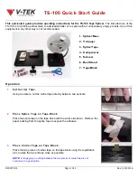
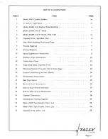
Summary of Contents for 424

Page 1: ...TAPE READER Revised 4 1 62 MANUAL MODEL 424 This publication reproduced with the permission of TALLY REGISTER CORPORATION 1310 Mercer Street Seattle 9 Washington D 1066...

Page 2: ...ram Spark Suppression Waveforms Standard Tape Dimensions Lubrication Chart Tape Read Head Exploded View Checking Contact Pressll e with a Gram Gage Correct Positioning ior Star Wheels Escapement Adjus...

Page 3: ...ure 26 27 28 29 LIST OF ILLUSTRATIONS Continued Tape Read Head Parts List Reel Drive Mechanism Parts List End of Tape Switch Parts List Commutator Unit Parts List Title Page 28 30 32 33 SEATTLE Page i...

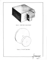
Page 4: ...Figure 1 Model 424C Console Reader 7 Figure 2 6 and 10 Tape Reels S ATTlt Page iv...

Page 5: ...Figure 3 Model 424PF Reader With Fanfold Tape Handling Figure 4 Model 424 PR Reader With 6 Tape Reels SEATTLE Page v...

Page 6: ...TAN I l RIVE BELT 1 REEL DRIVE BELT R H REEL DRIVE MECHANlSM LH i 0 L 1 I 1 4 I I r 1_ I I I 4 J _ J I l I I 1 I j I r J ri I I __l ___J I t i I r v __ r i I 1 _____ __ r LIFT LEVER TAPE TAPE TENSION...

Page 7: ...ching Action 3 3 Timing 3 4 Cycle Length Limitations 3 5 Terminations 3 6 Spark Suppression 3 7 Contact Ratings INSTRUCTIONS FOR USE 4 1 Paper Tape Standards and Channel Identification 4 2 Threading T...

Page 8: ...ent armature pole face must be wiped clean of all lubricant d Drive Motor Lubricate drive motor bearings using rust and oxidation inhibited oil SAE 20 grade 5 2 Read Head Service 5 2 1 Trouble Shootin...

Page 9: ...POINT NO LUBRICANT l i MINERAL OILI S AE 20 2 TALLY GREASE A SILICONE OIL I 3 50 cs Figure 12 Lubrication Chart SE A Tl l Page 11...

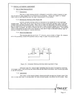
Page 10: ...I I TALLY S ATTl Page 12...

Page 11: ...adjusting eccentric 29 The movable contact wires 34 must be free to move up and down in the gap be tween the fixed contacts 31 Improper alignment may be corrected by carefully bending the movable cont...

Page 12: ...pping the tape first forward and then in the reverse direction If the switching in both directions is not within the 7 7 14 millisecond zone loosen the recessed head clamp screw and turn the adjusting...

Page 13: ...ICKED POSITION I TIP CLEARANCE 010 003 100 GRAMS TENSION Figure 16 Escapement Adjustments 6 0 TAPE SPLICING Care should be taken in splicing tapes to help prevent err oneous reading If a rough joint i...

Page 14: ...ly or if no per foration exists the star wheel will roll over the splice and yet be in position to read a character on the next step Allow approximately 1 2 inch for splice overlap b Taper the ends of...

Page 15: ...tch actuator When no tape is present the switch contacts will be in the normally closed position One sensing switch is positioned on each side of the capstan so that end of tape is indicated whether t...

Page 16: ...to the capstan velocity and whose phase is adjustable and related to the tape hole and star wheel reading position Switch closure and phase angle is ad justed to fulfill specific customers requiremen...

Page 17: ...gure 22 illustrates the flexibility of these adjustments 7 2 4 Adjustment When both brushes are set so as to engage their commutator segment contacts at exactly the same moment the switch closure angl...

Page 18: ...odel Panel Model Tape Handling Facility No Tape Handling Fan Fold Tape Handling No Tape Handling Fan Fold Tape Handling Reel Tape Handling The panel model series are mounted on an anodized aluminum pa...

Page 19: ...Coil D r i v e v_o_i_t_a_g_e__ __ Q_n Coil _ Commutator DC Voltage Contact Switching Capstan rpm a specified by cu tomer 1 No Hole 111111m111111 Hole 111111 111111 Tine Figure 22 Commutator Timing Dia...

Page 20: ...ers This approach is ideally suited for customers using several readers in one location by stocking one spare read head the spare parts on hand are then held to a minimum 8 0 PARTS ORDERING AND PARTS...

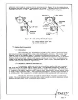
Page 21: ...s I J ____ J _ __ 1 I _ CJ O 0 E _ I TALLY SEATTLE Page 22...

Page 22: ...ion Spring Hinge Pin Stripper Plate L H Outboard Bearing Bracket Stripper Plate R H Connector Bracket Connector Fuse Capacitor Clamp Capacitor Motor Chassis Fuse Holder Bussman Fuse Slow Blow 1 2 amp...

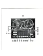
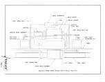
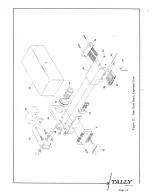
Page 23: ...C ool Figure 24 Model 424C Tape Reader SEATTLE Page 24...

Page 24: ...Clamp Motor 1 30 hp 1725 rpm Rear Cover Connector Assembly Cover Fan Cooling Pulley 8 tooth Drive Belt Base Plate Pulley 16 T Base Extension Bracket Fanfold models only Fanfold Box Bracket 2 used Fanf...

Page 25: ...TALLY SEATTLE Page 26...

Page 26: ...Retaining Ring 2 used 5103 18 11 Terminal Strip 1 4456 12 Horizontal Spacer 2 2065 13 Capstan Shaft 1 3553 14 Secondary Drive Shaft 1 3551 1 15 Idler Bevel Gear 1 3554 16 Rear Bearing Plate 2 1997 17...

Page 27: ...TALLY SE ATTLE Page 28...

Page 28: ...Adjusting Screw 10 32 x 3 8 29 Bushing Pivot Pin 1 3755 30 Pivot Clamp 1 3756 31 Fixed Contact Assembly 2 1686 32 Starwheel Lever Spacer 1 5090 33 Read Head Contact Insulator 1 3752 34 Movable Contac...

Page 29: ...and brake mechanism actuated by tape tension arms Both mechanisms are driven by belts from the capstan drive assembly Since the units are bi directional either reel can be the take up or supply side...

Page 30: ...ts List Part Name Spider Bevel Gear 2 used on L H Bevel Gear Spacer L H only Bevel Gear L H only Bevel Gear w Set Screw R H only Bevel Spur Gear Differential Spider Retaining Ring Brake Gear Part No 2...

Page 31: ...rive Mechanism R H Complete Tension Arm 6 Reels Tension Arm 10 Reels Retaining Ring 2 used Tension Arm Roller Post Spring Washer Drive Pulley Double Groove Drive Belt L H 6 Reels Drive Belt R H 6 Reel...

Page 32: ...e accorded the manufacturer s warranty This warranty does not extend to any of our products which have been subjected to misuse neglect accident or improper installation or application Obligation unde...

Page 33: ...e 29 Commutator Unit Parts List Part Name Commutator Assembly Circuit Board Brush Holder Brush Holder Brush 2 used Terminal Strip Screw 14 40 x 1 4 Fillister Head 3 Part No 2 2639 2 2189 2 2148 2 2149...

Page 34: ...oil Resistance O ohms Peak Inverse Voltage 80 volts Coil Inductance 60 mh Escapement coils 50 ohms or 220 ohms Contact pressure should be 10 20 grams instead of 14 22 Add index No 25 Pulley 16 tooth P...

Page 35: ...Page 4...

Page 36: ...ition is sensed the star wheel rides the tape on two of its points and the movable contact is i witched to the upper normally closed N C position When a hole is sensed with the tape moving in either d...

Page 37: ...sferred from the normally closed to the normally open position However due to the mechanical delay designed into the reader contact switching occurs between 7 and 14 milliseconds after the drive pulse...

Page 38: ...in Milliseconds Timing shown is for maximum reading rate of 60 cps 30 Drive pulse duration 4 5 0 5 ms with rise time less than 0 5 ms Dip in coil current curve marks the magnet armature striking the p...

Page 39: ...hes Capstan Commutator j __ Grn Tape Channel 8 7 6 1 2 3 4 5 Gry Gry Com A Lower UpperD B Gry E t J u Vlt F K u N u Blu L u TRAI x Red d Red V y b Orn 4 Orn Z c g Ylw YlW d Ylw h k 1 lJj Grn Contact p...

Page 40: ...wever contacts are replaceable 4 0 INSTRUCTIONS FOR USE 4 1 Paper Tape Standards and Channel Identification The Model 424 Reader is designed to read any perforated tape that conforms to industry stand...

Reviews: