background image

Manual

Shuttle-train controls

HELIOS

Version D.C.

for analogue

d.c. model

railway layouts

Item no.

51-02046 | 51-02047

Version A.C.

for analogue

a.c. model

railway layouts

Item no.

51-02056 | 51-02057

t

a

ms elektronik

n n n

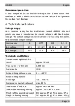
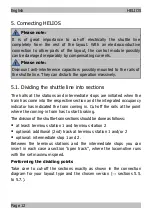
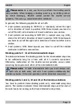
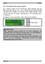
Summary of Contents for HELIOS

Page 1: ...Shuttle train controls HELIOS Version D C for analogue d c model railway layouts Item no 51 02046 51 02047 Version A C for analogue a c model railway layouts Item no 51 02056 51 02057 tams elektronik...

Page 2: ...Connections for 2 rail systems non compliant to NEM 631 24 5 7 Connections for 3 rail systems 30 6 Adjusting and programming HELIOS 36 6 1 Determining the version 36 6 2 Setting the locomotives drivi...

Page 3: ...rly the chapter on safety instructions and the checklist for trouble shooting You will then know where to take care and how to prevent mistakes which take a lot of effort to correct Keep this manual s...

Page 4: ...ers for the connections connections to rails and points 0 25 mm When connecting points at the terminus stations which are no stop points you need to switch the points a bistable relay 12 V e g item no...

Page 5: ...azards Touching powered live components touching conducting components which are live due to malfunction short circuits and connecting the circuit to another voltage than specified impermissibly high...

Page 6: ...en can cause any of the accidents mentioned above because they are inattentive and not responsible enough Children under the age of 14 should not be allowed to work with this module In schools trainin...

Page 7: ...us stations single or double track In addition you can build two intermediate stops or an intermediate station with two tracks It is not possible to build only one intermediate stops or a single track...

Page 8: ...tives max 3 locomotives max 4 locomotives Note on version 3 With the current software status 12 2018 silvery marking on the processor it is not possible to control version 3 Please contact us if you i...

Page 9: ...e phases acceleration braking and halt has to be set individually for each locomotive and each station Additionally the individual maximum speed for each locomotive has to be set When beginning the sh...

Page 10: ...edure varies depending on the version the number of locomotives on the shuttle line and the starting positions of the locomotives Basically the following applies When operating 2 locomotives which sta...

Page 11: ...fficient for switching the points Recommended output voltage Nominal size Z N TT H0 0 1 2 d c voltage 12 V 14 16 V 18 20 V 20 22 V a c voltage 10 V 12 V 16 V 18 V Technical specifitations Current cons...

Page 12: ...the train has come into the respective section and the integrated occupancy indicator has indicated the train coming in Cut off the rails at the point where the coming in train has to start braking Th...

Page 13: ...avel to define a new section 3 rail systems With these layouts you have to cut off the middle conductor to define a new section Dividing points 4 11 at the intermediate stops The distance between the...

Page 14: ...rements of the connected points section 4 The polarity is of no importance when connectin only HELIOS 1 Voltage supply 2 Please note When connecting several devices to the same transformer all connect...

Page 15: ...voltage supply for the other track When mounting neither stop points nor bistable relays both tracks will be supplied with power constantly Connection of a bistable relay at terminus stations 1 and 2...

Page 16: ...W plus and a bistable relay at the terminus stations 1 and 2 Hint The diagram equally applies to 2 rail systems not according to NEM 631 e g LGB layouts With 3 rail systems you have to devide the midd...

Page 17: ...iodes Connect them according to the diagrams Cut the rail that way that all current collectors driving the motor have passed the cut off before the train reaches the end of the rails Connection of a s...

Page 18: ...2 rail systems compliant to NEM 631 Version 1 2 rail system compliant to NEM 631 1 Voltage supply 2 Voltage supply 3 4 5 6 7 8 9 10 20 11 Terminus station 1 12 13 14 Terminus station 2 15 Open track...

Page 19: ...to NEM 631 1 Voltage supply 2 Voltage supply 3 Points 1 switching contact 1 4 Points 1 return conductor 5 Points 1 switching contact 2 6 7 8 9 10 20 11 Terminus station 1 12 13 14 Terminus station 2...

Page 20: ...ints 3 switching contact 1 10 Points 3 return conductor 20 Points 3 switching contact 2 11 Terminus station 1 12 13 14 Terminus station 2 15 Open track 1 16 Open track 2 17 18 19 Note on version 3 Wit...

Page 21: ...tact 1 Points 2b switching contact 2 7 Points 2a and 2b return conductor 8 Points 2a switching contact 2 Points 2b switching contact 1 9 10 20 11 Terminus station 1 12 Intermediate stop 1 13 Intermedi...

Page 22: ...tching contact 2 6 Points 2a switching contact 1 Points 2b switching contact 2 7 Points 2a and 2b return conductor 8 Points 2a switching contact 2 Points 2b switching contact 1 9 10 20 11 Terminus sta...

Page 23: ...tact 1 Points 2b switching contact 2 7 Points 2a and 2b return conductor 8 Points 2a switching contact 2 Points 2b switching contact 1 9 Points 3 switching contact 1 10 Points 3 return conductor 20 Po...

Page 24: ...ail systems non compliant to NEM 631 Version 1 2 rail system non compliant to NEM 631 1 Voltage supply 2 Voltage supply 3 4 5 6 7 8 9 10 20 11 Terminus station 1 12 13 14 Terminus station 2 15 Open tr...

Page 25: ...nt to NEM 631 1 Voltage supply 2 Voltage supply 3 Points 1 switching contact 1 4 Points 1 return conductor 5 Points 1 switching contact 2 6 7 8 9 10 20 11 Terminus station 1 12 13 14 Terminus station...

Page 26: ...Points 3 switching contact 1 10 Points 3 return conductor 20 Points 3 switching contact 2 11 Terminus station 1 12 13 14 Terminus station 2 15 Open track 1 16 Open track 2 17 18 19 Note on version 3 W...

Page 27: ...ontact 1 Points 2b switching contact 2 7 Points 2a und 2b return conductor 8 Points 2a switching contact 2 Points 2b switching contact 1 9 10 20 11 Terminus station 1 12 Intermediate stop 1 13 Interme...

Page 28: ...witching contact 2 6 Points 2a switching contact 1 Points 2b switching contact 2 7 Points 2a und 2b return conductor 8 Points 2a switching contact 2 Points 2b switching contact 1 9 10 20 11 Terminus s...

Page 29: ...ontact 1 Points 2b switching contact 2 7 Points 2a und 2b return conductor 8 Points 2a switching contact 2 Points 2b switching contact 1 9 Points 3 switching contact 1 10 Points 3 return conductor 20...

Page 30: ...5 7 Connections for 3 rail systems Version 1 3 rail system 1 Voltage supply 2 Voltage supply 3 4 5 6 7 8 9 10 20 11 Terminus station 1 12 13 14 Terminus station 2 15 16 Outer conductor 17 Open track...

Page 31: ...1 Voltage supply 2 Voltage supply 3 Points 1 switching contact 1 4 Points 1 return conductor 5 Points 1 switching contact 2 6 7 8 9 10 20 11 Terminus station 1 12 13 14 Terminus station 2 15 16 Outer...

Page 32: ...ching contact 1 10 Points 3 return conductor 20 Points 3 switching contact 2 11 Terminus station 1 12 13 14 Terminus station 2 15 16 Outer conductor 17 Open track 18 19 Note on version 3 With the curr...

Page 33: ...contact 1 Points 2b switching contact 2 7 Points 2a und 2b return conductor 8 Points 2a switching contact 2 Points 2b switching contact 1 9 10 20 11 Terminus station 1 12 Intermediate stop 1 13 Interm...

Page 34: ...switching contact 2 6 Points 2a switching contact 1 Points 2b switching contact 2 7 Points 2a und 2b return conductor 8 Points 2a switching contact 2 Points 2b switching contact 1 9 10 20 11 Terminus...

Page 35: ...contact 1 Points 2b switching contact 2 7 Points 2a und 2b return conductor 8 Points 2a switching contact 2 Points 2b switching contact 1 9 Points 3 switching contact 1 10 Points 3 return conductor 20...

Page 36: ...onnections have been made correctly 6 1 Determining the version By inserting jumpers you determine if the shuttle line has intermediate stops or not how many locomotives are run on the shuttle line fr...

Page 37: ...arting tracks 1 and or 2 3 and 4 open Operation Locomotive 1 and locomotive 2 shuttle in turns between the two terminus stations When setting only one locomotive for the shuttle service the operation...

Page 38: ...on 2 track 3 to terminus station 1 track 1 3 Locomotive 2 runs from terminus station 1 track 2 to terminus station 2 track 3 and so forth When setting less than 3 locomotives for the shuttle service t...

Page 39: ...rvice between the two terminus stations at the same time The locomotives stop at the two intermediate stops for the set hold time but at least until the oncoming locomotive has reached the intermediat...

Page 40: ...minus stations On their outward journey they stop at the one intermediate stop and on their return journey at the other stop 5 open with intermediate stop 2 and 3 inserted Starting tracks 2 and 3 1 an...

Page 41: ...motive 1 and 3 start at the two terminus stations at the same time The locomotives stop at the two intermediate stops for the set hold time but at least until the oncoming locomotive has reached the i...

Page 42: ...time The locomotives stop at the two intermediate stops for the set hold time but at least until the oncoming locomotive has reached the intermediate stop as well Afterwards the operation will be rep...

Page 43: ...ning the starting tracks The settings made for a locomotive s driving characteristics are saved for a specific starting track For that reasyon you have to determine from which tracks of the terminus s...

Page 44: ...main unaffected by the changes 6 3 Setting the maximum speed Choosing a locomotive for programming Locomotive 1 Starting positiong track 1 inserted Locomotive 2 Starting positiong track 2 1 inserted L...

Page 45: ...tarting track Setting the maximum speed By turning trimpot 1 you alter the maximum speed Saving the settings By pressing the push button you save the set maximum speed Please note The settings can onl...

Page 46: ...nserted Locomotive 3 Starting positiong track 3 2 and 5 inserted Locomotive 4 Starting positiong track 4 1 2 and 5 inserted Choosing the station Tablet on the next page You can put locomotives 1 and 2...

Page 47: ...Tablet on the previous page Setting the duration of accelarating and braking Preparation Turn the trimpots to left limit stop Insert a jumper on array 5 Choose a locomotive and a station for programm...

Page 48: ...Trimpot 1 Accelarating Trimpot 2 Braking The changes will be implemented immediately Saving the settings By pressing the push button you save the set duration of accelarating and braking Please note T...

Page 49: ...otive 3 Starting positiong track 3 2 and 6 inserted Locomotive 4 Starting positiong track 4 1 2 and 6 inserted Choosing the station Tablet on the next page You can put locomotives 1 and 2 or locomotiv...

Page 50: ...he locomotive Tablet on the previous page Setting the halt time Preparation Turn the trimpots to left limit stop Insert a jumper on array 6 Choose a locomotive and a station for programming by inserti...

Page 51: ...ing mode the halt time is reduced to of the halt time in future operation in order to reduce waiting time Saving the settings By pressing the push button you save the set halt time Please note The set...

Page 52: ...the LEDs 2 to 4 flashing slowly Afterwards switch off the voltage supply again 6 7 Choosing the starting mode You start the shuttle service either immediately after switching on the voltage supply or...

Page 53: ...er having eliminated the short circuit or reduced the current consumption you have to put all locomotives back on their starting tracks It is not possible to restart the shuttle service from the posit...

Page 54: ...op When points have been switched externally the setting of the points will be adjusted at this moment Make sure that the points are not switched externally after the locomotives have started As a con...

Page 55: ...ng tracks and restart operation The locomotive does not run with the set driving characteristics Possible cause When starting shuttle operatation the locomotive has not started from its assigned start...

Page 56: ...ast page Repairs You can send in a defective module for repair address on the last page In case of guarantee the repair is free of charge for you With damages not covered by guarantee the maximum fee...

Page 57: ...mponents as well as the function of the parts according to the parameters in not mounted state We guarantee the adherence to the technical specifications when the kit has been assembled and the ready...

Page 58: ...orised electrician Make no changes to the original parts and accurately follow the instructions connection diagrams and PCB layout included with this manual Use only original spare parts for repairs 2...

Page 59: ...HELIOS English Page 59...

Page 60: ...on and tips n http www tams online de n n n n Warranty and service n Tams Elektronik GmbH n Fuhrberger Stra e 4 DE 30625 Hannover n fon 49 0 511 55 60 60 fax 49 0 511 55 61 61 n e mail modellbahn tams...

Reviews: