background image

For Power Connection, In-Line Splice Connection,  

T-Splice Connection, or End Termination Applications


Terminator


TM

 ZP

Power Connection Kit

INSTALLATION PROCEDURES


Tel: 

+44


(0)191 490 1547 

Fax: 

+44


(0)191 477 5371


Email: 

northernsales@thorneandderrick.co.uk


Website: 

www.heattracing.co.uk 

                  www.thorneanderrick.co.uk


Summary of Contents for Terminator ZP

Page 1: ...plice Connection or End Termination Applications TerminatorTM ZP Power Connection Kit INSTALLATION PROCEDURES Tel 44 0 191 490 1547 Fax 44 0 191 477 5371 Email northernsales thorneandderrick co uk Website www heattracing co uk www thorneanderrick co uk ...

Page 2: ...ding 6 1 Banding Guide 7 1 Terminal Blocks with DIN Rail Refer to terminal specifications for maximum allowable wire size 8 1 Junction Box Cord 9 1 Power Gland 10 1 Blind Plug 1 2 6 4 3 8 5 7 10 9 Dimensions TerminatorTM ZP INSTALLATION PROCEDURES Warnings Due to the risk of electrical shock arcing and fire caused by product damage or improper usage installation or mainte nance a ground fault prot...

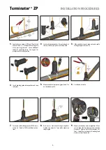
Page 3: ...d pipe and route cable through support base entry 7 Terminate cable with appropriate PETK termi nation kit Refer to PETK installation instruc tions 8 Push excess cable back through expediter Tighten cap securely Tape cable expansion loop to pipe 9 Mount junction box base on expediter Make sure to align slots to properly orient junction box base Tighten nut with Terminator LN Tool If mounting horiz...

Page 4: ... lb in See page 5 for wiring details 14 Install junction box lid and twist hand tight Insert screwdriver into ratchet slots located on side of junction box base 15 Use screwdriver to ratchet on junction box lid Lid will rotate 30 degrees 16 Lid latch mechanism fully engaged To remove lid repeat steps 14 and 15 but in the opposite direction A1 Locate bus connection HPT and FP only and cable as show...

Page 5: ...e at angle to aid in piercing grommet Leave additional cable for expansion loop B2 Insert three cables into expediter B3 Mount expediter with three cables Do not band over cable Wiring Details C2 In Line Splice and T Splice C3 End Termination 1 to 2 Heating Cables Re move jumpers for 2 cable terminations TerminatorTM ZP INSTALLATION PROCEDURES ...

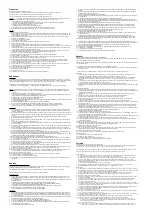
Page 6: ...ungen des Standfußes ohne dabei das Heizkabel zu kreuzen 6 Schneiden Sie das Heizkabelende waagerecht ab 7 Montieren Sie den zum Heizkabel passenden Heizkabelanschluss PETK Zur Montage beachten Sie die Montageanleitungen im Beipack 8 Schieben Sie das konfektionierte Heizkabel in den Standfuß zurück Verschrauben Sie die Kappe vorsichtig Befestigen Sie die Heizbandschlaufe mit Band auf dem Rohr 9 Pl...

Page 7: ...n Dr PO Box 609 San Marcos TX 78667 0609 USA Phone 1 512 396 5801 European Headquarters Boezemweg 25 PO Box 205 2640 AE Pijnacker The Netherlands Phone 31 0 15 36 15 370 For the Thermon office nearest you visit us at www thermon com Tel 44 0 191 490 1547 Fax 44 0 191 477 5371 Email northernsales thorneandderrick co uk Website www heattracing co uk www thorneanderrick co uk ...

Reviews: