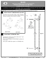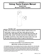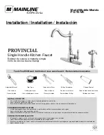
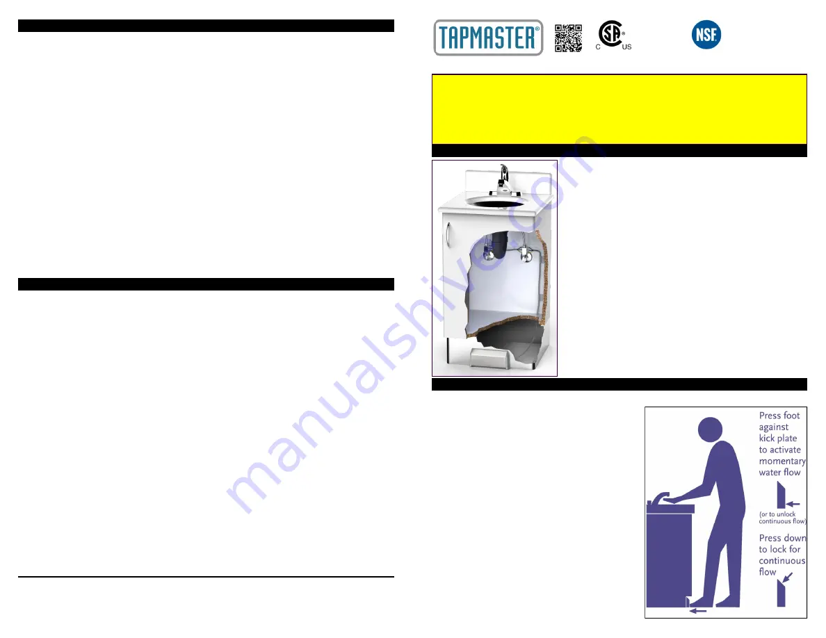
This illustration shows a typical installation for the Model 1750
Tapmaster. The valve blocks are connected in
-
line on the hot and
cold water supplies with
3/8”
compression fittings and the kick plate
is mounted on the cabinet toe kick with the control tubing routed in
between them.
The Model 1740 and 1742 come with one valve block and are
generally used on tepid or single line water supplies. The 1752 and
1742 come with two kick plates and are typically used on island
cabinets that require control from either side. Installations will vary
according to the design of the cabinet, type of faucet and plumbing
hardware. In some cases, it may be simpler to connect the valve
blocks at some convenient mid
-
point along the 3/8" supply tubing.
In this case it will be necessary to obtain a 3/8" x 3/8" compression
connector
(available at most hardware stores) to connect the inlet
fitting into the water lines. Other plumbing arrangements may be
encountered where larger than 3/8" O.D. tube sizes are used. In
these situations reducing adapters
(available at most hardware
stores) must be obtained to permit installation of the Tapmaster.
Although the Tapmaster will work with virtually any faucet, faucets
that have handles which give a visual reference for flow and
temperature are recommended. Cabinet toe kicks will also vary in
design and construction. They should allow free access to the kick
pedal, particularly the upper angled face to facilitate the latching of
the
“
continuous on
”
feature. Toe kicks of less than
4”
in height are
not recommended.
GENERAL
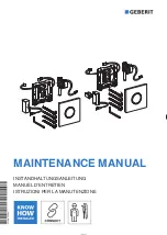
To operate Tapmaster in
momentary mode, simply press the foot lightly against the kick plate and
open the faucet to the desired flow and temperature.
By releasing the kick plate, Tapmaster shuts off the
water flow to the faucet. Once the faucet has been
adjusted it should be left open.
For
continuous mode, press down in the middle of the
kick plate angled face until it
“
latches
”.
This will
provide continuous flow to the faucet until the kick
plate is tapped again to unlatch. The latching feature
allows the operator to use the faucet for such things
as filling the sink, etc. It is not recommended for
repeated on/off operation. This feature has been
intentionally designed to require a deliberate
thoughtful motion on the part of the operator to
prevent latching inadvertently .
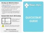
Tapmaster does not alter the appearance of the
faucet, therefore a
removable decal is provided which
may be located on nearly any hard smooth surface
near the faucet to alert people to its method of
operation. It is not recommended to be used on dry-
wall.
INSTALLATION INSTRUCTIONS: Models 1750, 1752, 1740 & 1742
TROUBLE SHOOTING
FIVE YEAR LIMITED WARRANTY
Congratulations on your purchase of TAPMASTER Hands Free Faucet Controller!
TAPMASTER products are thoroughly tested before shipment and are warranted to be free of
defects in material and workmanship for five years from the date of original purchase. The sole
obligation of Tapmaster Incorporated under the warranty is to provide replacement parts or at its
option to repair the defective product or to provide the replacement product. Replacement parts
furnished in fulfillment of this warranty are warranted only for the unused portion of the original
warranty. Labor and shipping charges are not included.
Warranty conditions
-
The five year warranty is subject to exclusions and limitations as stated
below:
Warranty extends only to defects which occur during normal use and intended applications and
does not extend to damage to products or parts resulting from alteration, repair, modification or
faulty installation. This warranty does not cover damage resulting from water borne debris or
from media other than clean potable water. Tapmaster Incorporated makes no other express
warranty on this product, all implied warranties including any implied warranty of merchantability
and fitness for a particular purpose are hereby disclaimed and excluded. In no event shall Tap-
master Incorporated be liable for special, incidental or consequential damages resulting from the
use of this product or arising from breach of warranty or contract, negligence, loss of time,
inconvenience or loss of use of equipment.
Rev 3.0
-
4
-
PH: 800
-
791
-
8117
FAX: 403
-
275
-
5928
Web: www.tapmaster.ca
E
-
mail: info@tapmaster.ca
Tapmaster Incorporated
3
-
1470 28th Street NE
Calgary, AB Canada
T2A 7W6
Symptom
Possible Cause
Remedy
The hot or cold water is very
slow to turn on
Pinched tubing
Check control tubing (yellow
and blue lines)
The hot or cold water is very
slow to shutoff or will not
shutoff
Pinched tubing
Check control tubing (green
and blue)
Noise from the Valve Blocks
while the water is running
The Valve Block may have
excessive debris trapped
under the Filter
-
screen
Service the Valve Blocks
Noise from the Valve Blocks
when turning water on and
off
Air in the system
Operate the pedal on and off
rapidly to clear air from the
valves.
For further information: www.tapmaster.ca or call 800
-
791
-
8117
OPERATION
PATENT NUMBERS
U.S. 5,505,227, 6,254,057,
6,382,585
Canadian 2,109,684
European 0654628
International & Other Patents
Pending
CSA
-
B125.1
-
18
ASME A112.18.1
-
2018
NFS/ANSI 61
-
2016
NSF/ANSI 372
-
2016
LOW LEAD CONTENT
DRINKING WATER
CAUTION
-
READ BEFORE INSTALLATION
Tapmaster Incorporated will not be held liable for damage to property or persons resulting from improper installation of this product
.
If you are uncertain about
any part of the installation process, please contact us for assistance or consult a professional tradesperson before installation.
•
Water lines must be flushed prior to installation
•
Do not install if control tubes are damaged in any way
•
Control tubes are pressurized after installation. Do not
expose tubing to excessive heat, unsealed chemicals, or
physical damage
•
Use of substitute tubing voids manufacturer warranty and
liability
•
Do not expose valves to thread sealants/plumbers putty
•
Operating Range: 0
-
125 psi (8.6 bar) Max, 140° F
(60° C) Max