background image

1

M-2600

MK

II


QUICK TIPS

M-2600

MK

II Application Guide Introductory Briefing

The M-2600

MK

II Series mixing console offers tremendous signal routing flexibility

combined with a versatile and musical equalization system.  This guide is designed to
assist you in maximizing your use of the mixer.  To gain the most from this guide, configure
your system as outlined on pages 3 and 4.

Taking Advantage of the M-2600

MK

II’s Split EQ Capability

The M-2600

MK

II Series Consoles provide four band, splittable EQ on each channel strip.

HI and LOW EQ are of the shelving variety while HI MID and LO MID EQ is sweepable.

Both types of equalization default to the Channel Path.

Beneath the HI and LOW EQ is a switch labeled MONitor.  Pressing this switch places the

HI and LOW EQ in the monitor path.  Beneath the HI MID and LO MID EQ there is another

switch labeled MONitor.  Pressing this switch places the HI MID and LO MID EQ in the

monitor path.

Beneath the HI MID / LO MID EQ MON switch is another switch labeled EQ.  This switch

inserts or removes the two types of equalization from the Channel Path only.  Its function

is dependent upon the setting of the two MONitor switches.

By taking advantage of the MONitor switches found in the EQ section of the M-2600

MK

II

consoles, you have the advantage of using the EQ in any combination that best suits your

needs.  As this level of flexibility provides countless opportunities to fine tune your mix, we

encourage you to experiment with this section of the console.  The following example is

only one of many possible uses for splittable EQ.

You're mixing down eight tracks from tape with a number of virtual tracks via your MIDI

system.  The tape recorder is feeding TAPE IN, channels 1 through 8, which are now

placed in the Channel Path via the FLIP switches.  As your MIDI system is huge, you are

also using channel inputs 1 through 8 (LINE engaged) to accommodate the individual

outputs of your drum machine.  These signals are now in the Monitor path.  Channel

one of the console is managing both the brass parts on tape (Channel Path) and the

kick drum (Monitor Path) via the MIDI system.

You want to boost the low end punch of the kick drum.  Press the upper MONitor switch in

the EQ section.  You can now adjust the LOW EQ control and affect a change to the kick

drum.

By pressing the EQ button in the HI MID / LO MID area of the EQ section, you can now

experiment with the sweepable EQ to obtain the greatest clarity from your brass parts

which are in the Channel Path - ensuring this track has the bite that it needs to cut through

the mix.

Summary of Contents for M-2600MKII

Page 1: ...of the MONitor switches found in the EQ section of the M 2600MKII consoles you have the advantage of using the EQ in any combination that best suits your needs As this level of flexibility provides c...

Page 2: ...MIC LINE inputs to now feed the MONitor LEVEL control while the TAPE IN jack now feeds the Channel Fader Channel Monitor Path Explanation with the M 2600MKII To easily understand the relationship bet...

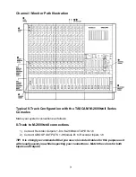
Page 3: ...ows 8 Track to M 2600MKII connections 1 Connect Recorder Outputs 1 8 to M 2600MKII TAPE IN 1 8 2 Connect GROUP OUTPUTS 1 8 Module 1 to Recorder Inputs 1 8 TIP It is strongly recommended that you use c...

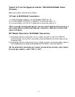
Page 4: ...recorder connect the L R outputs of the mastering deck to either the M 2600MKII s 2TR INPUT or the EXT INPUTS TIP Be advised that monitoring your master recorder will be a function of the Control Roo...

Page 5: ...e as it will visually assist you while inspecting your connections Match the colors for both Inputs and Outputs DAT Master Recorder to M 2600MKII Connections 1 Depending upon the connections on your m...

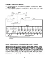
Page 6: ...Direct Outputs for each 8 channel module For example the M 2600MKII 24 has 24 channels or three 8 channel modules Each of these three modules incorporates a set of 8 Group Direct Outputs and each set...

Page 7: ...he rear of this guide and then perform the following 1 Place track one on your recorder into RECORD READY status 2 Feed signal to the Channel 1 LINE input making certain the LINE switch at the top of...

Page 8: ...may currently be in use for the purpose of creating a Cue Mix this example will use AUX 5 for the effects loop Proceed as follows 1 Patch in the reverb unit via AUX SEND and RETURN 5 set the reverb s...

Page 9: ...ld use a single delay unit on AUX 6 8 When connecting your effects loop you can send to the processor from either AUX SEND 5 or 7 when they are summed When summing these effects sends it is advisable...

Page 10: ...r Uses the Monitor Section for his Mix 1 Set Pan and Level for all signals returning via TAPE IN 2 Control Room Assign will normally be set to STEREO 3 Control Room Level and L R Stereo Master fader m...

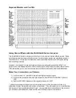
Page 11: ...using these as stereo effect sends This will enable you to use two discreet stereo effects processors with the M 2600MKII Make Your Connections as Follows 1 Connect AUX 1 L and 2 R to the left and rig...

Page 12: ...ng the M 2600MKII Zeroing the mixer is frequently performed at the start of a new project as a cautionary measure to ensure the engineer that the signal being monitored is flat as opposed to the inclu...

Reviews: