background image

TASK FORCE TIPS, Inc.

2800 E. Evans Ave., Valparaiso, IN 46383-6940 USA

800-348-2686 • 219-462-6161 • Fax 219-464-7155

INSTRUCTIONS FOR INSTALLATION, SAFE OPERATION AND MAINTENANCE

MANUAL: Remote Control

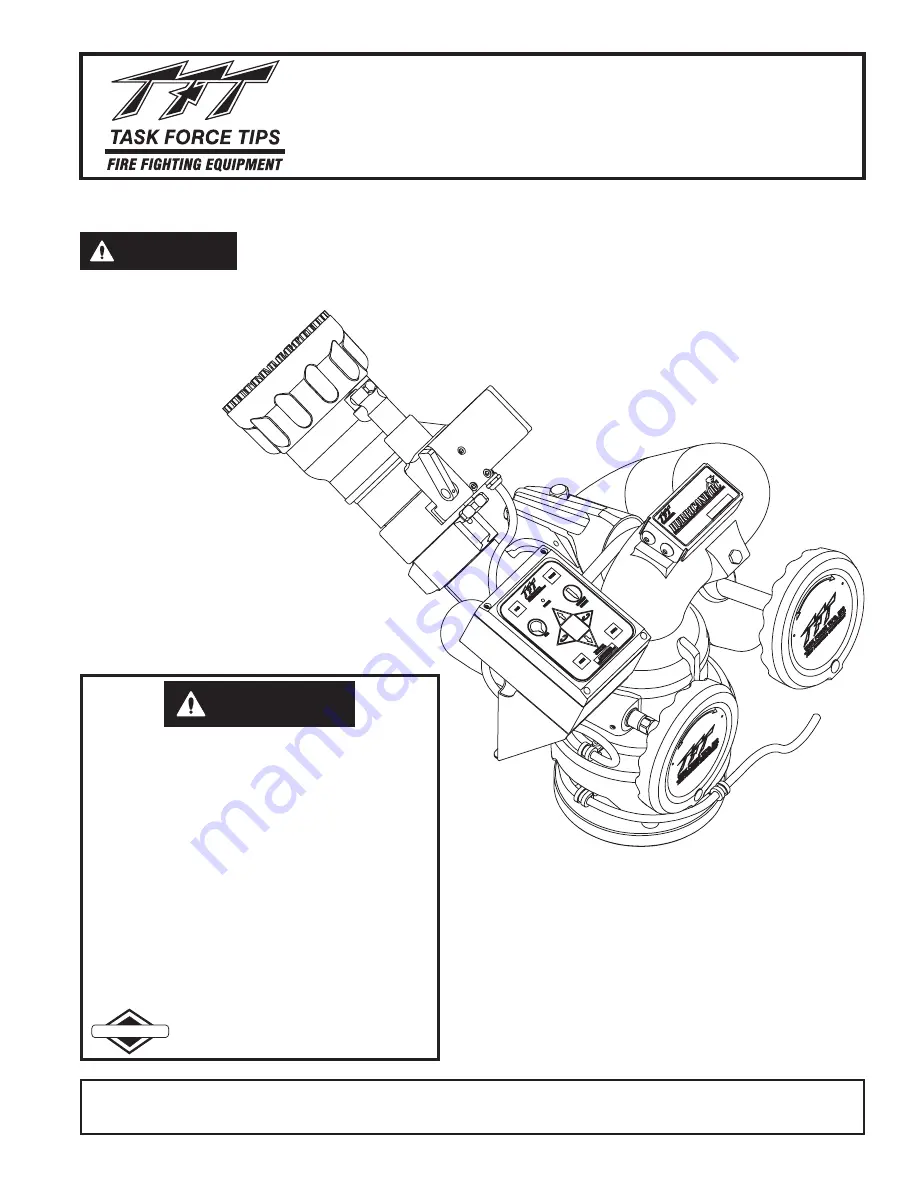
HURRICANE RC MONITOR

Read instruction manual before use. Operation of this device without understanding the manual
and receiving proper training is a misuse of this equipment. A person who has not read and
understood all operating and safety instructions is not qualified to operate the Hurricane RC
monitor.

DANGER

This instruction manual is intended to familiarize installers,
firefighters and maintenance personnel with the installation,
operation, servicing, and safety procedures associated with
the Hurricane RC Monitor.

This manual should be kept available to all operating and
maintenance personnel.

Model XFIH-E11A Monitor

Shown With

Model M-ERP-NJ Nozzle

Maximum recommended inlet
pressure is 200 psi. (14 bar)

MADE IN USA • www.tft.com

©Copyright Task Force Tips, Inc. 2004-2006

LIX-300 January 24, 2006 Rev05

®

The member companies of FEMSA that provide emergency response equipment
and services want responders to know and understand the following:

1. Firefighting and Emergency Response are inherently dangerous activities

requiring proper training in their hazards and the use of extreme caution at all
times.

2. It is your responsibility to read and understand any user’s instructions provided

with any piece of equipment you may be called upon to use.

3. It is your responsibility to know that you have been properly trained in

Firefighting and /or Emergency Response and in the use, precautions, and
care of any equipment you may be called upon to use.

4. It is your responsibility to be in proper physical condition and to maintain the

personal skill level required to operate any equipment you may be called upon
to use.

5. It is your responsibility to know that your equipment is in operable condition and

has been maintained in accordance with the manufacturer’s instructions.

6. Failure to follow these guidelines may result in death, burns or other severe

injury.

DANGER

PERSONAL RESPONSIBILITY CODE

Fire and Emergency Manufacturers and Services Association, Inc.

P.O. Box 147, Lynnfield, MA 01940 • www.FEMSA.org

FEMSA

Summary of Contents for HURRICANE RC XFIH-E1 A Series

Page 1: ...6 LIX 300 January 24 2006 Rev05 The member companies of FEMSAthat provide emergency response equipment andserviceswantresponderstoknowandunderstandthefollowing 1 Firefighting and Emergency Response are inherently dangerous activities requiring proper training in their hazards and the use of extreme caution at all times 2 Itisyourresponsibilitytoreadandunderstandanyuser sinstructionsprovided withan...

Page 2: ...DIRECTLY TO PROTECTED POWER SUPPLY 19 5 9 1 ELECTRICAL WIRING 5 10 OPERATOR STATION INSTALLATION DIRECTLY TO MONITOR 20 5 11 HURRICANE RC AERIAL TRUCK INSTALLATION 20 21 5 11 1 ELECTRONICS ENCLOSURE MOUNTING 5 11 2 ELECTRICAL WIRING 5 11 2 1 LADDER INSTALLATION ELECTRICAL WIRING 5 11 2 2 PLATFORM INSTALLATION ELECTRICAL WIRING 5 12 6 1 MANUAL OVERRIDE HANDWHEELS 22 6 2 ELECTRICAL MODEL 22 24 6 2 1...

Page 3: ...angeable horizontal rotation stops at 45 90 and 135 either side of center position Elevation range is 90 above horizontal and 45 below Designed for field changeable 12 or 24 VDC operation The Hurricane RC comes with a factory installed control panel mounted on the monitor for controlling horizontal rotation elevation and nozzle pattern See Task Force Tips Price List and Product Specifications for ...

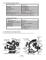
Page 4: ...rizontal rotation motor 6 amps 10 amps Nozzle motor 1 amp 5 amps with rated water pressure applied At rest current 25 amps Recommended fuse or circuit breaker size 15 amps 12 volts 7 5 amps 24 volts Operating temperature range 30 F to 120 F 34 C to 49 C Environmental Rating All components designed to meet minimum rating of NEMA 4 IP65 3 2 PART IDENTIFICATION AND MODELS The Hurricane RC Monitor as ...

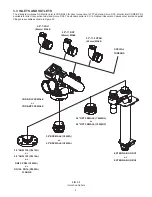
Page 5: ...le Various other inlet and oputlet fittings are available as shown in Figure 3 3 5 FIG 3 3 Inlets And Outlets 2 5 7 5 NH 65mm MALE 2 5 11 BSP 65mm MALE 2 5 11 5 NPSH 65mm MALE SPECIAL THREADS CODE RLF FEMALE or CODE RPF FEMALE 3 0 NPT FEMALE Y4440NL or 4 0 NPT FEMALE Y4450NP EXTEND A GUN RC3 or EXTEND A GUN RC4 3 0 ANSI 150 Y4410A or 4 0 ANSI 150 Y4415A or DN80 PN16 Y4423A or DN100 PN16 Y4425A FLA...

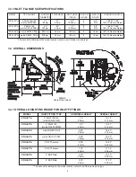
Page 6: ... and type 18 64 473MM 15 43 392MM 7 90 201MM 10 74 273MM 5 89 150MM 3 64 93MM SHOWN WITHOUT INLET FITTING SEE TABLE IN SECT 3 4 1 FOR ADDITIONAL HEIGHTS VERT ICAL R A N G E O F M O T I O N A B O V E 4 5 D E G B E L O W 9 0 D E G 3 3 1 INLET FLANGE SIZE SPECIFICATIONS MODEL FITS FLANGE OUTSIDE THICKNESS BOLT HOLE HOLES BOLTS XFIH E1 A 3 ANSI 125 150 7 5 75 6 0 4 5 8 76 80 FT LBF metric DN8 PN20 190...

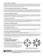
Page 7: ...buttons the associated motor starts in slow speed mode so that the operator can accurately control the water stream After approximately 1 2 seconds the motor automatically ramps up to a fast speed for quickly moving into position When quickly changing directions monitor retains speed from prior move If low speed is selected monitor does not ramp to high speed but remains in slow speed 3 5 5 COMMUN...

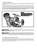
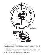
Page 8: ...holes will give desired direction relative to the Straight Back Reference Mark when the monitor is installed 2 Screw monitor onto inlet adapter or Extend A Gun RC until threaded joint bottoms out Do not use pipe dope or Loctite on the inlet base threads These threads are sealed with an o ring The use of thread locking compounds will make removal difficult 3 Unscrew monitor slightly until a pair of...

Page 9: ...X 33 IN 1 1 2 TURNS APPROX 37 IN The Extend A Gun manual override knob may be mounted in any of four possible orientations 90 degrees apart relative to the Straight Ahead Reference Mark on the monitor NOTE Hurricane RC monitor for use with Extend A Gun RC comes with the wire installed in a nylon tube The nylon tubing gives the wire additional stiffness so it better follows as the Extend A Gun RC e...

Page 10: ...ds on the Hurricane RC in both size and type Mismatched or damaged threads may cause the nozzle to leak or uncouple under pressure and could cause injury CAUTION Do not connect aluminum to brass or brass to aluminum Dissimilar metals coupled together can cause galvanic corrosion that will freeze the threaded joint or cause complete loss of thread engagement If dissimilar metals must be coupled tog...

Page 11: ...e RC installed from factory that will empty the water from the low point of the lower bend to prevent freezing Figure 3 2 This valve will close automatically when the internal pressure in the monitor reaches approximately 5 psi 0 34 bar and will reopen again when the pressure drops to this point Refer to Section 6 4 for disabling the automatic drain if desired Asecondary drain valve should be inst...

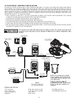
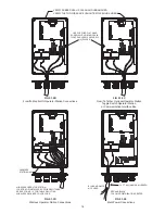
Page 12: ...lose to control box with plastic wire ties or cable clamps to relieve stress on the cables Disconnect power before installing or servicing the electrical components The RC monitor control boxes and motors are not rated as ignition proof explosion proof or intrinsically safe The electric motors and other components are ignition sources The electric drives should be operated only in areas where ther...

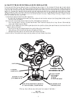
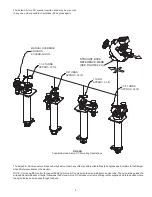
Page 13: ...ION and discard Refer to Figure 5 1 2D for connections Refer to Figure 5 1 2 for wire color designations OPERATOR OPERATOR MAIN POWER CONNECTION TO TRUCK Route cable and connect to a protected circuit from the truck s power distribution center Connect the red wire to positive and the black wire to negative ground Refer to Figure 5 1 2E for connections IMPORTANT When mechanical installation and ele...

Page 14: ...ARE CAUGHT BETWEEN LID AND BOX USE SUPPLIED FLAT HEAD SCREWS WITH O RING SEALS TIGHTEN SCREWS SECURELY 6 PLACES FIG 5 1 2D Wireless Operator Station Connections WIRELESS STATION ONLY WIRELESS OPERATOR STATION JOYSTICK OR INSTALLER SUPPLIED SWITCHES SEE SECTION 5 1 2 FOR TABLE DEPICTING WIRELESS RECEIVER COLOR CODE FIG 5 1 2E Main Power Connections BLUE AND WHITE NOT USED RED AND BLACK TO POWER DIS...

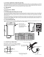
Page 15: ...rews Make sure the area on the back side of the mounting surface is clear of obstructions We recommend a minimum thickness of 3 32 093 2 4 mm in aluminum and 5 64 078 2mm in steel See the chart in Figure 5 3 1 to determine the correct pilot hole size 5 3 1 HOLSTER MOUNTING Select proper location for mounting holster preferably inside a storage compartment Panel space required will be 6 5 x 8 0 165...

Page 16: ... The optimal operating range is 500 150 m Check the operating range after mounting receiver If range is inadequate the receiver may need to be remounted in a more exposed area Fig 5 4 1 Wireless Receiver Hole Dimensions DEUTSCH CONNECTOR PLUG DRILL 2 PILOT HOLES refer to hole size chart MOUNT HOLSTER WITH 2 1 4 20 SELF TAPPING SCREWS TIGHTEN SECURELY Material Use Material Use Thickness Drill Thick...

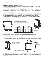
Page 17: ... COMM Communication Interface Box or a separately supplied Y4E RP Primary Operator Station By connecting the joystick to a communication interface box a primary operator station is not required and the installer has the option to enable the joystick operator station with the master override feature see Section 6 2 2 When a pump panel operator station is being installed the installer can connect th...

Page 18: ...5 6 1 for mounting hole dimensions 4 45 113 mm 2 05 52 mm Figure 5 6 1 Toggle Switch Operator Station Hole Dimensions 5 6 2 ELECTRICAL WIRING See section 5 1 2C if connecting to a Primary Operator Station See section 5 10 if connecting directly to monitor MOUNT ENCLOSURE WITH 2 1 4 20 FASTENERS TIGHTEN SECURELY WATER VALVE CONNECTION TRIGGER ACTUATION SWITCHES ORANGE WIRE TO GROUND 5 AMP SWITCH CO...

Page 19: ...E JUMPER UP DOWN LEFT RIGHT FOG STREAM SPEED STOW WHITE BLUE YELLOW BROWN GREEN ORANGE BLACK RED Function Interface Box Cable Color Figure 5 7 2 Communication Interface Wire Color Function 5 8 2 ELECTRICAL WIRING The monitor position display needs to be connected to 12 24VDC red and ground black The blue white wires from the position display cable need to be connected to the blue white wires from ...

Page 20: ...e will remain at an acceptable level during monitor operation 5 10 OPERATOR STATION INSTALLED DIRECTLY ON MONITOR Recommended Cable Gauge Max Length Gauge 40 ft 14AWG 65 ft 12AWG 80 ft 2 14AWG 105 ft 10AWG 130 ft 2 12AWG The electric RC monitor can be directly connected to a protected power supply see section 5 9 and then be controlled by one of the following without the use of aY4E RP primary ope...

Page 21: ... joystick toggle switches relay contacts or Canbus output module The electronic interface accepts 12 24 VDC signals but can be field changed to accept ground signals The electronics enclosure is configured so that signals connected to the PRIMARY CONTROLcable will override any other operator stations see section 6 2 1 See Figure 5 11 2 2 for wiring connections Figure 5 11 2 2 Electrical Components...

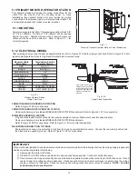
Page 22: ...ing the red button at the bottom will deactivate the transmitter The transmitter will automatically deactivate after 10 minutes if no buttons are pressed 6 2 1 6 JOYSTICK OPERATOR STATION This operator station is installed in a protected location and allows the monitor to be controlled by a joystick The electric Hurricane RC monitor has seven different styles of operator stations for use in variou...

Page 23: ...OVE TO STOW POSITION and and and and 6 2 3 2 STOW PROGRAMMING EXAMPLE Press hold STOW button until LED blinks Press release UPbutton monitor will move until hard stop reached LED blinks rapidly Press release RIGHTbutton monitor will move until hard stop reached LED blinks rapidly Press LEFTbutton to move 45 degrees Press release STOW button LED blinks rapidly Press DOWN button to move 90 degrees P...

Page 24: ...D will continue to blink in program mode Move monitor to 2nd point press OSC button LED will blink rapidly to acknowledge position Repeat until pattern is complete Press hold OSC button until LED turns off NOTE PATTERN WILL BE CLEARED UPON POWER LOSS TO OSCILLATE Pattern must be programmed first Press release OSC button TO STOW Press release STOW button Programmable refer to manual Y5705 800 348 2...

Page 25: ...sembly 6 3 RECOMMENDED MONITOR STOWING POSITION For truck mounted applications it is recommended that the monitor be stowed in a position such that the monitor s nozzle rests against a bracket or support surface This will minimize bouncing of the nozzle when the apparatus is traveling On many vehicle installations the monitor is the highest point on the apparatus Often it is critical that the moni...

Page 26: ...0 210 600 280 670 350 1 75 580 190 700 290 810 380 910 480 2 00 750 250 920 380 1060 500 1190 630 Nozzle Pressure PSI Nozzle 40 60 80 100 Diameter Flow Reaction Flow Reaction Flow Reaction Flow Reaction inches GPM lbf GPM lbf GPM lbf GPM lbf 35 1360 50 1670 80 1890 110 2120 140 38 1590 60 1970 100 2270 130 2540 160 45 2200 90 2650 130 3070 170 3440 220 50 2840 110 3480 170 4010 230 4500 290 Nozzle...

Page 27: ...DISTANCE FEET VERTICAL DISTANCE FEET VERTICAL DISTANCE M 0 0 40 0 80 0 20 0 60 0 HORIZONTAL DISTANCE M 1 375 INCH TIP 0 10 20 0 20 40 60 80 0 0 40 0 80 0 120 0 160 0 200 0 240 0 280 0 40 PSI 60 PSI 100 PSI 80 PSI HORIZONTAL DISTANCE FEET VERTICAL DISTANCE FEET VERTICAL DISTANCE M 0 0 40 0 80 0 20 0 60 0 HORIZONTAL DISTANCE M 1 75 INCH TIP 0 10 20 0 20 40 60 80 0 0 40 0 80 0 120 0 160 0 200 0 240 0...

Page 28: ...ach 0 40 80 120 160 200 240 280 320 0 20 40 60 80 100 120 140 160 VERTICAL DISTANCE FEET HORIZONTAL DISTANCE FEET 80 20 40 60 0 20 40 0 HORIZONTAL DISTANCE METERS VERTICAL DISTANCE METERS 2 0 INCH TIP 100 PSI 1190 GPM 60 DEGREES 30 DEGREES 45 DEGREES 75 DEGREES 0 10 40 20 80 0 40 80 120 160 200 240 280 320 360 HORIZONTAL DISTANCE FEET 2 00 INCH TIP 100 PSI 1190 GPM VERTICAL DISTANCE FEET NO WIND 2...

Page 29: ... STREAM STRAIGHTENERS 6 5 3 HURRICANE RC MONITOR FRICTION LOSS The friction loss of the Hurricane RC Monitor is shown below in Fig 6 5 3 FIG 6 5 3 Hurricane Monitor Friction Loss 0 0 5 0 10 0 15 0 20 0 25 0 30 0 0 0 200 1000 2000 3000 400 4000 5000 600 800 1000 1200 1400 0 0 5 1 5 1 0 2 0 FLOW GPM FLOW L min PRESSURE LOSS BAR PRESSURE LOSS PSI 6 5 2 AUTOMATIC NOZZLES Automatic nozzles maintain a c...

Page 30: ...rogram enable timer expired REMEDY Clean out debris or replace damaged parts Clean out debris or replace damaged parts Grease see section 8 1 Clean out debris or replace damaged parts Grease see section 8 1 Check wiring and reverse polarity Check connections and wiring per section 5 1 2 Check blue white communication wiring Verify code versions on monitor and all operator stations Check axis motor...

Page 31: ...e Hurricane RC monitor after repairs are made or any time a problem is reported to verify operation in accordance with Task Force Tips test procedures Consult the factory for the test procedure that corresponds to the model and serial number of your monitor Any equipment that fails the test criteria should be removed from service immediately Equipment can be returned to the factory for service and...

Page 32: ...SSEMBLY 9 0 EXPLODED VIEW DRAWINGS AND PARTS LIST 2 4 1 3 6 7 8 9 11 10 12 13 14 15 20 18 19 25 26 27 28 29 30 33 31 32 28 34 35 18 40 41 42 36 37 38 39 2 3 4 16 13 12 6 5 21 23 22 24 43 44 13 24 49 48 46 47 45 50 48 24 17 52 51 51 ...

Page 33: ... RING 350 1 VO 350 26 BALL 5 16 TORLON 49 98 VB 312TO 27 BASE CODE RLF 3 ALUM 1 Y4405A 28 FLAT WASHER 1 4 3 VW687X281 50 29 1 4 28 x 1 2 BHCS 2 VT25Y28BH504 30 O RING 236 1 VO 236 31 DRAIN HOUSING 1 X375 32 DRAIN VALVE 1 X382 33 1 4 20 x 1 2 BHCS 1 VT25 20BH500 34 O RING 130 1 VO 130 35 1 4 28 x 3 8 SHCS CUP PT 2 VT25 28SS375 36 HEADED BUSHING 1 Y4141 37 SPACER 1 Y4150 38 SPACER WASHER 1 VW97X595 ...

Page 34: ...ION QTY PART ROLLER CHAIN RING SPROCKET SLAVE SPROCKET DRIVE BUSHING MOTOR COVER 1 4 28 x 1 2 BHCS 1 6 32 x 5 16 LONG SHCS WITH HEAD SEAL 4 VT06S32SH312 2 CUP SEAL 1 0625 x 5625 x 1 4 1 Y4620 3 MOTOR SOCKET 1 Y4615 4 1 5 1 6 1 7 1 8 1 9 1 DESCRIPTION QTY PART O RING 018 VO 018 CONDUIT FITTING Y5213 HOSE 3 8 ID PUSH LOK Y5250 O RING 038 VO 038 GEAR MOTOR WITH ENCODER Y4610 ENCLOSURE Y4616 3 6 7 9 1...

Page 35: ...Y5700 9 BOARD MOTOR CONTROL 3 Y5100 10 BOARD MAIN 1 Y5105 11 V10 32 x 1 4 SET SCREW 1 VT10Y32SS250 12 O RING 018 2 VO 018 13 CONDUIT HOSE FITTING 2 Y5213 14 FEMALE PLUG 2 POLE FOR HURRICANE RC NOZZLE CONNECTION 10 0 TOTAL 5 0 EXPOSED CABLE Y5280 LENGTH USED NOT INCLUDING PLUG 9 4 MONITOR CONTROL BOX ASSEMBLY TO POWER CABLE TO TFT ER NOZZLE MALE PLUG TO HORIZONTAL GEAR MOTOR TO VERTICAL GEAR MOTOR ...

Page 36: ...iens and encumbrances This is a limited warranty The original purchaser of the equipment any person to whom it is transferred and any person who is an intended or unintended beneficiary of the equipment shall not be entitled to recover from TFT any consequential or incidental damages for injury to person and or property resulting from any defective equipment manufactured or assembled by TFT It is ...

Reviews: