background image

Cosmo

installation guide

March 2017

Summary of Contents for Cosmo

Page 1: ...Cosmo installation guide March 2017...
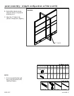
Page 2: ...nnection to door 33 stackable frame connection to door with stackable panel frame 34 door assembly straight configuration 36 door assembly 90 T cross 120 135 and straight configuration 38 door with st...

Page 3: ...tion 82 top panel shared shelf installation 83 Accessories 85 93 accessory bar installation 85 accessory organizer installation 87 whiteboard marker brush tray installation 89 top mounted screen insta...

Page 4: ......

Page 5: ...ary Site Preparation 1 Clear all obstacles that could interfere with the installation process 2 When doing a reconfiguration ensure that all furniture to be re used are clear of computers accessories...

Page 6: ...al cleaner such as Cabinet or Countertop both manufactured by Magic American Corporation Acrylic Dust regularly to keep surfaces free of dust particles Clean any dirt with a damp cloth Dry the area us...

Page 7: ...s same height panels Note Cosmopolitan offers the flexibilty of 90 180 120 and 135 degree connections at varying heights Illustrated below are a few connection possibilities for Cosmopolitan panel fra...

Page 8: ...8548S 8548S WALL WALL CONNECTOR 12 0 MAX 12 0 MAX 2 0 MIN 2 0 MIN 2 0 MIN 8548S 8524S 8548S 8548S WALL WALL CONNECTOR When specifying Cosmopolitan it is important to be mindful of the width that the p...

Page 9: ...STEP 1 1 Remove all the tiles on one side of each panel 2 Install panel electrics 3 Re install tiles previously removed install raceways STEP 2 STEP 3 installation sequence MARCH 2017 cosmopolitan 9...

Page 10: ...nel trims top caps and fillers 5 Install surface supports 6 Install overhead storage units Attach task lights to underside of overhead storage units STEP 5 STEP 6 installation sequence cont d MARCH 20...

Page 11: ...TEP 7 7 Install surfaces and keyboard trays 8 Install under desk storage units 9 Install accessory bars accessories and CPU holders STEP 8 STEP 9 installation sequence cont d MARCH 2017 cosmopolitan 1...

Page 12: ...1 2 Level off panels use the torpedo level by adjusting the glides Figure 2 3 Remove the tiles on one side of the panel Figure 3 FIGURE 1 FIGURE 2 FIGURE 3 panel assembly straight configuration GLIDE...

Page 13: ...nstall next to it NOTE Do not re install the tiles right away might need them off to install next frames FIGURE 4 TOP VIEW torpedo level drill 6 hex key tools needed box wrench hardware needed panel h...

Page 14: ...Line up two panels Figure 1 2 Level off panels use the torpedo level by adjusting the glides Figure 2 FIGURE 1 FIGURE 2 panel assembly straight configuration w filler GLIDE MARCH 2017 cosmopolitan 14...

Page 15: ...g a 6 inch hex key install the 25 mm or 1 inch hex screws into the inside edge of the panel frame this will protrude into the STRAIGHT CONNECTORS Figure 3 FIGURE 3 TOP VIEW panel assembly straight con...

Page 16: ...level drill 6 hex key tools needed box wrench hardware needed panel height inches 37 45 53 61 69 77 85 straight connector 2X 3X 3X 3X 3X 3X 4X 25mm hex screw 8X 12X 12X 12X 12X 12X 18X panel assembly...

Page 17: ...1 Line up two panels Figure 1 2 Level off panels use the torpedo level by adjusting the glides Figure 2 FIGURE 1 FIGURE 2 GLIDE MARCH 2017 cosmopolitan 17...

Page 18: ...gure 3 7 Re install the tiles previously removed if there is no panel to install next to it NOTES Do not re install the tiles right away might need them off to install next frames Sponge to be inserte...

Page 19: ...1 Line up two panels Figure 1 2 Level off panels use the torpedo level by adjusting the glides Figure 2 panel assembly T configuration FIGURE 1 FIGURE 2 GLIDE MARCH 2017 cosmopolitan 19...

Page 20: ...ot protrude through Figure 3 8 Re install the tiles previously removed if there is no panel to install next to it FIGURE 3 TOP VIEW torpedo level drill 6 hex key tools needed box wrench hardware neede...

Page 21: ...1 Line up two panels Figure 1 2 Level off panels use the torpedo level by adjusting the glides Figure 2 panel assembly cross configuration FIGURE 1 FIGURE 2 GLIDE MARCH 2017 cosmopolitan 21...

Page 22: ...rude through Figure 3 8 Re install the tiles previously removed if there is no panel to install next to it FIGURE 3 TOP VIEW torpedo level drill 6 hex key tools needed box wrench hardware needed panel...

Page 23: ...1 Line up two panels Figure 1 2 Level off panels use the torpedo level by adjusting the glides Figure 2 FIGURE 1 FIGURE 2 GLIDE MARCH 2017 cosmopolitan 23...

Page 24: ...that light will not protrude through Figure 3 8 Re install the tiles previously removed if there is no panel to install next to it FIGURE 3 TOP VIEW torpedo level drill 6 hex key tools needed box wre...

Page 25: ...1 Line up two panels Figure 1 2 Level off panels use the torpedo level by adjusting the glides Figure 2 FIGURE 1 FIGURE 2 GLIDE MARCH 2017 cosmopolitan 25...

Page 26: ...Figure 3 7 Re install the tiles previously removed if there is no panel to install next to it FIGURE 3 TOP VIEW torpedo level drill 6 hex key tools needed box wrench hardware needed panel height inch...

Page 27: ...1 Line up two panels Figure 1 2 Level off panels use the torpedo level by adjusting glides Figure 2 FIGURE 1 FIGURE 2 GLIDE MARCH 2017 cosmopolitan 27...

Page 28: ...Figure 3 7 Re install the tiles previously removed if there is no panel to install next to it FIGURE 3 TOP VIEW torpedo level drill 6 hex key tools needed box wrench hardware needed panel height inch...

Page 29: ...hat has to be raised Figure 1 2 Fasten the stackable frame panel extrusions by the base frame of the panel with a 25 mm or 1 inch hex screw on each side The screws have to be inserted into the holes p...

Page 30: ...l frame in the holes provided The U brackets will hold the tiles that have to be inserted to the stackable frame Figure 3 4 Complete the installation by inserting removed panel tiles and trims at thei...

Page 31: ...ch hex screw The screws have to be inserted into the holes provided from the inside of the panel frame use a 6 inches hex key to tighten FIGURE 1 STACKABLE PANEL stackable frame connection to stackabl...

Page 32: ...ot re install the tiles right away might need them off to install next frames TOP VIEW torpedo level drill 6 hex key tools needed box wrench hardware needed stackable panel height 8 16 24 inches 25mm...

Page 33: ...e panel extrusions by the base frame of the panel with a 25 mm or 1 inch hex screw on each side The screws have to be inserted into the holes provided from the inside of the panel frame use a 6 inches...

Page 34: ...o be inserted into the holes provided from the inside of the panel frame use a 6 inches hex key to tighten FIGURE 1 stackable frame connection to door with stackable panel frame STACKABLE DOOR PANEL S...

Page 35: ...rench 1 lock set tools hardware needed stackable frame connection to door with stackable panel frame cont d 25mm HEX SCREW DOOR FRAME STACKABLE PANEL FRAME STACKABLE PANEL FRAME hardware needed stacka...

Page 36: ...eft or to the right 4 Using a 2 Robertson long bit insert the 1 1 2 inches tapping screws into the holes on the edge of the panel frame which will then protrude into the door frame Figure 2 5 Step on...

Page 37: ...tall the tile previously removed TOP VIEW FIGURE 3 drill torpedo level 2 Robertson long bit 16 1 1 2 self tapping screw box wrench 1 lock set tools hardware needed door assembly straight configuration...

Page 38: ...nels either to the left or to the right 3 Using a 6 inches hex key insert the 25 mm or 1 inch hex screws into the holes on the edge of the frame from the inside the screws will protrude into the conne...

Page 39: ...with the lock set Figure 4 6 Re install all the tiles previously removed drill torpedo level box wrench tools hardware needed 6 hex key 8 25mm hex screw connectors T cross FIGURE 4 LEVER LOCKSET 1 lo...

Page 40: ...table wall connector 6 Remove wall connector then drill wall through the markings Insert wall anchors 7 Place the adjustable wall connector back onto the wall line up the holes on both wall and connec...

Page 41: ...inch oval head screws with 2 Robertson bit Figure 3 10 Attach the door with stackable frame to panel frame refer to the installation guide stackable frame connection to door with stackable panel frame...

Page 42: ...e where the sliding door is going to be installed Figure 2 3 Position the vertical post at the edge of the frame and screw it to the frame with six 1 inch self tapping screws Figure 3 Figure 4 shows w...

Page 43: ...assembled trim on top of the frame Figure 5 5 Install all tiles on the frame where the sliding door is being installed Figure 6 6 Place the sliding door into the bottom bracket of the vertical post F...

Page 44: ...of sliding door Figure 9 The bumper and screws are on the same side of the frame door Door side with bumper and screws to be installed inside the office sliding door installation cont d FIGURE 9 TOP B...

Page 45: ...onnector then drill wall through the markings Insert wall anchors 7 Place the adjustable wall connector back onto the wall line up the holes on both wall and connector then place the 10 screws provide...

Page 46: ...the frame square tubing configuration into the adjustable wall connector according to the gap between frame and wall Tighten frame square tubing with wall connector on both sides using 11 16 inch ova...

Page 47: ...el trim and filler installation FIGURE 1 top trim installation panel to wall adjustable connection FIGURE 2 tools hardware needed measuring tape hacksaw CUT OFF EXCESS TRIM NEW SIZE TOP TRIM TOP TRIM...

Page 48: ...ws provided through holes and tighten using 2 Robertson bit 4 Re install the tiles previously removed FIGURE 1 NOTES Illustrations show anchorage to dry wall Only E Z anchors are suitable for dry wall...

Page 49: ...ip can be removed by pushing the upper cut out on the clip from the back of the frame 3 Take the kick plate and angle it at a 45 degree angle Insert the bottom clip into the slotted holes at the botto...

Page 50: ...bottom of the panel frame If so make sure the knockouts on the kick plate are punched out Also installers should complete a kick plate installation prior to installing clips to other panels 2 chrome...

Page 51: ...and end trim springs pre installed for installation Figure 2 3 Install the top trim connectors on both sides of the top trim and on the top of the end trim Figure 3 FIGURE 1 FIGURE 2 FIGURE 3 panel t...

Page 52: ...installed in sequence Start off at one end of the panel run and end at the other panel run Figure 4 5 6 7 Also install the top caps where appropriate Figure 5 FIGURE 4 FIGURE 5 panel top trim end trim...

Page 53: ...CONNECTOR PARTIAL END TRIM CONNECTOR NOTES View all the variable height panel combinations to see what top trims top caps and end trims are necessary for different panel configurations If your order c...

Page 54: ...Then work your way down from top to bottom FIGURE 1 FIGURE 2 rubber mallet T FILLER tool needed NOTES View all the variable height panel combination to see what fillers are necessary for different pan...

Page 55: ...rey tile hooks into the slots Figure 1 2 Figure 2 shows the placement of the stainless steel springs FIGURE 1 FIGURE 2 TOP TILE panel tile installation STAINLESS STEEL SPRING GREY TILE HOOK UPPER SLOT...

Page 56: ...wo top springs clip on the bottom of the upper clip on tile Figure 3 4 All top tiles will clip on the welded U brackets on the top of the panel frame Figure 4 panel tile installation cont d FIGURE 3 F...

Page 57: ...FIGURE 5 panel tile installation cont d 5 Figure 5 shows panel frame with tiles TOP TILE INTERMEDIATE TILES MARCH 2017 cosmopolitan 57...

Page 58: ...prings clip on the bottom of the upper clip on tile Figure 1 2 All top tiles that are glazed will clip on the welded U brackets on the top of the panel frame Figure 2 FIGURE 1 FIGURE 2 INTERMEDIATE TI...

Page 59: ...FIGURE 3 panel acrylic tile installation cont d TOP TILE INTERMEDIATE TILES 3 Figure 3 shows panel frame with glazed tiles MARCH 2017 cosmopolitan 59...

Page 60: ...te if necessary Figure 1 2 Lift from the middle bottom of the tile 1 2 inch up and pull away the panel in order to disengage the keyholes Figure 2 FIGURE 1 FIGURE 2 monolithic tile removal KICK PLATE...

Page 61: ...FIGURE 1 monolithic tile installation 1 Figure 1 shows the back panel of the monolithic tile and panel frame 8 SPECIAL FLAT HEAD SHEET METAL SCREW 7 16 INCH LONG KEY HOLE MARCH 2017 cosmopolitan 61...

Page 62: ...FIGURE 2 monolithic tile installation cont d NOTE Make sure all keyholes are engaged FRAME SLOT MONOLITHIC TILE FRAME TOP 3 4 INCH MARCH 2017 cosmopolitan 62...

Page 63: ...pping Robertson screws 8 3 8 inch with washer provided through the access door plate into the panel frame adjust vertically and horizontally to line up with upper tiles and then tighten Figure 1 Slide...

Page 64: ...de with 11 16 inch oval head screws using 2 Robertson bit Figure 1 3 The last step would be to insert grommet covers into the surface FIGURE 1 NOTE For the adjustable keyboard installation please refe...

Page 65: ...opper by pushing it down onto the bracket Figure 2 3 Slide the black slot stopper into the slot Figure 3 4 Re install the end filler FIGURE 1 NOTE Place the black slot stopper on end of run only slot...

Page 66: ...les in the panel frame from bottom to top 3 With one hand holding the hexagon screw at the bottom insert the glazed counter support on top and twist on tight 4 Place the correct size tempered glass on...

Page 67: ...he bottom insert the counter top support on the top trim and twist on tight Figure 2 4 Align the laminate counter tops centered and parallel to the posts having both sides 5 inches from the edge of th...

Page 68: ...ure 4 5 6 Re install the top panel tiles FIGURE 4 FIGURE 5 bottom view tools hardware needed 4 per post plate 10 11 16 oval head screw 2 robertson long bit drill measuring tape mending plate 1 per pos...

Page 69: ...it at 30 degrees place the support hook into the slotted frame channel release it down and the support will be engaged Figure 2 There are two types of cantilever supports one that joins two surfaces t...

Page 70: ...s required used a left and a right sided bracket in this case Figure 5 FIGURE 5 UNIVERSAL BRACKETS FOR PANEL END RUNS LEFT RIGHT NOTE Surfaces do not need mending plates for attachments as their suppo...

Page 71: ...hes 2 Insert the end gable brackets by angling them at 30 degrees place the gable bracket hook into the slotted frame channel release it down and the gable brackets will be engaged Figure 1 3 Attach t...

Page 72: ...surface support installation end gable cont d 4 Position the gable into place level and adjust glides if necessary 5 Attach the gable to the gable brackets on the panel with four 11 16 inch oval head...

Page 73: ...16 inch oval head screws then tighten Figure 1 4 Turn around the work surface and install it at its proper location see Worksurface Installation FIGURE 1 NOTE Reinforcement bars are only installed on...

Page 74: ...from the bottom of the panel and position the Top Bracket provided Figure 1 2 Secure the metal gable to the worksurface using four 10 11 16 oval head screws Figure 2 open metal gable installation FIGU...

Page 75: ...ith two 10 3 4 self tapping screws Figure 3 5 Level the worksurface by adjusting the glides on the metal gable open metal gable installation cont d FIGURE 3 drill tools hardware needed 6 10 11 16 oval...

Page 76: ...e the gable bracket hook into the slotted frame channel release it down and the gable brackets will be engaged Figure 2 3 Remove drawers from pedestal by disengaging the safety lock located at the sid...

Page 77: ...gable bracket 6 Attach the gable pedestal to the surface with four 11 16 inch oval head screws using 2 Robertson bit Figure 5 7 Insert the drawers back into the pedestal Figure 6 FIGURE 5 FIGURE 6 end...

Page 78: ...cket Figure 2 3 Position the metal filler bracket to gable side of the metal pedestal and secure with three 10x5 8 self drilling screws Figure 2 Left hand 30 D configuration shown metal pedestal to me...

Page 79: ...ce on the pedestal and secure with four 10x11 16 ovalhead screws Figure 3 metal pedestal to metal filler bracket cont d FIGURE 3 drill tools hardware needed 4 10x11 16 oval head screw 2 robertson long...

Page 80: ...1 2 Place the upper hooks at their desired location into the slotted frame channel release them down and the flipper cabinet or overhead shelf will be engaged Figure 2 FIGURE 1 FIGURE 2 overhead stor...

Page 81: ...ed Figure 1 2 Place the flipper cabinet on the brackets and secure with four 1 4 20 1 2 inch pan head machine screws Figure 2 FIGURE 1 FIGURE 2 suspended overhead storage installation drill tools hard...

Page 82: ...upper hooks at their desired location into the slotted frame channel release the down and the cubby storage will be engaged Figure 2 FIGURE 1 cubby storage installation FIGURE 2 SLOTTED FRAME CHANNEL...

Page 83: ...panel shared shelf and remove the filler cap top trims and clips from the panel Figure 1 2 Position the shared shelf on the center of the panel Figure 2 top panel shared shelf installation FIGURE 1 FI...

Page 84: ...ing 2 Robertson bit Figure 3 4 For panel configurations with wing panels of equal heights cut the top trim to size using a hacksaw Figure 4 top panel shared shelf installaion cont d FIGURE 3 FIGURE 4...

Page 85: ...essory bar at 30 degree place the upper hooks at their desired location into the slotted frame channel release them down and the accessory bar will be engaged Figure 1 FIGURE 1 FIGURE 2 accessory bar...

Page 86: ...angle the accessory bar tile at 30 degrees Figure 1 2 Place the upper hooks at their desired location into the slotted frame channel release them down and the accessory bar tile will be engaged Figure...

Page 87: ...y at 30 degrees place the hooks at their desired location into the accessory bar channels release them down and the paper tray will be engaged Figure 1 FIGURE 1 accessory organizer installation MARCH...

Page 88: ...ray Multi media Holder Phone Tray 10x13 Phone Tray 10x9 Paper Holder Letter accessory organizer installation cont d FIGURE 2 2 Proceed in the same way to install the accessories listed in Figure 2 Bin...

Page 89: ...white board tile Make sure the tray sits on the bottom of the metal frame of the whiteboard tile Figure 1 2 Using a 2 Robertson long bit insert the 10 1 2 inch self tap screw into the holes of the tra...

Page 90: ...3 4 Snap the top trim mounted screen assembly on the top trim at the specified location Figure 4 FIGURE 1 FIGURE 3 NOTES The top trim mounted screen is off module between panels and can be specified t...

Page 91: ...s drill insert the 10 x 1 1 2 pan head self drilling screws through each of the holes leading into the top trim of the panel Figure 2 FIGURE 1 panel top mounted glaze installation FIGURE 2 PANEL TOP M...

Page 92: ...oles on the sides of the base extrusion using an allen key driver Tighten gently each side until the glass acrylic is centered and secured Figure 4 NOTE DO NOT OVERTIGHTEN FIGURE 3 panel top mounted g...

Page 93: ...ends of the base extrusion then push it down to secure Figure 6 FIGURE 5 panel top mounted glaze installation cont d tools hardware needed FIGURE 6 allen key 2 Robertson bit 1 4 20 x 1 4 set screws 10...

Page 94: ...MPLEX CONVENIENCE CIRCUIT SIMPLEX POWER MODULE ISOLATED CIRCUIT SIMPLEX CONVENIENCE CIRCUIT SIMPLEX CIRCUIT 1 2 NEUTRAL CIRCUIT 1 HOT BLACK EMI CIRCUIT 3 HOT BLUE CIRCUIT 3 4 NEUTRAL WHITE BLACK EMI S...

Page 95: ...ELT X X X BASE X X X X X X X CANNOT BE SIDE BY SIDE CANNOT BE SIDE BY SIDE X X ON ONE SIDE ONLY X X X X X X COMM X X X X CANNOT BE SIDE BY SIDE electrics communications placement The guidelines outlin...

Page 96: ...Beltline Communication Kit CEILING FEED POWER ENTRY NOTE It is not necessary to remove furniture e g surfaces surface supports tiles in order to reconfigure data and electrical runs electrical data a...

Page 97: ...not necessary to remove furniture e g surfaces surface supports tiles in order to reconfigure data and electrical runs E1 E4 Raceway Electrical Module 84 Wire System E2 E3 Beltline Electrical Module 8...

Page 98: ...ELECTRICAL CABLE LENGTH CALCULATION ON A STRAIGHT PANEL CONNECTION M1 M2 A2 A3 A1 A1 L L A1 4 A2 7 A3 10 BELT BOX 4 BELT BOX 8 L L BASE BELT M1 M2 M1 M2 8 A2 A2 A3 A3 2 2 3 BASE BOX BELT BASE MARCH 2...

Page 99: ...E BELT ELECTRICAL CABLE LENGTH CALCULATION ON A CORNER T OR X PANEL CONNECTION A1 4 A2 7 A3 10 BASE BOX BELT BOX 4 BELT BOX 8 L L BASE BELT M1 M2 M1 M2 8 A2 A2 A3 A3 2 2 6 3 harness calculation cont d...

Page 100: ...ELECTRICAL CABLE LENGTH CALCULATION ON A STRAIGHT PANEL CONNECTION L L B A A1 4 A2 7 A3 10 BASE BOX BELT BOX 4 BELT BOX 8 L A M1 M2 A1 A2 A3 2 24 21 A1 A2 A3 M B L harness calculation cont d MARCH 20...

Page 101: ...LECTRICAL CABLE LENGTH CALCULATION ON A CORNER T OR X PANEL CONNECTION L LB A A1 4 A2 7 A3 10 BASE BOX BELT BOX 4 BELT BOX 8 L A M1 M2 A1 A2 A3 2 24 3 21 A1 A2 A3 M B L harness calculation cont d MARC...

Page 102: ...1 2 Install vinyl electrical raceway holder with two flat head 10 screws 5 8 inch provided on the bottom of the panel frame Figure 2 Then slide the power module into the vinyl holder Figure 3 FIGURE 1...

Page 103: ...r each module or communication kit Figure 4 4 Connect the correct electrical harnesses Figure 5 FIGURE 4 FIGURE 5 tools hardware needed drill 3 Robertson bit 2 Robertson long bit panel electric instal...

Page 104: ...ce the panel kick plate see panel kick plate installation FIGURE 6 FIGURE 7 tools hardware needed drill 3 Robertson bit 2 Robertson long bit panel electric installation cont d 2 per power module 11 16...

Page 105: ...MODULE ELECTRICAL HARNESS 1 Slide the power module into the vinyl holder 2 Connect the electrical harnesses 3 Lay the electrical harnesses and communication wires on the wire managers Figure 2 4 Plac...

Page 106: ...panel frame with the two self tapping screws supplied Figure 1 3 Remove the clamp on the open end of the harness so it can be fed through the panel connectors Figure 2 4 Lay the cable in the power pol...

Page 107: ...the approriate panel fillers Figure 5 FIGURE 4 FIGURE 5 drill 3 Robertson bit 1 11 16 oval head screw 2 10 1 self tap screw tools hardware needed power pole straight cap power pole cross cap power po...

Page 108: ...nches of the power pole to the panel frame with the two self tapping screws supplied Figure 1 Install the screws on an angle Figure 2 3 Remove the clamp on the open end of the harness so it can be fed...

Page 109: ...ion the tile in the ceiling 6 Install the approriate panel fillers Figure 6 FIGURE 4 FIGURE 5 drill 3 Robertson bit 1 11 16 oval head screw 2 10 1 self tap screw plastic cap with power pole hole power...

Page 110: ...les 2 Secure the wire with plastic clips 3 Loop the wire around the corner of a moving tile and put it under the apron FIGURE 1 light wire management installation MOVING TILE APRON PLASTIC CLIPS TASK...

Page 111: ...MARCH 2017 SCENE 2 tayco com 0317...

Reviews: