


Instructions For
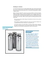
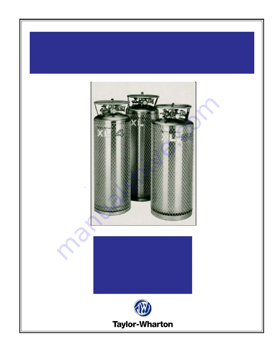
XL-45, XL-50 and XL-55
with Dual Regulator
Instructions for
XL-45, XL-50 and XL-55
with Dual Regulator
Do not attempt to use or maintain this
unit until you read and understand these
instructions. Do not permit untrained
persons to use or maintain this unit. If
you do not fully understand these
instructions, contact your supplier for
further information.
TW-287


