INSTALLATION INSTRUCTIONS
THIS FAUCET MEETS OR EXCEEDS THE FOLLOWING STANDARDS:
cUPC, ASME A112.18.1, NSF-61 AND LOW LEAD COMPLIANT
TURN OFF
TURN OFF
SI
LI
CO
NE
Your installation may require new supply
lines. (Supply lines are not included.)
CUSTOMER SERVICE WEST 1-800-267-4774 | EAST 1-800-387-7064 | taymor.com
® REGISTERED TRADEMARK OF TAYMOR INDUSTRIES LTD.
THANK YOU
FOR PURCHASING THIS TAYMOR PRODUCT. ALL TAYMOR PRODUCTS ARE CAREFULLY
ENGINEERED AND FACTORY TESTED TO PROVIDE LONG TROUBLE-FREE USE UNDER NORMAL CONDITIONS.
HAVE BASIC TOOLS READY
RECOMMENDED TOOLS:
1
Flashlight
Teflon tape Screwdrivers
Adjustable
wrench and
pipe wrench
Plumber’s putty
Safety goggles
Torque wrench
Silicone caulk
6
7
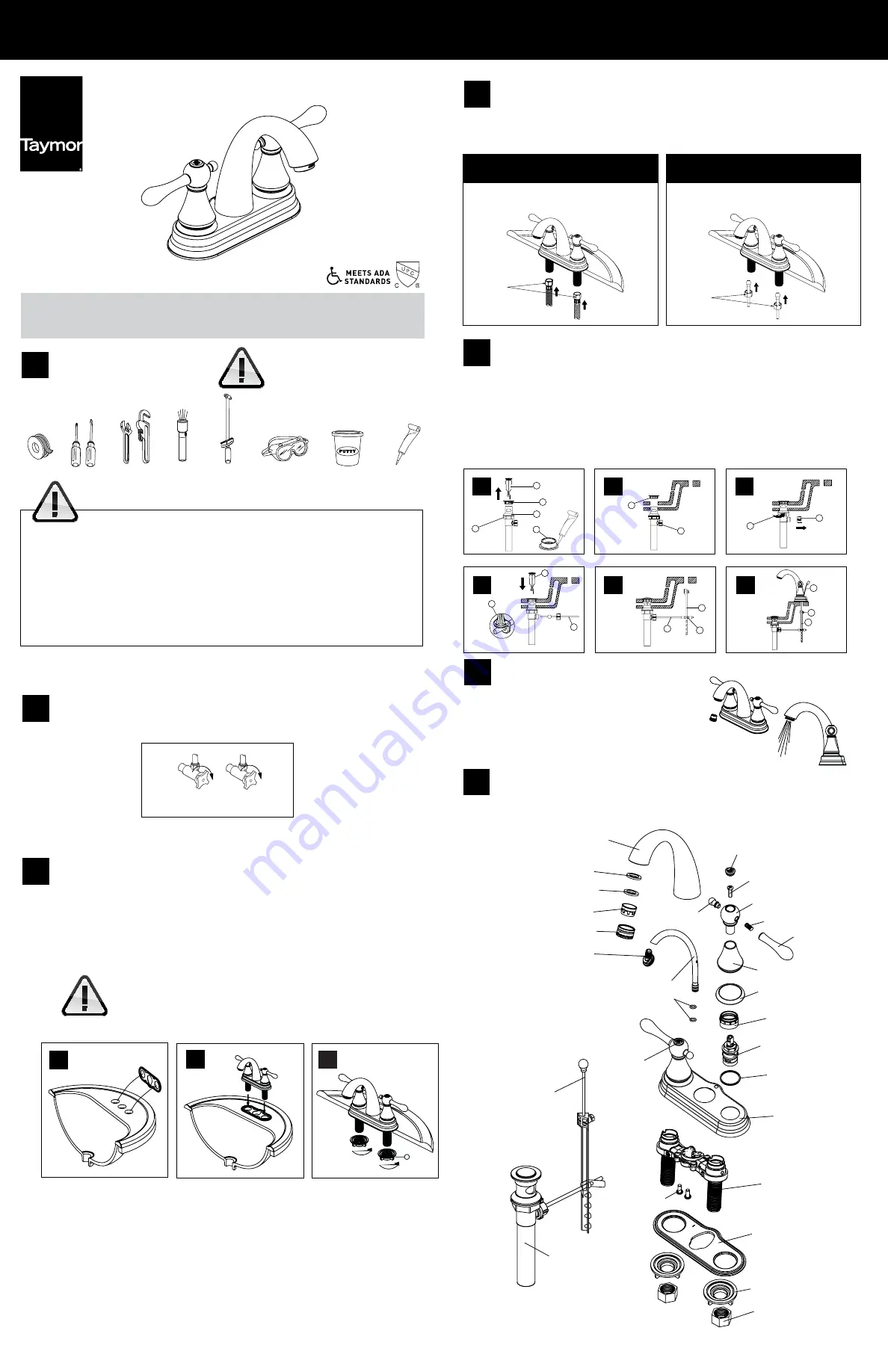
EXPLODED DIAGRAM FOR REFERENCE
MAINTENANCE
Your new faucet is designed for years of trouble-free performance. Keep it looking
new by cleaning it periodically with a soft cloth. Avoid abrasive cleaners, steel wool and harsh
chemicals as these will dull the finish and void your warranty.
FLUSHING & AERATOR CLEANING
Remove the aerator by turning it counterclockwise.
Remove the internal parts of the aerator by pushing them
out with your fingers. Remove any debris. Turn on hot and
cold water supplies. Turn faucet handle all the way on and
run water through the spout for about a minute to remove debris.
While water is running check all connections for leaks. Reassemble the
aerator and screw it back into the spout, hand tighten.
3
2
TURN OFF THE MAIN WATER SUPPLY
Locate water supply inlets and shut off water supply valves. These are usually found under
the sink.
WARNING: READ ALL
the instructions completely before beginning.
READ ALL
warnings, care and maintenance information.
Taymor recommends calling a professional if you are uncertain about installing this product!
This product should be installed in accordance with all local and provincial plumbing and building codes.
Need Help?
Please call our toll-free Customer Support line at
(WEST) 1-800-267-4774 (EAST ) 1-800-387-7064 for additional assistance or service.
BELCARRA 06-4630PSN
TWO HANDLE LAVATORY FAUCET
FAUCET INSTALLATION
1a)
Apply a bead of plumber’s putty or silicone caulk around the sink openings. Install the gasket over the three
holes in your sink.
1b)
Install faucet hoses through the hole of the sink. Centre the faucet body. Make sure that handle is properly
aligned to sink.
1c)
From underneath the sink secure faucet to sink with mounting nuts (1) provided.
Don’t use plumber’s putty on cultured marble or other composite sinks.
Putty will discolour the sink.
1a
1b
A
B
C
D
E
F
A
B
D
C
B
E
E
C
F
A
A
F
G
H
SIL
IC
ON
E
B
5
INSTALLING POP-UP DRAIN
A)
Remove pop-up plunger (A) and flange (B). Screw locknut (C) all the way down. Push gasket (D)
down. Apply silicone to underside of flange (B).
B)
Insert body into sink (from underneath). Screw flange onto body. Pivot hole (E) must face the back
of the sink.
C)
Tighten locknut (C) and gasket but do not overtighten. Remove pivot ball retaining nut (E).
D)
Slide pivot rod (F) into the eye of the pop-up plunger (A). Hand tighten retaining nut.
E)
Slide pivot rod (F) through hole in spring clip (G), then through lever strap (H) and back through
spring clip
.
F)
Insert lift rod (I) down through faucet body and then into lever strap (H). Tighten screw (J). Connect
assembly to drain.
1c
1
I
J
H
1 - INDEX “C”
2 - SCREW
3 - BALL CONNECTOR
4 - CAP
5 - BOLT
6 - HANDLE
7 - HANDLE SEAT
8 - FLANGE
9 - BONNET
10 - CARTRIDGE
11 - WASHER
12 - ESCUTCHEON
13 - BODY
14 - SCREW
15 - BASE PLATE
16 - MOUNTING NUT
17 - COUPLING NUT
18 - SPOUT
19 - WASHER
20 - WASHER
21 - AERATOR
22 - AERATOR SHELL
23 - CONNECTOR
24 - PIPE
25 - O-RING
26 - INDEX “H”
27 - LIFT ROD & KNOB
28 - POP-UP ASSEMBLY
4
ATTACH THE HOT AND COLD SUPPLY LINES
Apply teflon tape onto threaded ends of faucet inlets.
Connect water supply lines to faucet inlets. Hot water supply lines go into left inlet. Cold water supply
lines go into right inlet. (Supply lines and fittings are not included)
FOR BRAIDED PLASTIC AND BRAIDED
STAINLESS STEEL SUPPLY TUBES
FOR 3/8” O.D. BALL-NOSE SUPPLY TUBES
THESE SUPPLY TUBES HAVE INTEGRAL NUTS, SO JUST
SCREW THE NUT ONTO THE FAUCET INLET.
IF THE SUPPLY TUBE END HAS A BULBOUS SHAPE, USE
COUPLING NUTS.
TORQUE
22 – 30 FT/LBS.
TORQUE
22 – 30 FT/LBS.


