background image

User’s Manual

English Version

Konnekt 24D

Konnekt 8

Summary of Contents for Konnekt 24D

Page 1: ...User s Manual English Version Konnekt 24D Konnekt 8...

Page 2: ......

Page 3: ...should be installed near the socket outlet and disconnection of the device should be easily accessible To completely disconnect from AC mains disconnect the power supply cord from the AC receptacle Th...

Page 4: ...t from that to which the receiver is connected Consult the dealer or an experienced radio TV technician for help For Customers in Canada This Class B digital apparatus complies with Canadian ICES 003...

Page 5: ...nel Konnekt 8 15 Rear panel Konnekt 8 15 SETUP EXAMPLES Studio 16 Mobile 18 Live 19 Stand Alone 20 Multiple Konnekts 21 CONTROL PANEL Mixer Page 22 Setup Page 26 DSP Effects settings 30 Routing modes...

Page 6: ...Konnekt 24D and they work even when the unit is used in stand alone mode Konnekt 24D also includes Assimilator Konnekt which is an extremely powerful equalization tool that learns the frequency curve...

Page 7: ...puts 8 ADAT and 2 S PDIF optical and coaxial inputs and outputs Cubase LE included Built in Tuner displayed both via TC Near Control panel and front panel lightring Built in real time DSP effects Fabr...

Page 8: ...n the same FireWire bus You may connect the Konnekt to one of these If you intend to run more FireWire devices simultaneously such as e g an external hard drive we recommend running this device on a s...

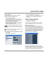
Page 9: ...for Macintosh the VST inputs are not named automatically However you may enter channel names of you choice For Konnekt 24D we suggest using the names as they appear in the screenshot above Cubase Inst...

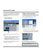
Page 10: ...ettings for the output busses the out is set to BUS 1 Leave it You can now record via the Konnekt front panel inputs and playback via the Main outs Fabrik R as VST send effect The following example il...

Page 11: ...e using Fabrik R as a send or return effect from your host application In this example Cubase Internal mode is the mode to use if you are using Fabrik plug ins from the TC Near Control panel Fabrik C...

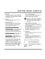
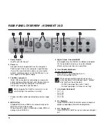
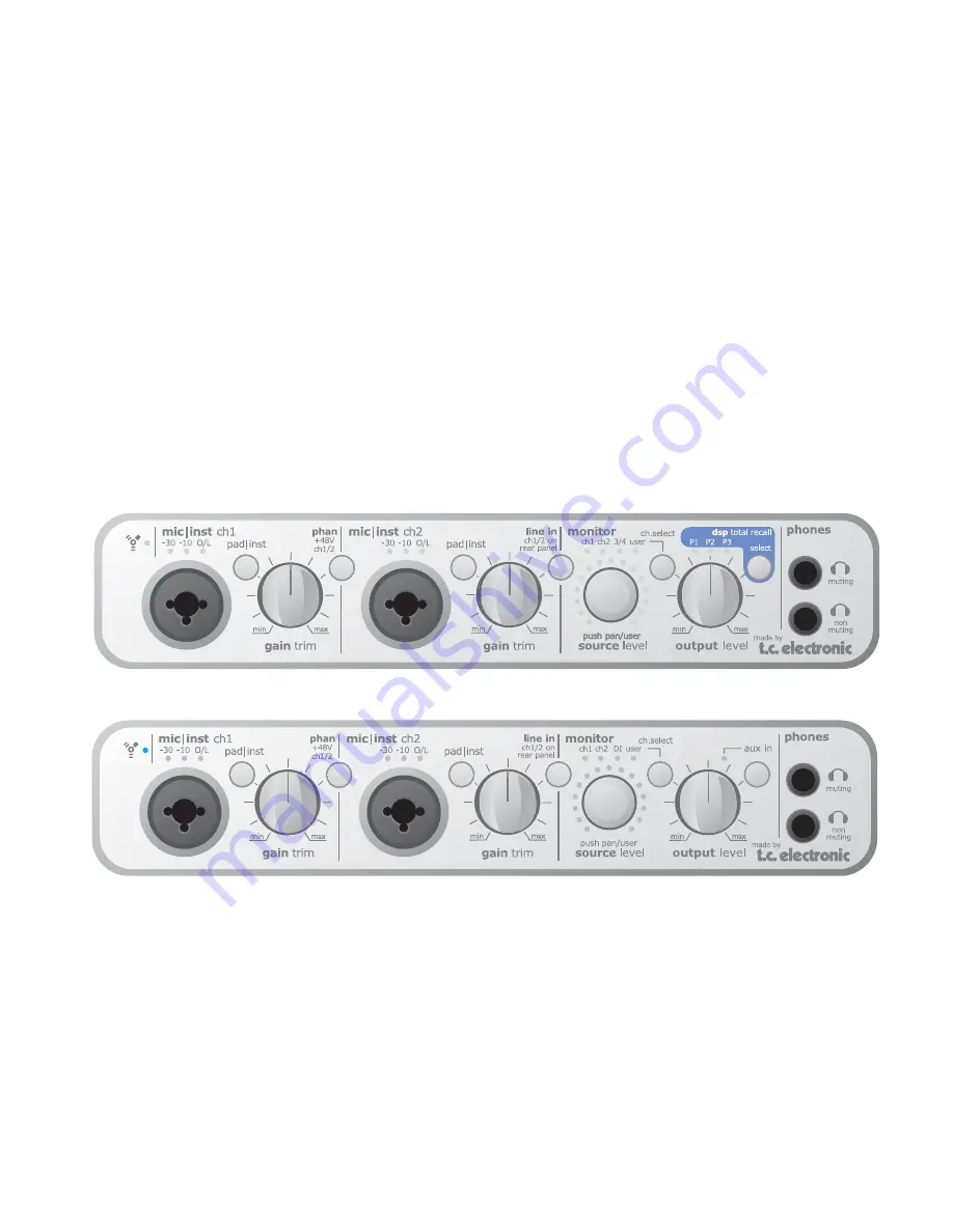
Page 12: ...l is too hot and you should press PAD INST to attenuate the signal by 20dB The 1 4 jack connection Press PAD INST to activate this circuit The 1 4 jack part of the connector is a high quality Hi Z cir...

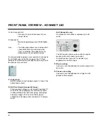
Page 13: ...denser microphone to one of the inputs and connect a guitar using a 1 4 jack to the other input as phantom power only concerns the XLR connections 7 Line In ch 1 2 on rear panel This switch alternates...

Page 14: ...head phone outputs 12 DSP Total Recall Konnekt 24D only Three program settings can be stored in locations P1 P2 and P3 These programs are total recall presets recalling settings from both mixer page...

Page 15: ...ide bus power at all Some laptop computers carry 4 pin connectors These do not provide bus power Several Konnekts on a single FireWire bus If you run more than one Konnekt device on a FireWire bus onl...

Page 16: ...ndard MIDI in out MIDI out is automatically set to MIDI thru in stand alone mode When Konnekt is used in stand alone mode MIDI out always acts as MIDI thru 5 Digital in out Coaxial S PDIF 24bit digita...

Page 17: ...be connected to the aux inputs for monitoring purposes To monitor the aux inputs press the AUX IN button on the front panel Signals present on these inputs cannot be recorded Please refer to the desc...

Page 18: ...SETUP EXAMPLES STUDIO 16...

Page 19: ...tended with the use of an ADAT interface When used in combination with the 2 channels on coaxial S PDIF digital channels 7 8 can be set to either ADAT or optical S PDIF See also page 26 7 Konnekt 24D...

Page 20: ...reWire cable Connect headphones to one of the two headphone outputs The upper connection will mute the main outputs on the rear panes but as nothing is connected to the main outputs it is indifferent...

Page 21: ...l keyboards and or program changes Distribution to PA amp speakers using the SOURCE level control as separate level control Connect all devices according to the illustration above Remember to activate...

Page 22: ...three programs presets using the TOTAL RECALL button The programs are prepared via the TC Near software Control panel Connect the microphone to Ch1 and the guitar to Ch2 on the front panel Activate ph...

Page 23: ...d the others need external power supply In this example all of them use the external power supply Connect the units using standard FireWire cables and connect one of the units to the computer also usi...

Page 24: ...THE CONTROL PANEL MIXER PAGE 22...

Page 25: ...on the input channels Best signal to noise ratio is achieved when the input signal only occasionally peaks at 0 Adjust the level on the sending device 5 Clip LED RED When the Clip LED is lit the signa...

Page 26: ...reverb plug in Fabrik R is set up on a bus that you can send to from each channel The return level of this bus is set using this Effect Return level controller Konnekt 24D only 14 Monitor Mixer Main O...

Page 27: ...y folder on the system including shared folders By default you will be directed to the default location for Konnekt presets Only presets located in the default file locations for TC Near control panel...

Page 28: ...SETUP PAGE 26...

Page 29: ...view Press Stereo Link to link channels 1 and 2 and or 3 and 4 into stereo channels This is an obvious choice when monitoring a stereo source Input Section Digital To process an external digital sign...

Page 30: ...dat 5 6 Adat 7 8 coaxial S PDIF DAW main Fabrik R Level Decay Mixer level dim level Tune Pitch Tone 8 Linked Devices Up to four Konnekt units can be connected You will most likely only monitor the phy...

Page 31: ...onnekt Mixer When Konnekt mixer is selected the main out signal from the Konnekt mixer page is routed to the outputs Mixer Send Knobs On the Konnekt mixer you have the option of sending a signal to th...

Page 32: ...sent on the digital inputs S PDIF Konnekt will attempt to lock to the digital signal present in the S PDIF DI connection Optical Konnekt will attempt to lock to the digital signal present in the ADAT...

Page 33: ...without recording the reverb This is set up the following way Select Internal mode for both Fabrik C and Fabrik R via the Fabrik pages Fabrik C Routing In the DAW VST Input section you may select whic...

Page 34: ...32...

Page 35: ...ls are fixed to mic inst line in 1 and 2 and the output channels are fixed to Main Outs L and R Setting up To use Konnekt with WDM you need to tell Windows that this is your intension Go to Control Pa...

Page 36: ...SYSTEM SETTINGS 34 Access the System Settings page by pressing...

Page 37: ...ster device is always your audio interface However the Clock Master device may sync to an external device See Sync Source below 3 Sync Source The Sync Source parameter determines to which the device t...

Page 38: ...set as clock master External Lock Indicates that the system is locked to an external digital device connected to the Konnekt set as clock master No Reference External sync on the Konnekt set as maste...

Page 39: ...S FIRMWARE UPDATE RESET TO DEFAULT 37 Versions This section gives information on Control panel versions and FireWire driver see page 36 Check for updates If the computer is connected to the Internet y...

Page 40: ...lters choose between 4 different filter types Based on no nonsense design the De Esser is controlled using a single fader With a built in 3 band intelligent compression technique the Compressor is not...

Page 41: ...mode If on the other hand you re working with audio that is within a small frequency area such as e g a trumpet section or background vocals you ll obtain a great advantage using the Full band mode L...

Page 42: ...l peaks that may not be caught and attenuated sufficiently in the Compressor As the Limiter can be used to limit the extreme the Compressor can be used to apply a much more musical and gentle compress...

Page 43: ...nds are set by the selected Source type After the Make up Gain section the signal passes the Limiter Signal Flow Full band mode The signal flow in Full band mode is similar to 3 band mode The differen...

Page 44: ...e BW Type then grab the handle again and move for frequency gain adjustments FABRIK C 42 Bands On Off Grab handle to select Bands On Off Click to activate deactivate the four individual bands Adjustin...

Page 45: ...n filter types Parametric Notch Shelve and Cut For Mid 1 and Mid 2 select between filter types Parametric and Notch Parametric Filter Broad type Shelving Filter FABRIK C 43 Notch Filter Narrow type Cu...

Page 46: ...ilter Lo Gain inf 97dB to 0dB Mid1 Gain inf 97dB to 0dB Mid2 Gain inf 97dB to 0dB Hi Gain inf 97dB to 0dB Range for the Notch filter Lo BW 0 01oct to 1oct Mid1 BW 0 01oct to 1oct Mid2 BW 0 01oct to 1o...

Page 47: ...soft Mix Acoustic Mix Purist Compression 3 band and Full band modes Source page Gain Control The Gain settings are very important The higher set In Gain the harder the signal meets the Compressor Thre...

Page 48: ...f the Compressor and also set the Make up gain on the output the Compression Control adjusts the individual compression amount on the three bands Compression 3 band mode only Compressor Control page L...

Page 49: ...wever a few extra cool features are available Grid On the Source pages the S handle moves in vertical and horizontal directions only but on the Compression Control Level and Gain pages the C L and G h...

Page 50: ...De Esser A De Esser is a compressor type used to reduce only specific sibilant frequencies Typically the ss sounds can be far too dominant on a vocal track and the track would therefore often benefit...

Page 51: ...T facilities Example Typically You would record thru the Fabrik C channel strip adding limited compression and EQ In this case Internal mode should be selected Later when mixing you would probably use...

Page 52: ...each reverb you ll find it very easy to adjust any setting to your own liking You won t waste time with nitty gritty preset adjustments all you really have to worry about is using your ears Main featu...

Page 53: ...and have a listen The Live reverb type also does wonders for vocals or instruments that need a clear and to the point reverb Try it on different material and you ll be surprised with the results Hall...

Page 54: ...BFS and around key values such as 18 20 and 24dBFS is imperative and this distribution takes these key values into consideration O L Overload indication Internal overload is indicated via the O L indi...

Page 55: ...o keep the source material clear and undisturbed by the Reverb Diffuse Field Modulation page The algorithm designers have adjusted the diffuse field part of the reverb to be as smooth and natural soun...

Page 56: ...d distance of a source The less dry the signal compared to Early and Reverb levels the greater the perceived distance Early and Reverb levels set the relation between the amount of room definition com...

Page 57: ...t on a bus The bus is fed from the channels you apply the effect to When used as a send effect the Kill Dry should be set to on and this is also the default setting When used as an insert channel dry...

Page 58: ...onment seamless Integrator offers a plug in audio routing representation of your external digital effects processors and operates as a normal VST AU plug in The Integrator plug in can be inserted on a...

Page 59: ...inserting Integrator on a mono track it still occupies a pair of channels Calibrate Integrating external digital devices will introduce a short latency but your host application can be set up to compe...

Page 60: ...Tuner page Let us take a look at the Tuner page in the TC Near Control panel 1 Tuner Indication In strobe mode Three LEDs are always lit If the played note is too low the LEDs run from right to left...

Page 61: ...ess PLAY TONE if you want to tune acoustically to a reference tone The played note is A according to the set pitch default 440Hz The level of the tone can be adjusted using the small speaker handle lo...

Page 62: ...FW 2 FW 3 FW 4 Phantom 48v S PDIF ADAT or optical S PDIF Gain trim Gain trim Level PAD Impact preamp Gain trim Gain trim PAD Ch 2 main R Ch 3 L Ch 4 R Ch 1 main L From Inputs From DAW FW 6 FW 4 FW 3...

Page 63: ...Line In ch 2 rear AUX ch 3 rear AUX ch 4 rear A D From computer Firewire IEEE 1394 FW 1 FW 2 Phantom 48v S PDIF S PDIF Gain trim Gain trim Level PAD Impact preamp Gain trim Gain trim PAD Ch 2 main R...

Page 64: ...inst line 2 2 Mic inst line 2 3 Coaxial L 3 Coaxial L 3 Coaxial 4 Coaxial R 4 Coaxial R Outputs Outputs Outputs 1 Line 1 Main L 1 Line 1 Main L 1 Line 1 Main L 2 Line 2 Main R 2 Line 2 Main R 2 Line...

Page 65: ...ADAT 3 11 12 ADAT 4 12 ADAT 4 12 13 ADAT 5 13 13 14 ADAT 6 14 14 15 ADAT 7 Coaxial L 15 Coaxial L 15 Coaxial 16 ADAT 8 Coaxial R 16 Coaxial R 16 Outputs Outputs Outputs 1 Line 1 Main L 1 Line 1 Main L...

Page 66: ...erfectly align all digital signals from external digital sources This means that all supported digital formats will be aligned to ensure maximal digital quality JET patent pending Next generation of j...

Page 67: ...A 106 dB 20 Hz to 20 kHz Neutrik Combo 1 4 Phone Jack 25 dBu 17 dBu 42 dB 1 Mohm 100 dB 0 001 1 kHz 1 dBFS 107 dB A 104 dB 20 Hz to 20 kHz 100 dB 20 Hz to 20 kHz Monitor Line Outputs Ch 1 2 3 4 5 Conn...

Reviews: