
Instruction Sheet
AMPLIMITE* High Density (HDP- 20)
408--7514
LOC B
1
of 2
E
2011 Tyco Electronics Corporation, a TE Connectivity Ltd. Company
All Rights Reserved
TE logo is a trademark.
*Trademark. Other product names, logos, or company names might be trademarks of their respective owners.
TOOLING ASSISTANCE CENTER 1--800--722--1111
PRODUCT INFORMATION 1--800--522--6752
This controlled document is subject to change.
For latest revision and Regional Customer Service,
visit our website at
www.te.com
10 Mar 11 Rev E
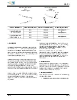
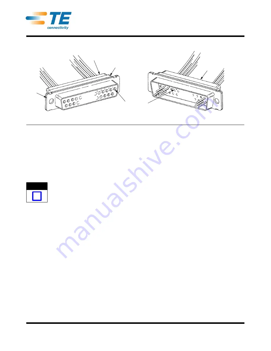
Connectors with Crimp- Type Contacts
Figure 1
Shell
(Ref)
Insert
(Ref)
Receptacle
Connector
(Front)
Numbered
Cavities
Plug Connector
(Back)
1. INTRODUCTION
This instruction sheet covers contact and wire
selection, application tooling, and attaching hardware
for AMPLIMITE High Density (HDP--20) Connectors
shown in Figure 1. Read these instructions thoroughly
before assembling any connectors.
All dimensions on this document are in metric
units [with U.S. customary units in brackets].
Figures and illustrations are for reference only
and are not drawn to scale.
Reasons for reissue of this document are provided in
Section 6, REVISION SUMMARY.
2. DESCRIPTION
(Figure 1)
The connectors are designed for rear insertion and
extraction of size 20, precision formed contacts. The
HDP--20 connectors feature steel shells and black
polymer inserts with plastic contact retention tines.
3. CONTACTS
(Figure 2)
3.1. Selection
Refer to the table in Figure 2, and select strip or
loose--piece pin and socket contacts according to the
wire size and insulation diameter to be used.
Notice that each contact cavity is number--coded
(front and back). Make certain that the cavities of the
plug are a mirror image of the receptacle. Insert pin
contacts into the back of plug and mating socket
contacts into the back of the receptacle. If all cavities
are not used, distribute contacts evenly throughout
connector.
3.2. Crimping
Strip--form contacts are designed to be crimped with a
semi--automatic or automatic machine and applicator.
Consult your local TE Representative for assistance
in selecting the machine and applicator for your
application.
Loose--piece precision formed contacts are designed
to be crimped with the hand crimping tools listed in
the table in Figure 2. Refer to the instruction sheet
packaged with the tool, for specific crimping
procedure and tool inspection information.
3.3. Insertion and Extraction
Insertion/Extraction Tools 91067--2 (Instruction Sheet
408--7508) and 91285--1 (Instruction Sheet
408--9404) are designed for both pin and socket
contacts. The 91067--2 tool is used with contacts for
wire size 24 to 20 AWG and the 91285--1 tool is used
with contacts for wire size 28 to 24 AWG.
NOTE
i


