background image

SL-D90

AM/FM STEREO DIGITAL 

1  SAFETY INFORMATION

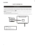
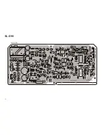
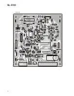
PC board shown are viewed from parts side.

The parts with no reference number or no parts number

in the exploded views are not supplied.

As regards the resistors and capacitors, refer to the

circuit diagrams contained in this manual.

Parts marked with this sign are safety critical

components. they must be replaced with identical

ensure exact replacement.

!

components - refer to the appropriate parts list and

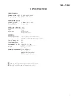
2  SPECIFICATIONS

4  EXPLODED VIEW AND PARTS LIST

5  PC BOARDS AND PARTS LISTS

6  WIRING DIAGRAM

7  INCLUDED ACCESSORIES

 2

 3

 7

13

23

25

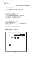
3  ADJUSTMENT AND CHECKS

 4

RADIO WITH CD PLAYER 

Parts of [ ] mark can be used only with the version designated.

[UL/CSA]: T/C    [ME/UNI]: EX/T   [JIS]: DM   [IT]: EUR  

[HK]: UK/HKG

Summary of Contents for SL-D90

Page 1: ...this manual Parts marked with this sign are safety critical components they must be replaced with identical ensure exact replacement components refer to the appropriate parts list and 2 SPECIFICATIONS...

Page 2: ...nvisible laser radiation emitted inside of this product is completely confined in the protective housings The label required in this regulation is shown 1 CAUTION SL D90 1 CERTIFICATION THIS PRODUCT C...

Page 3: ...D Weight Standard Accessories Warranty Card x 1 340 x 190x 238 5 mm 5 15 kg 11 3 8 lb 120V AC 60Hz U S A Canadamodel Power Consumption CD PLAYER Section Frequency Response 20 Hz to 20 kHz 1dB Wow and...

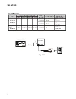
Page 4: ...enerator 4 Connect theoscilloscope to thePHONES JACK terminal 3 1 1 AM adjustment 5 Set the signal generator as listed in the alignment chart 1 Set the function switch to the TUNER position 3 Connect...

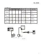
Page 5: ...S RESULT Audio Modulation Frequency Output 1 VOLTAGE adjustment 2 IFT adjustment 3 ANT coil adjustment 4 TC1 adjustment 1710KHz 530 KHz 610KHz 30 1KHz 1410KHz L6 TC1 AM ant coil Check L4 VT Repeat ste...

Page 6: ...Audio Modulation Frequency Output 1 VOLTAGE adjustment 2 IFT adjustment 106 1MHz 90 1MHz 22 5KHz 1KHz L5 Check VT 25 dBuV 5 5 5 9V SETTING VT 1 2 1 6V output level Maximum 90 1MHz 90 1MHz Check FM si...

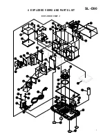
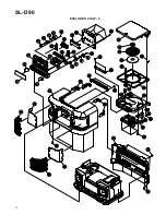
Page 7: ...D VIEWS AND PARTS LIST EXPLODED VIEW 1 1 2 3 4 6 7 8 9 9 5 11 12 13 14 14 14 14 15 16 16 17 19 20 20 18 21 22 23 23 25 24 26 29 30 28 31 32 33 33 34 35 36 37 39 39 40 38 41 41 41 42 42 43 44 10 10 35...

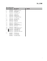
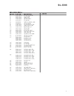
Page 8: ...HKG HEAT SINK BRACKET MAIN PCB ASSY 100 SD902010 011 SD900100 CD PCB SHIELD PLATE 100 SD902040 TUNER PCB ASSY 010 SD900000 SPEAKER BOX ADIABATIC SHEET 015 SD900100 SPEAKER 2 INCHES 061 SD900800 R L S...

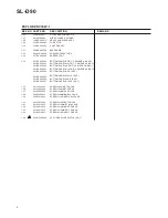
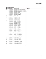
Page 9: ...UK HKG 001 SD900201 BOTTOM PANEL WHITE T C DM EUR UK HKG 001 SD900200 BOTTOM PANEL RED T C DM EUR UK HKG 1 31 1 32 1 33 1 34 1 35 1 36 1 37 1 38 1 39 1 40 1 41 1 42 1 43 1 44 004 SD900700 BASE KNOB S...

Page 10: ...SL D90 EXPLODED VIEW 2 1 2 3 4 6 6 7 7 8 9 5 5 11 12 13 13 14 15 16 17 19 20 18 21 22 23 25 24 26 27 29 30 28 31 32 33 34 35 35 36 37 39 39 40 40 40 38 41 41 42 43 44 45 46 10 46 10...

Page 11: ...0 008 0GP18000 GEAR DUMPER ASSY 009 28000000 POWER KNOB CAP 010 SD901500 010 SD900100 010 SD900200 010 SD900500 010 SD900700 VOLUME SPRING COVER 010 SD900800 TUNER SPRING COVER 010 SD901200 010 SD9013...

Page 12: ...PANEL BLACK DM BACK PANEL RED EUR BACK PANEL WHITE EUR BACK PANEL JADE EUR BACK PANEL BLACK EUR BACK PANEL RED UK HKG BACK PANEL WHITE UK HKG BACK PANEL JADE UK HKG BACK PANEL BLACK UK HKG SNOOZE KNO...

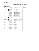
Page 13: ...CN6 082 20500100 CONNECTOR 5PIN P 2MM CN7 082 20300100 CONNECTOR 3PIN P 2MM CN11 19 082 20540100 CONNECTOR 5PIN P 2 5MM D9 15 22 077 00414801 DIODE IN4148 MAIN PCB ASSY DESCRIPTION IC3 075 00405201 IC...

Page 14: ...13 R115 R116 R117 R118 R124 R125 R126 R123 C70 R103 R106 R105 C71 C72 R101 R99 R97 C84 R122 R96 C78 R94 R89 C75 C 7 3 J34 J30 J31 R104 R95 R93 R91 C76 C74 R88 R86 R100 R102 C81 R90 R98 R92 J33 J29 Q1...

Page 15: ...ONNECTOR 30PIN P 1 25MM CN16 082 20400100 CONNECTOR 4PIN P 2MM CN18 082 21600305 CONNECTOR 16PIN P 1MM D201 206 077 00414801 DIODE IN4148 IC9 075 094A0931 IC TC94A09F 202 IC10 075 00209001 IC TA2092N...

Page 16: ...235 R237 R236 R238 C253 C252 J010 R218 R217 J030 J09 R232 R250 R230 J031 C258 C251 C220 C217 C244 J036 C243 C242 C241 J01 J041 J054 R206 R203 C202 R202 R201 C204 C203 C207 C210 C209 C211 C212 C213 C21...

Page 17: ...4801 DIODE IN4148 F001 054 0GP18000 FM ANT FILTER GFMB3 IC1 075 00145008 IC BA1450S IC2 075 09257F21 IC TC9257F 095 10220001 INDUCTOR 220UH L2 079 D2930210 AM OSC COIL RED L4 079 SLD90020 FM DET COIL...

Page 18: ...R160 R159 CF1 R146 C111 L6 C120 C121 J102 R154 R155 R157 R153 R150 C118 C117 R149 Q28 C103 ZD3 Q27 R143 C105 J105 C101 J103 C123 R166 C142 D17 D16 D18 J107 J108 J113 C119 D19 R180 J100 R145 R142 R141...

Page 19: ...SD902020 CONTROL PCB ASSY 062 SLD90001 CONTROL PCB LED01 03 094 03020301 LED 3MM ORANGE 076 00C94500 TR 2SC945 Q301 304 080 SLD90021 LCD DISPLAY LCD1 SW01 04 10 012 SW014 018 063 0GP28020 TACH SWH 5M...

Page 20: ...016 CD SW04 AUX SW06 TUNER SW05 T UP SW011 R308 VOL DN SW03 J301 R320 R322 R321 Q301 Q303 Q302 Q304 DOWN SW012 STOP SW08 R313 J318 J310 J309 J307 J304 U01 R323 J303 R328 J3O2 J305 R333 R305 TU DN SW01...

Page 21: ...3PIN P 2MM 082 10300100 CN9 JK02 086 SLD90020 AUX JACK RJ 1095 SNOOZE PCB VOLUME 50KB C 069 SD901000 VR1 SL D90 21 REMARK REMARK REF NO PARTS NO DESCRIPTION CD SWITCH PCB ASSY 100 SD902060 CD SWITCH...

Page 22: ...NOOZE SW021 OPEN CLOSE SW022 CN9 IN G OUT CW8 JK02 CW1 CW16 CW14B RESET SW023 CW14A JK01 CW7 R G L VR1 REV 00 94 HB AUX JACK PCB REV 00 PHONE JACK PCB 94 HB CD SW PCB 2002 6 1 94 HB REV 00 SL D90 SNOO...

Page 23: ...0 23 CN1 CN15 CN11 CN19 CN6 CN7 CN2 CN3 MAIN PCB CN4 TO TRANSFORMER TO SPEAKER P TO WOOFER TO SPEAKER L TO PHONE JACK CW1 TO TUNER PCB CW1 1 TO CD PCB CW6 TO AUX JACK PCBCW7 TO CD PCB CN5 6 WIRING DIA...

Page 24: ...24 CN17 CN16 CN18 CW10 CN12 CD PCB SL D90 TO CD SWITCH PCBCW16 TO CONTROL PCB CW12 TO CD PICK UP TO CD DECK MOTOR TO TUNER PCB CN10...

Page 25: ...TION INCLUDED ACCESSORIES GUARANTEE SHEET INSTRUCTION BOOK E F T C 047 D2831000 046 SLD90000 REMARK INSTRUCTION BOOK S P EX T 046 SLD90010 INSTRUCTION BOOK J DM 046 SLD90020 INSTRUCTION BOOK I S EUR 0...

Page 26: ...TEAC MEXICO S A De C V TEAC UK LIMITED TEAC DEUTSCHLAND GmbH TEAC FRANCE S A TEAC NEDERLAND BV 7733 Telegraph Road Montebello California 90640 Phone 323 726 0303 5939 Wallace Street Mississauga Ontar...

Page 27: ...C19 100UF R27 4K7 R26 47K R25 10K R17 1M C58 1UF R31 3K3 R121 10K Q14 2SC945 R59 2K2 R58 2K2 CN9 CW9 1 2 3 VR1 50KB WOOFER IN GND WOOFER OUT AUX JACK PCB WOOFER VR C57 47UF C54 10UF C53 1UF C56 47UF...

Page 28: ...11 104 C212 15P C213 15P XT3 16 9344MHz C232 473 C233 473 C234 473 C235 473 C236 470P R207 3K3 C237 470P R255 1K C222 103 C221 47UF C220 47UF C219 47P C218 153M R209 15K C217 103 C215 472 C216 272M R2...

Page 29: ...332 15K R306 10K Q301 2SC945 R319 2K2 SW02 VOL UP SW03 VOL DN SW04 CD R321 10K R320 12K SW05 TUNER SW06 AUX R322 27K IR01 IR333 SW018 TIMER SLEEP R325 3K9 R324 2K2 CW12 REMOTE 5 7V GND POWER TU PWR AD...

Page 30: ...3 Detach the Rear Case from the Front Case 4 Remove screws from the Main PCB Assy and the Heatsink 5 indicated by Red 1 indicated by Red from the Heatsink...

Page 31: ...The Main PCB A is detached and lying down by disconnecting the following cables Disconnect all the cables with connector Power cables from the Power X mer 3 at Left side From Headphone 3 from Speaker...

Page 32: ...m TUNER PCB A and AUX PCB A 6 Disconnect cables from CD Drive unit and CD PCB A This connector is inside of the Main body at right hand side FFC from CD PCB A The Pickup FFC can be extracted at one of...

Page 33: ...e Main body by fulfilling above steps 8 Set the section upside down to remove 4 mounting screws 9 The CD Drive unit Traverse unit is now replaced with detaching the Cover Extract this section as the C...

Page 34: ...replaced after removal of CD Drive unit by the following steps 11 4 metal brackets have to be detached Insert driver to release a latch of the bracket inside and extract it Treat same manner to detac...

Page 35: ...e Front Case from the Main body to view the mounting screw of the Power X mer As there is a headphone unit at right hand side mind to reserve some space there 13 The Power X mer is now replaced by rem...

Reviews: