background image

T E A M   K I T

S P O R T   K I T

B A S I C         K I T

Shocks: Hard anodized,

PTFE

-

coated gray.

Rear Axles: MIP CVD's.

Also includes: Ball bearings 

throughout.

Shocks: Gold shocks.

Rear Axles: Associated dogbones & 

stub axles.

Also includes: Mechanical speed 

control and motor. Bushings 

throughout.

Shocks: Gold shocks.

Rear Axles: Associated dogbones & 

stub axles.

Also includes: Bushings 

throughout.

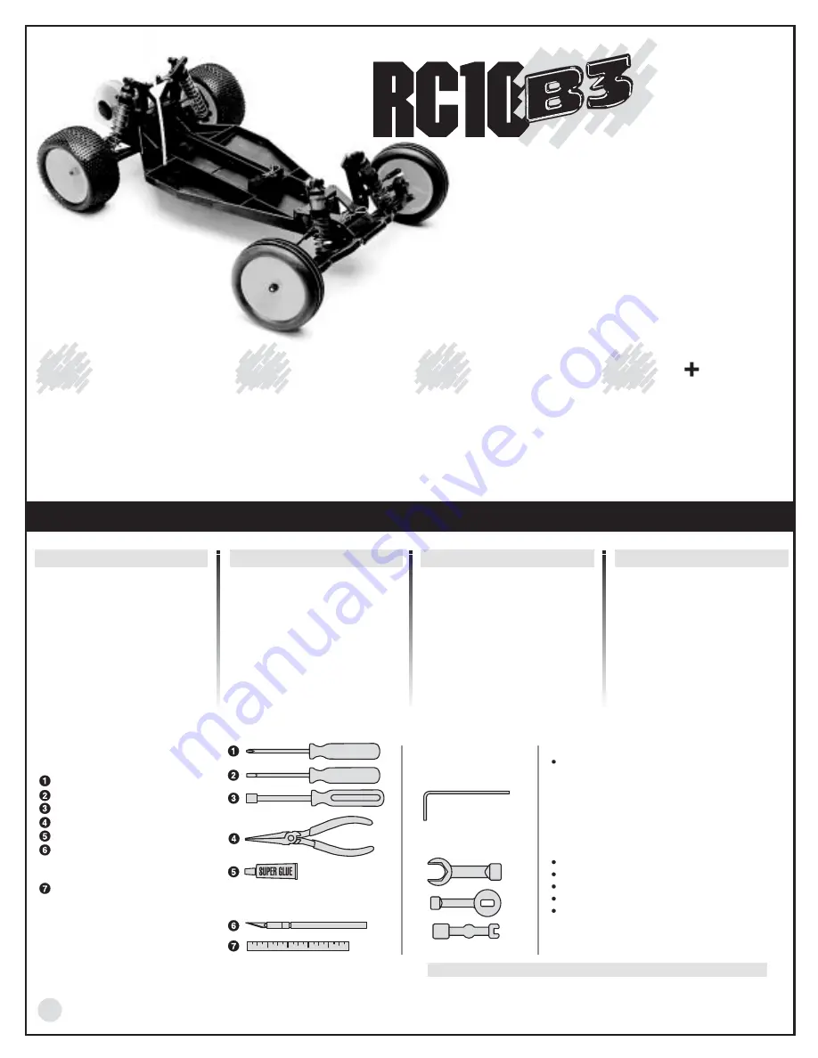
All kit versions include:
2.40:1 transmission for effortless power handling.
Molded composite chassis for better rigidity and Lexan B3 racing body.
Quadra-symmetric suspension for greater stability and handling.
Optimized front end geometry improves steerging and increases rigidity.
Adjustable battery placement for fine tuning of traction or steering.
2.2" one-piece front and rear wheels.
Pro-Line 4 Rib M2 front tires and Pro-Line "Holeshot" M2 rear tires.

F A C T O R Y   T E A M

Shocks: Hard anodized,

PTFE

-

coated gray.

Rear Axles: MIP CVD's.

Also includes: Factory Team 

parts, ball bearings throughout.

2

YOU WILL NEED THESE TOOLS
TO ASSEMBLE YOUR KIT

Phillips screwdriver #2.
1/8" flat head screwdriver.
5/16" driver or glow plug wrench.
Needlenose pliers.
Super glue (cyanoacrylic glue).
Hobby knife 

WARNING! This knife

cuts plastic and fingers with equal
ease, so be careful.

Precision ruler.

WARNING! Always use hand and eye 
protection with cyanoacrylic glue!

for the

B3 Basic+ kit #9003

R/C two channel surface 
frequency radio system
with one servo.
Battery pack (6 cell).
Battery charger (we recommend
a peak detection charger).
Electronic speed control.
Pinion gear, 48 ptich. Teeth to be 
determined by type and wind of
motor.

R E Q U I R E D   E Q U I P M E N T   T O   R U N   Y O U R   K I T

for the

B3 Sport kit #9013

R/C two channel surface 
frequency radio system
with two servos.
Battery pack (6 cell).
Battery charger (we recommend
a peak detection charger).

for the

B3 Team kit #9032

R/C two channel surface 
frequency radio system
with one servo.
Battery pack (6 cell).
Battery charger (we recommend
a peak detection charger).
Electronic speed control.
R/C electric motor. 
Pinion gear, 48 ptich. Teeth to be 
determined by type and wind of
motor.

TOOLS SUPPLIED

Allen wrenches, .050", 
1/16", 3/32", 5/64".

Molded tools (#6956):

for the

Factory Team kit #9043

R/C two channel surface 
frequency radio system
with one servo.
Battery pack (6 cell).
Battery charger (we recommend
a peak detection charger).
Electronic speed control.
R/C electric motor. 
Pinion gear, 48 ptich. Teeth to be 
determined by type and wind of
motor.

HELPFUL TOOLS (NOT REQUIRED)
Allen drivers (straight Allen wrenches with hex 
shaped handles) such as the following made by 
Associated:
#6957 

.050" Allen wrench

#6958 1/16" 

Allen 

wrench

#6959 5/64" 

Allen 

wrench

#6960 3/32" 

Allen 

wrench

#6961 2.5mm 

Allen 

wrench

Hand drill with 1/8" & 1/4" bits
Vernier calipers
Hobby scissors
Liquid dish soap
Nut drivers (screwdriver-handled hex socket 
tools) such as the following from Associated:
#SP-86  3/16" nut driver
#SP-85  1/4" nut driver

WARNING!

Do not use a power screwdriver to install screws into nylon, plastic, or
composite materials. The fast rotation speed can heat up the screws being
installed. They can then break the molded parts or strip the threads during
installation.

Summary of Contents for RC10 B3 Basic+

Page 1: ...detection charger Electronic speed control Pinion gear 48 ptich Teeth to be determined by type and wind of motor R E Q U I R E D E Q U I P M E N T T O R U N Y O U R K I T for the B3 Sport kit 9013 R C two channel surface frequency radio system with two servos Battery pack 6 cell Battery charger we recommend a peak detection charger for the B3 Team kit 9032 R C two channel surface frequency radio s...

Page 2: ...ontacting us for help Hello Associated I need some help Did you read the manual OPEN THE BAGS IN ORDER The assembly is arranged so that you will open and finish that bag before you go on to the next bag Sometimes you will have parts remaining at the end of a bag These will become part of the next bag Some bags may have a large amount of small parts To make it easier to find the parts we recommend ...

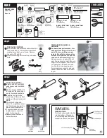
Page 3: ...13 6936 and 6295 Do other side Attach the 9145 ball ends and 7260 nuts through middle holes Attach the shock tower to the bulkhead with the three 6924 screws Twist 7230 ball cups onto the 6263 1406 turnbuckle until you get the dimension shown Connect ball ends with the turnbuckle ball cups as shown using your needlenose pliers 7413 qty 2 4 40 x 3 4 6936 qty 2 4 washer 6295 qty 2 4 40 nut 6924 qty ...

Page 4: ...aver arm 9155 qty 2 bell crank bushing 9158 9156B qty 1 tube aluminum 9158 9156B qty 1 adjusting nut 9158 qty 1 servo saver spring 9155 qty 1 bell crank 9165 qty 1 drag link DRAG LINK Install the 9165 drag link over the two ball ends with your needlenose pliers 1 1 1 1 1 1 1 1 1 1 1 1 1 1 1 1 9210 9210B qty 1 kickup T O O L S U S E D s t e p 2 5 s t e p 3 P R O F I L E IFMAR 2WD World Champion Mas...

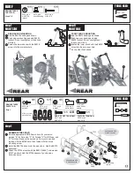
Page 5: ... bumper 7673 6933 qty 2 4 40 x 5 16 1 1 1 1 1 1 BUMPER TO CHASSIS Use two 6922 6934 screws to secure the top plate to front bulkhead FRONT END TO CHASSIS Slip front end under top plate then push rearward over kickup T O O L S U S E D s t e p 4 1 16 s t e p 5 6 s t e p 6 REMOVE THESE PARTS FOR Steps 4 6 6922 6934 qty 2 4 40 x 1 2 1 1 6922 6934 9130 9131 6923 6923 under top plate 6292 6292 9220 7673...

Page 6: ...p 7 7 P R O F I L E Ranch Pit Shop The RC10B3 TQ d as the fastest car in the World s on this track in Pomona California site of the 1997 IFMAR Off Road World Championships The B3 was driven by Masami Hirosaka multi World Champion from Japan The B3 was later to come back to TQ and win at the very next 99 World s at Finland REMOVE THESE PARTS FOR Step 7 ball cups thread on in opposite directions 2 4...

Page 7: ...thread on the 7260 nuts to the ball ends Then add the 6272 foam dust covers SUSPENSION ARMS TO MOUNTS Attach the 9257 9258 left suspension arm to the 9267 left mount with the 9260 hinge pin and 6299 E clips Now do the right side s t e p 1 8 s t e p 3 L E F T S I D E 9257 9258 qty pr rear suspension arm 9267 qty 2 rear suspension mount 3 3 3 toe in 3 anti squat 9260 qty 2 rear inner hinge pin 9241 ...

Page 8: ... drive ring and then the gear assembly on the hub ASSEMBLE THE HUBS Add a light coat of 6591 diff lube to left hub where shown Place a 9367 diff drive ring on the hub Push the 9370 hub over the diff bolt and center the hub CHECK ALIGNMENT OF HUBS Tighten the diff with your 5 64 Allen wrench but not completely Rotate the diff hubs several times as you are tightening the bolt to check for proper ali...

Page 9: ... of a turn No more no less Your diff should now operate very smoothly when turning the hubs in opposite directions After you have driven the car once recheck the diff adjustment Never adjust the diff any other way INSIDE THE TRANNY Install the right side diff assembly into the right case Page 9 Step 3 will show you which diff hub is the right side Add the 7669 spacer to the 6571 drive shaft and pu...

Page 10: ... initial adjustment For further info on the torque clutch see the tuning section on page 27 MOUNT THE TRANSMISSION Mount the 9380 brace with two 7874 7873 screws Mount the tranny with the two 6292 6934 screws from below lining up the motor plate holes as shown Bolt the motor plate to the rear chassis with two 6568 screws 6587 qty 1 torque control spring 6629 qty 1 5 40 locknut 1 1 6594 qty 2 thrus...

Page 11: ...ne washer as shown raised outer edges facing out Add 6375 roll pin Insert the 6372 spring into the stub axle Thread on the 6273 ball end and add the 7260 nut to the other side When you do the other hub carrier thread the ball end into the other side so both will point to the front when assembled Add a 6272 dust cover to the ball end Follow the above for the right hub carrier 6272 qty 2 dust cover ...

Page 12: ...3 16 axle shim steel 7369 qty 2 axle spring pin 1 1 1 1 T E A M F A C T O R Y T E A M K I T S O N L Y s t e p 1 L E F T S I D E 13 7377 3977 qty 4 3 16 x 3 8 ball bearing REMOVE THESE PARTS FOR Team step 1 Factory Team step 1 7366 qty 2 hub carrier 9257 9258 6299 9263 6299 9263 R E A R 7366 REAR HUB CARRIERS Note that the 7366 hub carriers are marked left and right Slide one of the thin 7368 3 16 ...

Page 13: ...ansmission brace with the 6915 screws Add two 7413 screws in the middle holes at top then thread on 7260 nuts 1 1 7413 qty 2 4 40 x 3 4 1 1 7260 qty 2 4 40 nut 14 s t e p 2 L E F T S I D E R E A R V I E W 1 16 3 32 A L L K I T S COMPLETED REAR ASSEMBLY s t e p 3 ADD TURNBUCKLES Twist 7230 ball cups onto the 6262 1403 turnbuckle until you get the dimension shown Ball cups will face in opposite dire...

Page 14: ...shaft 6460 6418 qty 2 front shock shaft 5407 qty 8 red O ring 6429 qty 1 shock assembly tool 6440 qty 4 split locking washer 6440 qty 4 large spacer 6440 qty 8 small washer 6465 qty 2 shock piston 1 6428 qty 4 shock cap 6469 qty 4 large O ring 6299 qty 8 E clip TEAM F T ONLY 6435 qty 2 rear shock body BASIC SPORT ONLY 6424 qty 2 rear shock body TEAM F T ONLY 9310 qty 2 front shock body BASIC SPORT...

Page 15: ... t e p 3 FOR BASIC SPORT front 9311 gold short rear 6424 gold long FOR TEAM F T ONLY front 9310 short rear 6435 long HOW TO TIGHTEN THE CAP ON YOUR SHOCK Then the shaft should push itself out approximately 1 4 to 3 8 6 3mm 9 5mm If the shocks do not push out this far there is not enough oil in them Add just a little oil and try steps 6 7 again If the shocks push out farther than the distance in st...

Page 16: ...for Airtronics F for Futaba J for JRPropo and H for Hitec Remove the servo horn from your servo and replace with the 9180 horn then fasten with the stock mounting screw Install the 6270 ball end into the servo horn Add the 6272 dust cover Attach the 7336 mounts with the 6917 6860 screws and 7337 washers Add the 7336 spacers if you have an Airtronics servo 6270 qty 1 ball end 6272 qty 1 dust cover ...

Page 17: ...lat side of the shaft For the Basic Team Factory Team kits you must buy your own pinion gear If you use an electonic speed control see its directions for installing motor capacitors Use two 6515 screws and two 6936 washers to mount the motor as shown so the gears mesh SET THE GEAR MESH You should be able to rock the spur gear back and forth in the teeth of the pinion gear without making the pinion...

Page 18: ... the 6714 mount with a 6924 screw and 6936 washer 6932 qty 6 4 40 x 5 16 1 1 6936 qty 7 4 washer 8850 qty 1 ea throttle resistor mounting brackets 6711 qty 1 throttle resistor 6712 qty 1 throttle wiper arm 6714 qty 1 throttle bypass mount 6925 qty 1 4 40 x 1 2 6714 qty 1 throttle bypass tab 6924 qty 1 4 40 x 3 8 1 1 1 1 1 1 RESISTOR TO SERVO Push the 8850 brackets into the 6711 resistor Attach the...

Page 19: ...917 qty 2 4 40 x 3 8 1 1 PARTS REMOVED TO IMPROVE CLARITY RADIO RECEIVER TO CHASSIS Cut a piece of servo tape remove the paper from one side and attach it to the bottom of your receiver Slip the receiver wire through the built in chassis antenna mount Remove the paper from the other side and attach to the chassis as shown Plug the small 6747 BEC plug of step 7 into the receiver s on off switch Fol...

Page 20: ...d down strap Adjust the screw so the batteries are held tight but you are still able to push the 6332 body clip through the screw 9247 qty 1 gear cover 9247 qty 1 button 9235 qty 1 foam battery pads 9238 qty 2 battery spacer 6929 qty 1 4 40 x 3 8 1 1 9230 9229 qty 1 battery hold down strap 6332 qty 1 body clip SOLDERING INDIVIDUAL CELLS Solder connections properly to assemble a battery pack from i...

Page 21: ...d steering servo to your receiver according to your radio or ESC instructions then connect the motor to your ESC qty 1 servo tape T O O L S U S E D s t e p 3 MOUNT THE ANTENNA Push your reciever wire through the built in antenna mount hole Thread the wire through the 6338 antenna and push the antenna firmly into the chassis antenna mount hole Add the 6338 cap to the other end of the antenna tube 6...

Page 22: ...0 use inner holes cut 6 openings for body these openings allow for shocks air scoop body mount body wing mounts antenna 6142 qty 1 body B A S I C S P O R T K I T S O N L Y REMOVE THESE PARTS FOR Team F T Step 5 6193B qty 2 wing thing 9454 qty 1 065 wing wire 6154 qty 1 wing 4436 qty 2 4 40 x 5 16 1 1 6332 qty 2 body clip T O O L S U S E D B A G H 050 6154 qty 1 body T E A M F A C T O R Y T E A M K...

Page 23: ...nufacturer s instructions for proper use and safety Wear eye and hand protection Insert the 6599 bushings or 3799 bearings into both sides of the front wheel Install wheel onto axle Thread on 6222 locknut Finish second front wheel and tire 9481Y or 9482 6878 6599 or 3977 6222 REAR WHEELS AND TIRES Make a 1 8 hole in the wheel Make sure foam insert is centered in tire Install the 6825 tire to the 9...

Page 24: ... SERVO _____________ FRONT BLOCK CARRIER caster setting 25 30 FRONT RIDE HEIGHT ________________________ STEERING BLOCK _______ ___________________ CAMBER ___________________________________ ANTI ROLL BAR NONE THICK THIN OTHER FRONT SUSPENSION _ FRONT SHOCKS REAR SUSPENSION SUSPENSION MOUNTS 2 3 3 3 3 0 WHEEL HUB STANDARD OTHER REAR RIDE HEIGHT _________________________ ANTI SQUAT STD OTHER ______...

Page 25: ... coated gray shocks Team and Factory Team kits only MIP CVD axles Team and Factory Team kits only Molded composite chassis Basic Sport and Team kits only Graphite chassis towers and arms Factory Team kits only Adjustable caster camber toe in Extra long suspension arms front rear 2 40 1 transmission Motor Basic Plus Sport kits only Factory Team performance parts Reedy Modifieds motors batteries LRP...

Reviews: