background image

Summary of Contents for Junior T

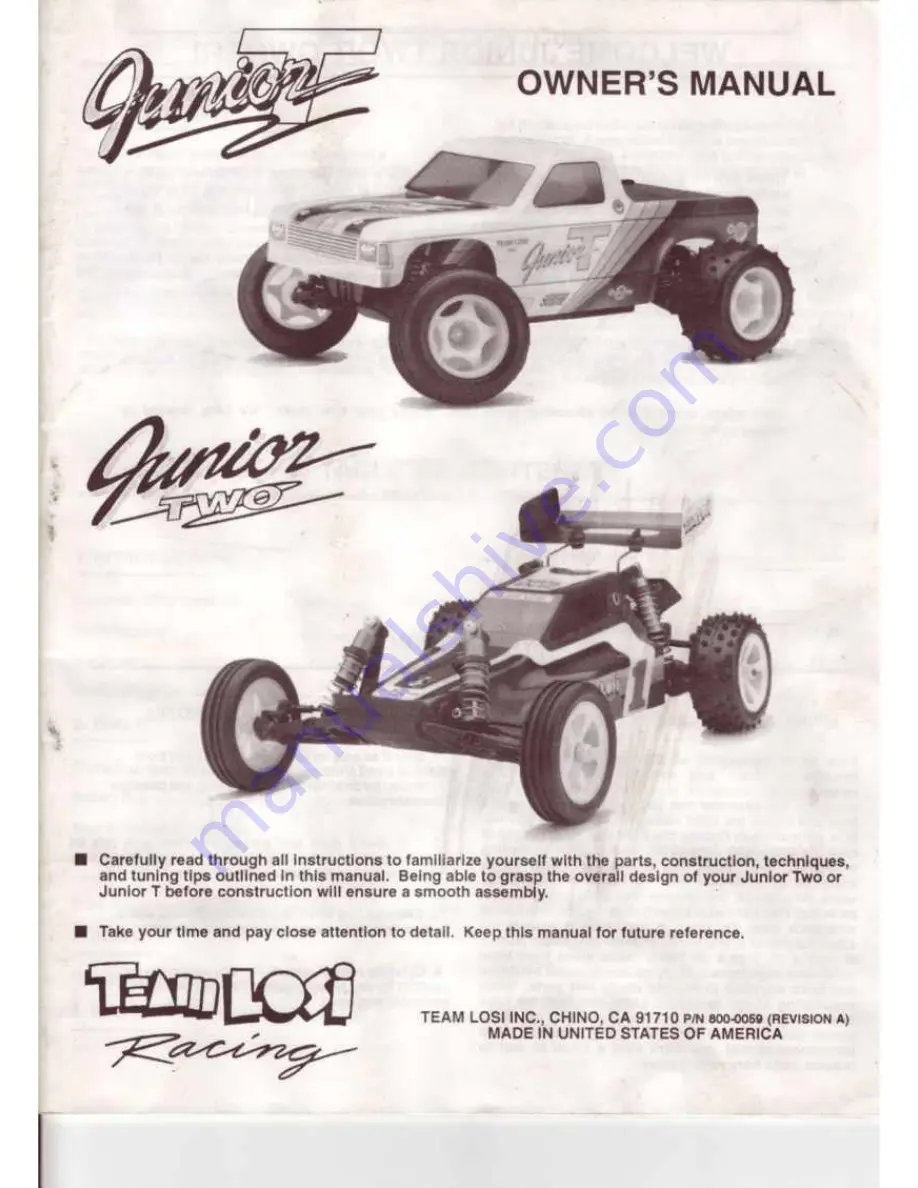
Page 1: ...uning tips outlined In this manual Being able to grasp the overall design of your Junior TWo or Junior T before construction will ensure a smooth assembly Take your lime and pay close attention to det...

Page 2: ...hat you opon onlyone bag at a time end follow the right sequence otherwise you will face difficulties In finding the right part It lji halpfi A to read the entire Instructions for the beg prior to sta...

Page 3: ...IDENTIFICATION When Inquestion uaetheherdwereldentlflc tlon guldaln Nch step Forecrewa the praflx number dtalgllltasthe crewala1nd numbatttnldtper Inch e g 4 40Isa Al4 lcrewwith 40thre de perInch The...

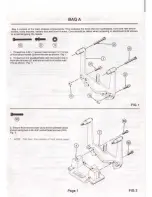
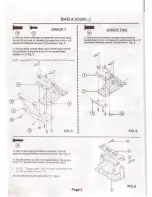
Page 4: ...avoid stripping the heads 0 1 Thrlld two4 40x t aocket head acrewa 121 to top ottront ahock tower 2 from Ihe rearn thown Fig 1 2 Thread two318 studded balla 22 into lower hole in front thocktower 2 e...

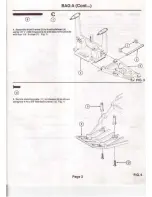
Page 5: ...mbltfront A anns 5 to front bulkhttd I using 1 r x 1 650hlngt pint 6 end securethepint 6 with lour 1 8 E cllps 7 Fig 3 5 Secure ttttrlng potts 1t tochisalt II 11 ahown ualngtwo4 40x3 8 lletheedacrewa...

Page 6: ...top m slit le I FIG S I I I I I I I I I I I I I I I I I I I I I I _ 8 Peel oil bacl ong lrom batttry box loam 13 and apply tottcess In bollomolbanery box lid 14 Fig 6 9 Secure battery boxlod 14 to ba...

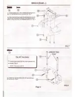
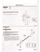
Page 7: ...Fig 7 12 Alllxantenna mount cap 18 onto antenna mount 19 and secure antenna mount 19 tochassis 9 as shown using one4 40 1 3 8 flathead screw 12 Fig 7 0 For JR Two Onlyl 12 Insert wing tubes 20 Into re...

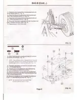
Page 8: ...sing four 4 40x 51 socket head screws J r _ 103 Fig 9 II s D 0 ts Attach rearbulkhead 21 tochaasil II auhown ualng two 8 32x 11 2 flithead elumlnumecrtws 10 in the rearend two 4 40 x3 8 fi Chead screw...

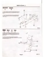
Page 9: ...a 118 atuddtd ball 3 and thraad Into an and hole ol the steering sector arm 27 Repeat lor opposite end 1 Sacuraateertng sectorarm 27 toidlerarm 28 and actn oaavtt 2S anhownua ng4 40x t 8 socket head s...

Page 10: ...rods 10 ThrNd enadjusteble rod end 34 ontobothsldes ola1718 thteadedrod 36 Thlaln11embly8 Fig 14 Then are front lie rods NOTE Use set up tool IOVided to cljust the lengths ol adJUSta e lmlt s To use...

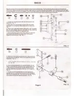
Page 11: ...ssls 9 asshown Fig 16 NOT Be sure setvQ arm 15 parul el and In line wr 11 rne scnbe mari s on rne chassts 9 as sl1own and a stUdded Qll 1 22 Is m steermg servo arm Fig 16 17 Thread an adjustable rod e...

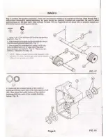
Page 12: ...ox shah 41 Fig 17 2 Sfldetnternel pmiongeer 42 downshah 41 sopm lnterlockawith groove m gear 42 Fig 17 3 Securegoor 42 onto ahah 41 using 3 16 E cllp 43 endattachtwo3 1e E cltps 43 fn theoth r grooves...

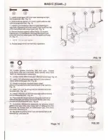
Page 13: ...om teeth on transmlulon aasembly 11 Locate centerdifferentialgear SO from small bag Fig 20 12 lnser13 32 differentialgearballs 51 Into holesIn centerdifferentialgear 50 Fig 20 13 Using a tooth pick ca...

Page 14: ...Fig 21 NOTE The wust washer sh0uk1 only rouchthe b1Q ocJQe olthe last oellow o 58 Gte tse thtusr oeeong side of washer only 11smd catoo byatrows 22 Shdtwellgreased bronze beenng cage O down 1CttW 57...

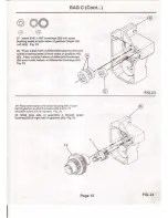
Page 15: ...aeals of both aides of gearbox 45 63 Place outside halves of differential bushings 64 over Inside halves of differential bushings 64 Fig 23 29 Placedifferentialonto center bearing 64 in nghl halfofgea...

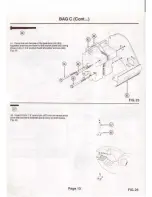
Page 16: ...45 63 together and aocurethemtothe motorplate 6 1 ualng three 4 40 x t 31 8 aocket head shoulderscrewa 66 Fig 25 32 Insert 3 32x 1 2 aporot pin 67 Intouniverul pivot Joont 68 sothalliextendaout evenly...

Page 17: ...emaledrive shaft 89 Fig 27A 35 Using remaining pinsin universal pivot Joint 68 repeat steps 33a nd 34 to securethe same universal plvolfoint 68 toU Jolnt ouldrive 48 Fig 27 B _ I 36 Repeatsteps 32 35...

Page 18: ...72 to chn sis 9 usong lour8 32x 1 2 steel flathead screws 39 Fig 29 41 Securegearbox torear bulkhead 21 UStr Q a 4 40 13 4 socket head screw 73 wttha 4 washer 74J underthe head Fig 29 42 Altach motorp...

Page 19: ...g 30 NOTE Hubs ara nondlrectlona assign a hub to one side and build 11 to su1t thatside 2 Prentwo 3 16 3 8 bushongs t80JoniO bOih socJes ol hub camert79 fog 30 3 Place hubcarm l 171l tn belween outerr...

Page 20: ...1 Fig 32 9 Secure H arm 81 82 with two 1 8 E clips 7 In grooves In 1 8 x 1 785hingepin 85 Fig 32 NOTE It s easiest If one groove In pin 85 Is given excess room to put on 118 clip 7 then pusn it Into t...

Page 21: ...88 Fig 34 12 Using pllere puahe 3132x 1 Z splrol pin 87 throughrearaxle 86 U Jolnlyokeandthrough univer sal pivotjOint 88 unUt pin 67 eXIendt evenlyoutof both aides ofrNraxle 86 F lg 34 13 Pry unlvar...

Page 22: ...themale drive shall 87 Intothe lemaladrlve ahall 69 F lg 36 B 17 Snap one adjusiJiblerod end 34 ofassembly F ontostudded ba I 22 Inrearbulkhead 21 and other end ontostudded ball 22 In hub carrier 79...

Page 23: ...e canrldgo body 124 snap the cartridge cap 127 onto the cartridge body 125 2 Make lour cnrtrldge uaemblles 1 Place a drop ot oil ongrooved end olshock st ah Front 88 Rear 89 1 end slide cartridge 90 h...

Page 24: ...o the bottom of the threads Fig 4t 9 ln ertshaft auombly with cartridge 90 against tho shock mount 97 Slowly tighten the cartridge allowing oil to bleed out u you do so until finger tight Secure by tu...

Page 25: ...thespnng Front 99 Rear 100 1 down over theshock to rest on he shock cup es Fig 42 14 lnsert4 40x3 8 socketheadscrew 101 mtothe largerclamp holt of lhtshock coll1r 102 and thread Into small hole Fig 43...

Page 26: ...24 Fig 44 6 19 Securetop of ahock with 1 40 nylon nut 76 Flg 44 6 II 0 20 For thefrontshocks align 1 4 shock mourn ball 96 in lower shock mount 117 with InsideholeIn front A Arm 6 Fig 46 A 21 Thread...

Page 27: ...ont wheel 107 Fig 46 JUNIOR T JUNIOR TWO I FIG 46 4 Repeat Step 2 on roar lire 106 and rear wheals 108 Flg 47 5 Tires and wheels are now ready for lnstollollon on axles Front 29 Rear 86 Install rear w...

Page 28: ...uclions lor gear cover on Page26 4 Removeantenna mount oap 18 fromantenna mount 19 on chassis 9 s Thread antenna wirethroughtube 114 so lhat3f4 ofthewire extends outtidethetube 1 14 Fig 49 6 Withwire...

Page 29: ...color alter a tight color apply a c oat of white over the tighter c olor tlrst Trim the shaded ponlon of the gNr cover body end wing along the cut linea marked on them Using the dimples In the body a...

Page 30: ...bottom wing button 131 so thot the flat wire holding edges are pointing Inward toward each other Tho mole top wing button 130 Is turned so that the Iorge notch Is also pointing Inward as shown In Fig...

Page 31: ...Toe In Toe Out Camber DISTANCE A LESS THAN B TOE II DISTANCE 8 LESS THAN A TOE OUl 0 r DIM 8 f DIM A TOP VIEW I CAMBER POSITIVE I NEGATIVE FRONTVIEW Page 28...

Page 32: ...moother dlff0rontlal Team Los offers Hard Balls part MTL 4016 TL 4017 These balls are made of a much harder material and offer a much longer tile than tho standard balls They will also improve tho per...

Page 33: ...all ruts 4 Lighter rurdampenlng will make Ihe car truck have more rearlraclion on low traclion surlaccs On high lracllon surfaces Ihe relit auspensron may rock from aide to aide exceulvoly with a ro8r...

Page 34: ...008 Shock Mount Bushong 4 24 Rear Shock Tower A 4048 Front Rear ShOCk Towers 25 Servo Saver A 1501 Servo Saver ld er Arm 1 26 Idler Arm A 1501 Servo Saver Idler Arm 1 27 Steering Sector Arm A 1510 Ext...

Page 35: ...A 3018 A 3018 A 6919 A 3001 A 6919 A 3002 A 6203 A BAOO A 3014 A 3013 A 3016 A 3988 TL3854 A 2018 A 6202 A 6215 A 6301 A 6212 A 3003 A 6213 A 2038 A 6919 A 2015 A 2015 A 4049 A 2022 A 4049 A 3015 A 3...

Page 36: ...0 114 Antenna Tube A 4002 Antenna K1t 115 Antenna Tips A 4003 Antenna Tips 8 118 4 40 X 1 8 Caphead Screw A 8200 4 40 X 1 8 Ca llead Screw 4 117 Oolferentoal AdJUStment Oust Cover A 3008 Oofferen al A...

Reviews: