background image

Installation Guide

7800 Series Gateway

November 3, 2017

Summary of Contents for 7800 N+1

Page 1: ...Installation Guide 7800 Series Gateway November 3 2017...

Page 2: ...ridges is committed to continually improving product designs as a result product specifications may be subject to change without notification 2003 2017 TelcoBridges All rights reserved TelcoBridges Tm...

Page 3: ...plies to a TMGIP7800 CTRL TMGIP7800 Telecom Unit and TMGIP7800 TMS 7800 TE This term is used when a description applies to the TMG7800 TE 7800 DS3 This term is used when a description applies to the T...

Page 4: ...TMG7800 Series System Installation Guide iv Contact Us If you have comments about this guide or any other TelcoBridges technical documentation please send an email to marketing telcobridges com...

Page 5: ...s Gateway Equipment 14 2 2 1 Prerequisites 14 2 2 2 Vertical Placement of the Equipment 14 2 2 3 Installing the 7800 Series Gateway on an Equipment Rack 15 2 2 3 1 7800 CTRL 15 2 2 3 2 7800 Telecom Un...

Page 6: ...o AC Power 41 4 6 2 Connecting to DC Power 42 Section 5 Installing the 7800 TMS 45 5 1 Connecting to the Control Network 45 5 2 Grounding the Equipment Chassis 46 5 2 1 7800 TMS 46 5 3 Powering Up 47...

Page 7: ...Series Gateway Management Port IP Address 62 9 4 Retrieving 7800 Series Gateway Information 63 9 5 Changing 7800 Series Gateway Management Port Passwords 63 9 6 Configuring the 7800 Series Gateway Usi...

Page 8: ...TMG7800 Series System Installation Guide viii...

Page 9: ...he installation and setup of a 7800 Series Gateway The following topics are covered Section 1 1 Identifying the 7800 Series Gateway Equipment Section 1 2 Installation Prerequisites Section 1 3 Prevent...

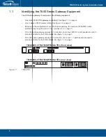
Page 10: ...7800 series gateway the number of 7800 TMS media switche s may range from zero to two See figure 1 3 on page 3 If the 7800 series gateway employs N 1 protection one to two 7800 N 1 patch panels are us...

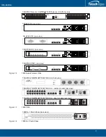
Page 11: ...OIP 0 1 0 1 TMS 0 1 MGMT0 ETH VOIP 0 1 0 1 TMS 0 1 MGMT0 ETH VOIP 0 1 0 1 TMS 0 1 BITS0 BITS1 0 2 4 6 8 10 12 14 1 3 5 7 9 11 13 15 0 2 4 6 8 10 12 14 1010 ETH0 ETH1 TMG7800 TMS TMGIP7800 TMS Unit fro...

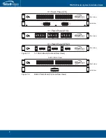
Page 12: ...Views 1 1 Patch Panel TE 1 1 Patch Panel DS3 1 1 Patch Panel STM1 Gateway Gateway Gateway Gateway APS Main APS Main APS Main front view rear view front view front view Gateway Gateway 1 1 Network Gate...

Page 13: ...for the installation of the 7800 CTRL You must mount the 7800 CTRL on a 19 equipment rack customer provided Your 7800 CTRL is a 1U unit Plan for an additional 1U space on the equipment rack for a redu...

Page 14: ...00 Series Telecom Units Adequate space for the installation of each 7800 Series Telecom Unit You will need to mount each 7800 Series Telecom Unit 1 16 units on a 19 equipment rack customer provided Ea...

Page 15: ...Panel If your system employs 1 1 protection you will need to mount one or two 7800 1 1 patch panels on a 19 equipment rack customer provided Your 7800 1 1 patch panel is a 1U unit Adequate power suppl...

Page 16: ...ocks the wrist strap and cord must be in proper working condition If no wrist strap is available and you must work with Tmedia VoIP Gateways ground yourself by touching a metal part of the chassis 1 4...

Page 17: ...llation Preparations Section 2 Installation Preparations This section provides information about the following topics Section 2 1 Package Contents Section 2 2 Rack Mounting the 7800 Series Gateway Equ...

Page 18: ...ion 2 1 4 7800 N 1 Patch Panel on page 12 The contents of these devices are described in the following sections 2 1 1 7800 CTRL Gateway Controllers In the box you will find the following items One Del...

Page 19: ...hernet blue straight cables male male 3 meters in length One Important Notice two sided document containing pertinent product serial numbers and other important information One Product Warranty One pa...

Page 20: ...rack The 7800 TMS must be installed on a 19 wide equipment rack You must order one TelcoBridges CAT7 shielded Ethernet crossover cable with RJ45 type male male connectors for each connection between 7...

Page 21: ...respective 1 units and the network you will required one 1 1 Patch Panel 32 T1 E1 To connect the 7800 TE 48 and the 7800 TE 64 to their respective 1 units and the network you will require two 1 1 Pat...

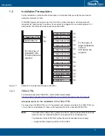
Page 22: ...s tabulated in table 2 2 on page 14 It is important that you provide for enough room on the equipment rack to allow for the installation of the equipment Consider the available space on your equipment...

Page 23: ...e 14 3 Repeat steps 1 and 2 for each additional 7800 Telecom Unit Note If you are installing TMG7800 TE units you will require one to two patch panels per TMG7800 TE Mount the patch panels beneath eac...

Page 24: ...as described in Section 2 2 2 Vertical Placement of the Equipment on page 14 3 If required repeat steps 1 and 2 for a second 7800 1 1 patch panel 2 2 3 6 7800 RJ48C Patch Panel Mounting the 7800 RJ48...

Page 25: ...n covers the following procedures Section 3 1 Connecting to the 7800 Series Gateway Management Interface on page 18 Section 3 2 Connecting to the 7800 Series Control Network on page 19 Section 3 3 Con...

Page 26: ...the following is needed Two CAT5 Ethernet cables with RJ45 male male terminations Note Ethernet cables are not supplied with the 7800 CTRL To communicate with the Management Interface 1 Connect an RJ4...

Page 27: ...o CAT5 Ethernet cables with RJ45 male male terminations Connections The 7800 CTRL is connected to the control network using two CAT5 Ethernet cables as shown in figure 3 2 on page 19 To connect to the...

Page 28: ...are configured using the Web Portal Prerequisites To connect the 7800 CTRL to the data network using a 1Gb connection you will need Gigabit layer 2 Ethernet switch A second one is required to support...

Page 29: ...power the 7800 CTRL you will need Two independent AC power sources Two power cables 3 4 1 Connecting to AC Power The 7800 CTRL is furnished with two AC power supplies To connect the 7800 CTRL to AC P...

Page 30: ...TMG7800 Series System Installation Guide 22...

Page 31: ...llowing procedures Section 4 1 Connecting to the Control Network on page 24 Section 4 2 Connecting to the VoIP Network s on page 25 Section 4 3 Connecting to the PSTN on page 26 Section 4 4 Connecting...

Page 32: ...unit Connections The 7800 Telecom unit s are connected to the control network using two CAT5 Ethernet cables as shown in figure 4 1 on page 24 To connect to the control network 1 Connect the ETH0 con...

Page 33: ...oIP network you will need Two gigabit layer 2 Ethernet switches A second one is required to support redundancy of the VoIP interface Two CAT5 Ethernet cables with RJ45 male male terminations Two IP ad...

Page 34: ...Standalone Configuration You will require two coaxial cables for each DS3 interface 1 1 Configuration Your 7800 DS3 and 7800 DS3 1 feature BNC connectors for connection to DS3 lines using a 1 1 patch...

Page 35: ...to convert to 75 ohms Note All ports may not be active T1 E1 ports are activated by software license the number of active ports depends on the licenses purchased Patch panels use straight connections...

Page 36: ...RJ48C patch panel number 1 ports 0 15 Connect SCSI ports 16 31 to patch panel number 1 ports 16 31 2 Repeat step 1 using lines 32 63 and a second RJ48C patch panel Connect lines 32 47 to patch panel 2...

Page 37: ...of the 7800 TE 3 Connect SCSI ports 16 31 from the Gateway section at the rear of the 1 1 patch panel to the SCSI ports 16 31 of the 7800 TE 4 Connect SCSI ports 0 15 from the Gateway 1 1 section at t...

Page 38: ...TMG7800 Series System Installation Guide 30 Figure 4 4 7800 TE and 7800 TE 1 connecting to the TDM 1 1 32 T1 E1 1 1 patch panel From Network 3200 TE 3200 TE 1 rear view front view...

Page 39: ...censes purchased 4 3 2 1 Standalone Configuration To connect the TMG7800 DS3 to the PSTN 1 Start with the Dual BNC port pair 0 right most as shown in figure 4 5 on page 31 Connect one pair of BNC cabl...

Page 40: ...3 Connect each DS3 line from the DS3 connectors labeled 1 1 of the 1 1 patch panel to the 7800 DS3 1 Optional 1 Connect bits port 0 and 1 from the 7800 DS3 to the 1 1 patch panel 2 Connect bits port...

Page 41: ...ferent model from the one that has been provided you must replace it Table 4 1 STM 1 Interfaces A TMG7800 STM1 with one main and one backup APS OC3 or STM1 port enables connection to OC3 STM1 lines Se...

Page 42: ...nel to the remote equipment See figure 4 8 on page 35 2 Connect a fiber optic cable between STM1 of the Gateway section of the 1 1 patch panel and the main port of the 7800 STM1 3 Connect a fiber opti...

Page 43: ...r optic cables from the network provider with each TMG7800 STM1 and use the same port number that is assigned to each TMG7800 STM1 See figure 4 9 on page 36 3 If Automatic Protection Switching APS is...

Page 44: ...ee Installing the 7800 N 1 Patch Panel on page 49 for more information Network Gateway 1 3 5 7 9 11 13 0 2 4 6 8 10 12 14 N 1 Network Gateway 1 3 5 7 9 11 13 0 2 4 6 8 10 12 14 N 1 7800 N 1 Gateway Ma...

Page 45: ...lcoBridges CAT7 shielded Ethernet cable with RJ45 male male terminations for each 7800 Telecom Unit 4 4 1 2 Interconnections To interconnect the 7800 TMS 1 Start with the 7800 Telecom Unit at the topm...

Page 46: ...to an active and standby 7800 TMS TMG7800 TMS TMG7800 Telecom Unit TMG7800 Telecom Unit TMG7800 TMS BITS0 BITS1 1 3 5 7 9 11 13 15 0 2 4 6 8 10 12 14 ETH0 ETH1 IOIOI BITS0 BITS1 1 3 5 7 9 11 13 15 0...

Page 47: ...ridges CAT7 shielded Ethernet crossover cables with RJ45 type male male connectors Simply connect the TMS0 ports of each unit together using a TelcoBridges CAT7 shielded cross over cable with RJ45 mal...

Page 48: ...terminal Keep the length of the ground wire as short as possible Do NOT daisy chain the ground between equipment Use a ground bus bar as show in figure 4 12 on page 40 Do not over tighten ground lug...

Page 49: ...ing to AC Power Prerequisites To power the 7800 Telecom Unit you will need One to two power sources Two power cables The 7800 Telecom Unit AC model is furnished with two AC power connectors To connect...

Page 50: ...pply must be protected with a customer provided 5A 48V fuse To connect o DC power 1 Connect one wire from the positive terminal of the 7800 series gateway to the return side of DC power source one as...

Page 51: ...ries Telecom Units Figure 4 14 DC Power Connection MGMT0 ETH VOIP 0 1 0 1 TMS 0 1 DC Power Source 1 Return 48V Earth Ground Power Supply Mounting Screws Do not unscrew Earth Ground 5A fuse Return 48V...

Page 52: ...TMG7800 Series System Installation Guide 44...

Page 53: ...t the 7800 TMS you will need Two CAT5 Ethernet cables with RJ45 male male terminations Connections The 7800 TMS is connected to the 7800 series control network using two CAT5 Ethernet cables as shown...

Page 54: ...stranded ground wire Terminate equipment side of ground wire with a 10 ring terminal Keep the length of the ground wire as short as possible Do NOT daisy chain the ground between equipment Use a groun...

Page 55: ...ne to two power sources Two power cables 5 3 1 Connecting to AC Power The 7800 Telecom Unit AC model is furnished with two AC power connectors To connect the 7800 Telecom Unit to AC Power 1 Connect an...

Page 56: ...ground wire from the ground terminal of the 7800 TMS to earth ground 4 Repeat steps 1 3 for the second power DC power source Figure 5 4 7800 TMS DC wiring diagram 5 4 TDM System Clock The 7800 series...

Page 57: ...This section covers the following procedures Section 6 1 Connecting Fiber Optic Cables to the 7800 N 1 Patch Panel on page 50 Section 6 2 Connecting to the Control Network on page 50 Section 6 3 Grou...

Page 58: ...eed Two CAT5 Ethernet cables with RJ45 male male terminations for each 7800 N 1 patch panel Connections The 7800 N 1 patch panel s are connected to the control network using two CAT5 Ethernet cables a...

Page 59: ...of ground wire with a 10 ring terminal Keep the length of the ground wire as short as possible Do NOT daisy chain the ground between equipment Use a ground bus bar Do not over tighten ground lug conn...

Page 60: ...wered up Prerequisites To power the 7800 N 1 patch panel you will need One to two power sources Two power cables To connect the 7800 N 1 Patch Panel to AC Power 1 Connect an AC power cable between the...

Page 61: ...o the web portal of the 7800 CTRL primary unit 2 Follow the web portal instructions to configure your unit as a primary unit in a new 7800 series system 3 Before clicking the yes it is connected like...

Page 62: ...to Dell s documentation http www dell com support home us en 04 product support product poweredge r330 manuals 7 2 2 7800 Telecom Unit Front of unit When the equipment is powered verify the front pan...

Page 63: ...ble 7 2 on page 55 Table 7 2 7800 TMS Displays When pressing the reset button the following will appear it is only possible to restart no shutdown option available Reset Yes No Select with the functio...

Page 64: ...gured but no laser is received GW Black Configured normal state or not configured Blinking yellow Unit replaced by backup unit Blinking red Replaced but no signal is received from the network N 1 Blac...

Page 65: ...nute Be aware that the shutdown procedure of the unit is logged and traceable for support and warranty purposes 8 1 1 Local Method To power down the 7800 CTRL refer to the Dell documentation http www...

Page 66: ...he unit The unit can be restarted using restart button on the front of the unit Note As an alternate method to this procedure refer to Section 7 2 2 7800 Telecom Unit on page 54 to power down the Tmed...

Page 67: ...way SSH Connection Section 9 2 7800 Series Gateway Serial Connection Section 9 3 Changing the 7800 Series Gateway Management Port IP Address Section 9 4 Retrieving 7800 Series Gateway Information Sect...

Page 68: ...2 1 Connecting to the 7800 CTRL Console Note The default IP addresses for the management ports are located in the Important Notice sheet received with the shipment MGMT ports are configured in bonding...

Page 69: ...e cable to a USB port on your computer and the DB9 male connector of the cable to one end of a null modem DB9 female female cable Connect the other end of the null modem DB9 female female cable to the...

Page 70: ...n to communicate with the 7800 series system in order to configure initial settings Available terminal emulation software includes SecureCRT Putty Minicom To configure the terminal emulator applicatio...

Page 71: ...al number See http docs telcobridges com mediawiki index php TMG Get_Serial_Number for further information 9 5 Changing 7800 Series Gateway Management Port Passwords Once logged you are logged on to t...

Page 72: ...eb browser The default url is http 7800 ctrl MGMT0 IP address 12358 Note If your system features two 7800 CTRL units they can access the Web Portal from either one of their IP addresses The default lo...

Page 73: ...s This section provides information about the following topics Section 10 1 Creating a Database Backup Section 10 2 Downloading a Database Backup Section 10 3 Uploading a Database Backup Section 10 4...

Page 74: ...system has been configured Backups are performed using the web portal 10 2 Downloading a Database Backup A backup of system data is stored on the hard drive of the 7800 series gateway It is important...

Page 75: ...67 Appendix A Wiring Diagrams...

Page 76: ...48 T1 E1 J1 Wiring Schematic Crossover Cable 1 8 RX Ring 1 RX Tip 2 Not Connected 3 TX Ring 4 TX Tip 5 Not Connected 6 Not Connected 7 Not Connected 8 1 RX Ring 2 RX Tip 3 Not Connected 4 TX Ring 5 T...

Page 77: ...69 Wiring Diagrams A 2 RJ48 Console Wiring Diagram 1 N C 2 Rx 3 Tx 4 N C 5 GND 6 N C 7 N C 8 N C 9 N C 1 N C 2 N C 3 N C 4 GND 5 Tx 6 Rx 7 N C 8 N C DB 9 RJ 45 2 3 5 1 8...

Reviews: